- You are here:
-
Home

-
Contents (2)
-
Part XVII. Services and Trade
-
Transport Industry and Warehousing
-
Storage
- Frederick, James S.

Wegmüller, Beat
Address: Suva-Caidde Nationale Suisse d'Assurance, Postfach 4358, CH-002 Lucerne
Country: Switzerland
Phone: 41 41 419-5373
Fax: 41 41 419-5757
Areas of interest: Safety and health in the woodworking industry
Wood Planning Machines
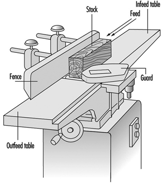
The development of stationary planing machines can be traced back to the beginning of the 19th century. On the first machines of this type, the workpiece was clamped to a carriage and fed below a horizontal shaft fitted with blades extending over the full working width. In 1850 a planing machine was built in Germany on which the workpiece was fed over a cutterblock located between two tables used to position and to support the workpiece. Apart from technical improvements this basic design has been maintained to this day. Such a machine is called a surface planing machine or a jointer (see figure 1).
Figure 1. Jointer
More recently, machines were designed to plane the upper surface of a workpiece to a predetermined thickness by means of a horizontally rotating cutterblock. The distance between the cutting circle diameter and the surface of the table supporting the workpiece is adjustable. Such machines are called one-side-thickness planing machines.
These two basic machine types were eventually combined into a machine which could be used for both surface and thickness planing. This development ended in planing machines for two-, three- and four-sided working in one pass.
From the point of view of occupational safety and health, it is strongly recommended that measures be taken for the extraction of wood dust and chips from the planing machine (e.g., by connecting the planing machine to a dust extraction system). Dust originating from hardwood (oak, beech) and tropical wood is considered a particular health hazard and must be extracted. Measures to reduce the noise level of planing machines should also be taken. An automatic brake for the cutterblock is compulsory in many countries.
Surface Planing Machines
A surface planing machine has rigid main frame that supports the infeed and the outfeed table. The cutterblock is located between the two tables and mounted on ball bearings. The main frame should be ergonomically designed (i.e., it should enable the operator to work comfortably).
Hand-operated control devices should be installed in such a way that the operator is not placed in a hazardous situation when operating them, and the possibility of inadvertent operation should be minimized.
The side of the main frame facing the operator’s position must be free of projecting parts such as handwheels, levers and so on. The table to the left of the cutterblock (outfeed table) is normally set at the same height as the cutting circle of the cutterblock. The table to the right of the cutterblock (infeed table) is set lower than the outfeed table to obtain the desired depth of cut. Contact between the table lips and the cutterblock should not be possible over the full setting range of the tables. However, the clearance between the table lips and the cutting circle of the cutterblock shall be as small as possible to provide for good support of the workpiece to be planed.
The major operations on a surface planing machine are flatting and edging. The position of the hands on the workpiece is important from an operational and safety viewpoint. When flatting, the workpiece should be fed with one hand, with the other hand holding it down initially on the infeed table. As soon as there is a sufficient portion of timber on the outfeed table, the latter hand can pass safely over the bridge-guard to apply pressure on the outfeed table and will be followed by the feeding hand to complete the feeding operation. When edging, the hands should not pass over the cutterblock while in contact with the timber. Their prime function is to exert horizontal pressure on the workpiece to maintain it square to the fence.
The noise produced by the rotating cutterblock often may exceed the level considered harmful to the ear. Measures to reduce the noise level are therefore necessary. Some of the noise reduction measures which have proved successful on surface planers are the following:
- use of a “quiet” cutterblock (e.g., a round form with minimum blade projection, helical blade instead of straight blade, segmental rotating tools with offset cutting)
- slotted or drilled table lips (the configuration and the dimensions of the apertures in the table lips must be selected so that no accident hazards arise; e.g., slots shall be no more than 6 mm wide and the diameter of the holes shall not exceed 6 mm)
- aerodynamic design of the chip deflectors below the table lips
- reduction of the cutterblock speed to below 1,000 rpm, provided the surface quality of the workpiece is still satisfactory.
Noise reduction up to 12 dBA when idling and 10 dBA under load can be achieved.
Cutterblocks should have a circular cross-section, and the chip clearance grooves and slots should be as small as possible. The blades and inserts shall be properly secured, preferably by form lock fixing.
The cutterblock rotates generally at speeds between 4,500 and 6,000 rpm. The diameters of conventional cutterblocks vary from 56 to 160 mm, and their lengths (working widths) from 200 to 900 mm. By analogy with the kinematics of conventional milling, the surface of the workpiece planed with a cutterblock is composed of cycloid arcs. The surface quality of the work therefore depends on the speed and diameter of the cutterblock, the number of cutting blades and the feed rate of the workpiece.
Equipping surface planing machines with an automatic brake for the cutterblock is recommended. The brake should be activated when the machine is stopped, and the braking time should not exceed 10 seconds.
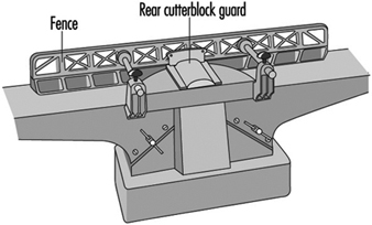
Access to the cutterblock at the rear of the fence should be prevented by a guard attached either to the fence or the fence support. The cutterblock in front of the fence should be guarded by an adjustable bridge-type guard fixed to the machine (e.g., to the main frame on the outfeed table side) (see figure 2). Access to the transmission elements should be prevented by a fixed guard.
Figure 2. Fence & rear cutterblock guard
Hazards
As the cutterblock rotates opposite to the direction in which the workpiece is fed, the hazard of kickback exists. If the workpiece is ejected, the operator’s hand or fingers may come in contact with the rotating cutterblock unless adequate guarding has been provided. It also frequently happens that the hand comes in contact with the cutterblock while feeding the workpiece with stretched fingers instead of pushing it forward with closed fist. Cutting blades not properly secured may be ejected by centrifugal force and may cause severe injury and/or material damage.
Guarding systems for surface planing machines
In many countries legislation covering the use of surface planing machines requires that the cutterblock be covered by an adjustable guarding system in order to prevent accidental contact of the operator’s hand with the rotating cutterblock.
In 1938, the SUVA introduced a planer guard which efficiently met all practical requirements. Over the years this guard has proved useful not only as a guarding system but also as an aid for most operations. It is well accepted by the woodworking trade in Switzerland, and almost all industrial surface planing machines are equipped with it. The design features of this guard have been introduced into the draft European standard for surface planing machines. The main features of this guard are the following:
- strong and rigid
- not easily deflected to expose cutterblock
- always stays parallel to the cutterblock axis regardless of its horizontal or vertical adjustment
- easily adjustable horizontally and vertically without the use of a tool.
However, accidents still happen. These accidents are mainly caused by failure to adjust the guard properly. Therefore, SUVA engineers have developed a bridge-type guard which covers the cutterblock in front of the fence automatically, and constantly exerts a defined pressure against the workpiece or the fence. This guard has been available since 1992.
The main design features of this new guard, called “Suvamatic”, are the following:
- complete guarding of the cutterblock. The full planing width is safeguarded by one single bridge-type guard. It can be folded down using a hinged locking system. This prevents the guard from projecting too far over the face of the machine.
- practical workpiece guiding system. The workpiece guiding system consists of a pressure pad and a guide for the workpiece. Both are fitted to the tip of the guard. The latter can be tilted to guide the workpiece both for flatting and edging.
- pressure application to assist work. For edging, the guard exerts pressure in direction of the fence. After edging, it automatically covers the full length of the cutterblock in front of the fence.
- automatic lifting and lowering of the guard. For flatting, the guard is lifted by the workpiece guide. After flatting, it lowers itself automatically to cover the cutterblock.
- guard can be locked in position for batch jobs. For batch jobs, the guard can be locked in vertical position to just accommodate the thickness of the workpiece. The guard will return automatically to this preset position after being pressed down.
- will fit all machines. The guard can be fitted to all surface planing machines and combined surface and thickness planing machines.
One-Side Thickness Planing Machines
The main frame of a one-side thickness planing machine houses the cutterblock, thickness planing table and feed elements.
Once the workpiece has been flattened and edged on a surface planing machine, it is planed to the desired thickness on the thickness planing machine. Unlike that of a surface planing machine, the cutterblock of a thickness planing machine is located above the planing table and the workpiece is no longer fed by hand but mechanically by feed rollers. The feed rollers are driven either by a separate motor (approximately 1 kW) or via a speed-reduction gearbox receiving its power from the cutterblock motor. With a separate drive the feed rate remains constant, but if the power is transmitted from the cutterblock motor the feed rate varies according to the cutterblock speed. Feed rates between 4 and 35 m/min are common.
Two spring-mounted feed rollers rest on the upper surface of the workpiece. The feed roller in front of the cutterblock is grooved for better grip on the workpiece; the feed roller at the outfeed end of the cutterblock is smooth. An infeed and an outfeed pressure bar located next to the cutterblock press the workpiece down onto the table, thereby ensuring a clean and even cut. The design and arrangement of the feed rollers and pressure bars should be such that contact with the rotating cutterblock is impossible.
Sectional feed rollers and pressure bars allow for the simultaneous working of two or more workpieces of slightly different thickness. From the point of view of accident prevention, sectional feed rollers and pressure bars are essential. The width of the individual feed roller or pressure bar section should not exceed 50 mm.
Two idle rollers are arranged in the table. They are designed to facilitate the passage of the workpiece over the table.
The surface of the table must be a plane free from slots or holes. Accidents involving an operator’s fingers being squeezed between openings and the workpiece have occurred. Vertical adjustment of the table may be manual or power assisted. A mechanical end-stop should prevent any contact of the table with the cutterblock or feed rollers. It must be ensured that the vertical adjustment mechanism hold the table in a stable position.
In order to prevent the feeding of oversize workpieces, a device (e.g., a fixed rod or fixed bar) is located on the infeed side of the machine, thereby limiting the maximum workpiece height. A maximum height of 250 mm between the surface of the table in its lowest position and the above-mentioned safety device is rarely exceeded. The usual working width varies between 315 and 800 mm (for special machines this width might go up to 1,300 mm).
The cutterblock diameter generally varies from 80 to 160 mm. Normally four blades are fitted to the cutterblock. The cutterblock rotates at speeds between 4,000 and 6,000 rpm, and its input power varies from 4 to 20 kW. The maximum depth of cut is 10 to 12 mm.
To minimize the danger of kickback, one-side thickness planing machines should be fitted with an anti-kickback device covering the full working width of the machine. This anti-kickback device generally consists of several grooved elements arranged on a rod. The individual element is between 8 and 15 mm wide, and it falls under its own weight to the rest position. The lowest point of the individual grooved element in its rest position should be 3 mm below the cutting circle of the cutterblock. The grooved elements should be made of a material (preferably steel) with a resilience strength of 15 J/cm2 and a surface hardness of 100 HB.
The following noise-reduction measures have proved to be successful on one-side thickness planing machines:
- use of a “quiet” cutterblock (like that suggested for surface planing machines)
- aerodynamic design of the pressure bars and the chip extraction hood
- reduction of the cutterblock speed
- partial or complete enclosure of the machine (tunnel-like design of the infeed and outfeed opening with sound-absorbing material on the surface facing the source of noise)
Noise reduction of up to 20 dBA may be achieved by a well designed complete enclosure.
Hazards
The major cause of accidents on one-side thickness planing machines is kickback of the workpiece. Kickback may happen because of:
- poor maintenance of the anti-kickback device (the individual elements may not fall free under their own weight but stick together because of dust accumulation; the grooves in the elements may be covered with resin, be blunt or be incorrectly reground)
- poor maintenance of the sectional feed rollers and pressure bars (e.g., resin-covered or rusty sections)
- insufficient spring load on feed rollers and pressure bars when several pieces of non-uniform thickness are fed at the same time.
Typical causes of other accidents are:
- contact of the hand with the rotating cutterblock when removing chips and dust from the table by hand rather than with a wooden stick or rake
- ejection of cutterblock blades due to incorrect fixing.
Combined Surface Planing and Thicknessing Machines
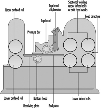
The design and operation of combined machines (see figure 3) are similar to those of the individual machines described above. The same can be said in regards to the feed rates, motor power, table and roller adjustments. For thickness planing the surface planing tables are either pulled away, folded down or lifted up sideways, exposing the cutterblock, which is covered by a chip extraction hood to prevent access Combined machines are mainly used in small workshops with few workers, or where space is limited (i.e., in cases where the installation of two individual machines is impossible or unprofitable).
Figure 3. Combined surface & thickness planer
The changeover from one operation to the other is often time-consuming and may be annoying if only a few pieces have to be machined. Moreover, usually only one person at a time can use the machine. However, since 1992 machines have been introduced to the market where simultaneous operation (surface and thickness planing at the same time) is possible.
The hazards of combined machines are to a large extent identical to the hazards listed for the individual machines.
Routing Machines
Stationary routing machines are used in general for the manufacture of wood articles and furniture elements, but sometimes also for machining plastics and light alloys. Important types of routing machines are copy routers, pattern millers, machines with mobile router heads and automatic copying machines. The automatic copying machines are generally used for machining several workpieces simultaneously.
A common feature of all routing machines is that the tool is located above the workpiece support, which is normally a table. The tool-spindle axis is nearly always vertical, but on some machines the router head, and thus also the tool-spindle axis, may be tilted. The machining head is lowered for machining and returns automatically to its initial (rest) position. On older machines the machining head is lowered manually by operating a mechanical foot-pedal or hand lever. On modern machines the head is generally lowered by a pneumatic or hydraulic system. Figure 1 shows various accessories (hold-down shoes, guides and so on) and the Swiss National Accident Insurance Organization (SUVA) safety guard.
Figure 1. SUVA safety device with routing tool in working position

The tool-spindle is driven either by a belt drive or directly by a high-frequency motor, which is often of the two-speed type. The tool-spindle speeds generally range from 6,000 to 24,000 rpm. They are lower in pattern millers, where the lowest speed may be 250 rpm. Pattern millers are often equipped with a gearbox for the selection of different speeds.
The cutting diameter of the routing tool varies from 3 to 50 mm. However, on special pattern millers the cutting diameter of the tool may be as large as 300 mm.
Tooling
On routing machines single-edged spoon bits, double-edged panel cutters or solid-shaped cutters mainly are used. Like any tool they must be designed and made of such materials that will withstand the forces and loads to be expected during operation. Machines should be used and maintained in compliance with the manufacturer’s instructions.
The routing tools should be:
- clearly and permanently marked with the permissible speed, e.g., less than 20,000 rpm
- of a type tested by an approved body
- of round form design with a minimal radial cutting edge projection to reduce the danger of kickback.
Guarding of the tool
On routing machines where the tool is moving and the workpiece remains fixed, access to the rotating tool should be prevented by an adjustable guard (hand protector). It should be supplemented by a movable guard which can be lowered on to the workpiece surface. The lower end of this movable guard may be a brush.
On routing machines where the workpiece is held and/or fed by hand, it is highly recommended to use a safety device exerting vertical pressure on the workpiece. The SUVA has designed such a guard. This safety device has been successfully used since the end of the 1940s and is still the most complete guard of its kind. Its main features are:
- prevention of unintentional contact with the rotating tool both in its rest position and in its working position
- fast and easy changeover from one size of hold-down shoe to another. Several sizes of hold-down shoes are available to fit tools with different cutting diameters
- manually adjustable amount of pressure exerted on the workpiece by the hold-down shoe
- automatic return of the hold-down shoe to its upper position when the router head rises to its rest position. The guarding device can be adjusted so that the hold-down shoe may be lifted only when the lower edge of the tool is above the level of the lower edge of the hold-down shoe; this is to prevent any unintentional contact with the tool from below (see figure 2. Serious injuries to the back of the hand, where the tendons are protected only by the skin, are thus avoided.
Figure 2. Safety device with routing tool in initial position
- possibility of connection of a chip extraction system to the guarding device.
This guarding device also enables workpieces to be routed along a guide with the aid of a horizontal pressure pad.
Hazards
Routing machines have been found to be less dangerous than vertical spindle moulding machines. One reason for this is the smaller diameter of most routing tools. However, the tools on routing machines are easily accessible and thus present a constant hazard for the hands and arms of the operator. Therefore, copy routers, where the workpiece is generally fed by hand, are by far the most dangerous routing machines.
Causes of accidents
The main causes of router accidents are:
- unintentional contact of the hand or arm with the rotating tool in its rest position (1) when removing chips and dust from the table by hand rather than using a wooden stick, (2) when the workpiece or the jig is not correctly handled or (3) when the sleeve of the operator’s clothing becomes entangled in the rotating tool
- unintentional contact of the hand with the routing tool as a result of kickback of the workpiece held by hand.
Kickback may happen because of:
- an unsafe working practice
- faults in the workpiece (knots, etc.)
- workpieces being fed into the tool too abruptly or from the wrong direction
- blunt cutter edges
- inadequate cutting speed
- incorrect fixing of the workpiece to the jig
- workpiece breakage
- ejection of the tool or parts of the tool due to bad tool design, excessive hardness of the tool material, faults in the material of the tool, overspeed of the tool or poor clamping of the tool in the tool holder.
In the event of ejection of a tool or workpiece, not only the operator but also other persons working in the area may be injured by ejected parts.
Measures to prevent accidents
Measures to prevent accidents should be directed at:
- the design and construction of the machine
- the tooling
- guarding the tool in its rest position (figure 15) and as far as possible in the working position (figure 14), in particular when the workpiece is held and fed by hand.
Design and Construction of the Machine
Routing machines must be designed to be safe to operate. It should be ensured that:
- the machine is sufficiently rigid
- the electrical equipment conforms to safety regulations
- actuators used to initiate a start function or movement of a machine element are constructed and mounted so as to minimize inadvertent operation
- access to moving machine parts, such as belt drives, hydraulic or pneumatically moved router heads or travelling tables on machines with automatic feeds, are prevented by adequate guarding
- the actual revolutions per minute of the tool are clearly visible to the operator
- the safety devices and chip extraction systems are easy to install
- the noise level of the machine is reduced as far as possible.
Furthermore, it is advisable to equip the tool drive of the routing machine with an automatic brake that activates when the machine is stopped. The braking time should not exceed 10 seconds.
Sample checklist
Housekeeping
1. A daily housekeeping programme is essential.
2. Dust accumulations of 1/8” depth in any area indicate a need for cleaning. It should be noted that any accumulation of dust may lead to a fire. The finer the dust, the greater the hazards.
3. Clean wood dust frequently.
a. Wipe down daily around hot surfaces.
b. Major blow down or vacuum when possible of all areas, including rafters, at least twice per year.
c. When concentrations are high, work small areas at a time.
d. Low humidity increases the potential for hazards and should be taken in consideration during blow downs.
4. Schedule blow downs or clean ups while equipment is down, such as Friday afternoons and weekends.
Electrical maintenance
1. Inspect/clean all motors regularly to avoid dust build-up.
2. Ensure all electrical boxes and panels meet the National Electrical Code requirements for their classified location.
3. Listen for unusual sounds, note unusual smells and watch for visual dust accumulations on machines and motors. Check motors and other electricals often to detect overheating.
4. Ensure that maintenance or operating personnel are lubricating bearings to motors, conveyors, chains and sprockets on a timely basis.
5. Ensure that electrical panels and boxes are kept closed and maintained to prevent dust accumulations, including keeping all knockout holes plugged.
Fire prevention
1. Actively prohibit smoking in unauthorized locations.
2. Adopt procedures for hot-work permits and ensure that procedures are followed.
3. Do not allow operator-controlled machines to operate unattended.
4. Install a device at the mouth of the dust collecting system to prevent sanding belts and other spark producing items from entering the system and causing a fire.
5. Trap metal in wood hogs by installing magnets in the conveyor system and metal detectors in the hog. Policies and procedures should be implemented to prevent metal and other foreign objects from reaching the hogs.
6. Conduct weekly and monthly inspections of fire protective systems including fire extinguishers, fire hoses, alarms and sprinkler control valves.
7. Ensure that boiler rooms and heating equipment are free of dust accumulations, that written boiler start-up procedures are being followed and that properly classified equipment is used.
8. Recognize the correct procedure in fighting dust fires.
9. Request a detailed inspection by the local fire marshal or insurance carrier.
10. Encourage mock drills/visits by the local fire department.
11. Install spark detection and extinguishing systems in dust collection systems and check periodically to ensure that they are working.
12. Review evacuation plans, emergency lighting, fire drills periodically for each work shift.
Miscellaneous
1. Contact insurance carrier for assistance in hazard identifications associated with safety, health and fire prevention.
2. Contact appropriate government safety agencies for additional assistance.
3. Employees should enter dust silos only when confined space procedures are followed.
4. All operators should ensure that dust collecting systems are working properly and report any malfunctions to management immediately.
5. Check for objects obstructing the ducts to the dust system.
6. It is recommended that all supervisors, safety committee members and other employees be made aware of the contents of this voluntary checklist to achieve maximum implementation.
" DISCLAIMER: The ILO does not take responsibility for content presented on this web portal that is presented in any language other than English, which is the language used for the initial production and peer-review of original content. Certain statistics have not been updated since the production of the 4th edition of the Encyclopaedia (1998)."