- You are here:
-
Home

-
Contents
-
Part XI. Industries Based on Natural Resources
- Power Generation and Distribution

76. Power Generation and Distribution
Chapter Editor: Michael Crane
Table of Contents
Figures and Tables
General Profile
Michael Crane
Hydroelectric Power Generation
Neil McManus
Fossil Fuel Power Generation
Anthony W. Jackson
Nuclear Power Generation
W.G. Morison
Electric Power Generation, Transmission and Distribution Safety: A US Example
Janet Fox
Hazards
Michael Crane
Environmental and Public Health Issues
Alexander C. Pittman, Jr.
Tables
Click a link below to view table in article context.
1. Controlling chemical & biological hazards
2. Controlling physical & safety hazards
3. Nuclear power station characteristics (1997)
4. Major potential environmental hazards
Figures
Point to a thumbnail to see figure caption, click to see figure in article context.


General Profile
In 1993, the worldwide production of electricity was 12.3 trillion kilowatt hours (United Nations 1995). (A kilowatt hour is the amount of electricity needed to light ten 100-watt bulbs for 1 hour.) One can judge the magnitude of this endeavour by considering data from the United States, which alone produced 25% of the total energy. The US electric utility industry, a mix of public and privately owned entities, generated 3.1 trillion kilowatt hours in 1993, using more than 10,000 generating units (US Department of Energy 1995). The portion of this industry that is owned by private investors employs 430,000 people in electric operations and maintenance, with revenues of US$200 billion annually.
Electricity is generated in plants which utilize fossil fuel (petroleum, natural gas or coal) or use nuclear energy or hydropower. In 1990, for example, 75% of France’s electrical power came from nuclear power stations. In 1993, 62% of the electricity generated worldwide came from fossil fuels, 19% from hydropower, and 18% from nuclear power. Other reusable sources of energy such as wind, solar, geothermal or biomass account for only a small proportion of world electric production. From generating stations, electricity is then transmitted over interconnected networks or grids to local distribution systems and on through to the consumer.
The workforce that makes all of this possible tends to be primarily male and to possess a high degree of technical skill and knowledge of “the system”. The tasks that these workers undertake are quite diverse, having elements in common with the construction, manufacturing, materials handling, transportation and communications industries. The next few articles describe some of these operations in detail. The articles on electric maintenance standards and environmental concerns also highlight major US government regulatory initiatives that affect the electric utility industry.
Hydroelectric Power Generation
Human beings learned to harness the energy of running water many millennia ago. For more than a century, electricity has been generated using water power. Most people associate the use of water power with the damming of rivers, but hydroelectric energy can also be generated by the harnessing of the tides.
Hydroelectric generation operations span a vast terrain and many climates, ranging from the Arctic permafrost to equatorial rainforest. The geographic location of the generating plant will affect the hazardous conditions that may be present, since occupational hazards such as aggressive insects and animals, or even poisonous plants, will vary from location to location.
A hydrogenerating station generally consists of a dam that traps a large quantity of water, a spillway that releases surplus water in controlled fashion and a powerhouse. Dykes and other water containment and control structures may also be part of the hydroelectric power station, although they are not directly involved in generating electricity. The powerhouse contains conducting channels that guide water through turbines that convert the linear flow of the water into a rotating flow. Water will either fall through the blades of the turbine or else flow horizontally through them. The turbine and generator are connected to each other. Thus, rotation of the turbine causes rotation of the rotor of the generator.
The electric power potential from water flow is the product of the mass of the water, the height through which it falls and gravitational acceleration. The mass is a function of the amount of water that is available and its rate of flow. The design of the power station will determine the height of the water. Most designs draw in water from near the top of the dam and then discharge it at the bottom into an existing downstream riverbed. This optimizes height while maintaining reasonable and controllable flow.
In most modern hydroelectric generating stations, the turbogenerators are oriented vertically. These are the familiar structures that protrude above the main floor in these stations. However, almost all of the structure is located below what is visible at main-floor level. This includes the generator pit, and below that the turbine pit and intake and discharge tube. These structures and the water-guiding channels are entered on occasion.
In stations of older vintage, the turbogenerator is oriented horizontally. The shaft from the turbine protrudes from a wall into the powerhouse, where it connects to the generator. The generator resembles a very large, old-style, open-case electric motor. In testimony to the design and quality of construction of this equipment, some turn-of-the-century facilities still are operating. Some present-day stations incorporate updated versions of the designs of the older stations. In such stations, the water channel completely surrounds the turbogenerator and entry is gained through a tubular casing that passes through the water channel.
A magnetic field is maintained in the windings of the rotor in the generator. The power for this field is provided by banks of lead-acid or caustic-filled nickel cadmium batteries. The motion of the rotor and the magnetic field that is present in its windings induce an electromagnetic field in the windings of the stator. The induced electromagnetic field provides the electrical energy which is supplied to the power grid. Electric voltage is the electrical pressure that arises from the flowing water. In order to maintain the electrical pressure—that is, the voltage—at a constant level requires changing the flow of water across the turbine. This will be done as demand or conditions change.
The flow of electricity can lead to electrical arcing, as for example, in the exciter assembly in the rotor. Electrical arcing can generate ozone, which, even at low levels can adversely affect the rubber in fire hose and other materials.
Hydroelectric power generators produce very high currents and high voltages. Conductors from the generators connect to a unit transformer and from this to a power transformer. The power transformer boosts the voltage and reduces the current for transmission over long distances. Low current minimizes energy loss due to heating during transmission. Some systems use sulphur hexafluoride gas in place of conventional oils as an insulator. Electrical arcing can produce breakdown products which can be significantly more hazardous than sulphur hexafluoride.
The electric circuits include breakers that can rapidly and unpredictably cut out the generator from the power grid. Some units utilize a blast of compressed air to break the connection. When such a unit kicks in, it will produce an extremely high level of impulsive noise.
Administration and Station Operations
Most people are familiar with the administration and station operations aspects of hydro generation, which generally create the public profile of the organization. The power plant administration seeks to ensure that the plant provide reliable service. Administration includes office personnel involved in business and technical functions, and management. Station operations personnel include plant managers and supervisors, and process operators.
Hydrogeneration is a process operation but unlike other process operations, such as those in the chemical industry, many hydrogenerating stations have no operating staff. The generating equipment is operated by remote control, sometimes from long distances. Almost all work activity occurs during maintenance, repair, modification and upgrading of plant and equipment. This mode of operation demands effective systems which can transfer control away from energy production to maintenance to prevent unexpected startup.
Hazards and the management structure
Electrical utilities are traditionally managed as “bottom-up” organizations. That is, the organizational structure has traditionally provided a path of upward mobility that begins with entry-level positions and leads to senior management. Relatively few individuals enter the organization laterally. This means that the supervision and the management in a power utility will likely have experienced the same working conditions as the individuals who presently occupy entry-level positions. Such an organizational structure can have implications with respect to potential worker exposure to hazardous agents, especially those which have chronic cumulative effects. For example, consider noise. Employees who currently serve in management positions could themselves have sustained serious hearing loss when they were employed in jobs that had occupational noise exposures. Their hearing loss could go undetected in company audiometric testing programmes, since such programmes generally include only those employees who are currently exposed to high levels of noise at work.
Maintenance of Generating Equipment
Maintenance of generating equipment subdivides into two main types of activity: electrical maintenance and mechanical maintenance. While both types of work may occur simultaneously and side by side, the skills and work needed to perform these are completely different.
Maintenance could necessitate shutting down and dismantling a unit. Water flow at the intake is controlled by headgates. Headgates are steel structures that are lowered into the intake channel to block the flow of water. Blocking the flow permits water to drain from the interior channels. The quiescent water level in the outlet from the turbine (draught tube) is below the level of the scroll case and blades of the turbine runner. This permits access to these structures. The scroll case is a tapered, spiral-shaped structure that directs the flow of water around the turbine runner in a uniform manner. Water passes from the scroll case through guide vanes that direct flow, and movable vanes (wicket gates) that control the volume.
When needed, the generator and turbine can be removed from their normal locations and placed onto the main floor of the powerhouse. Removal may be necessary for repainting or degreasing and repair and replacement of windings, bearings, brakes or hydraulic systems.
Sometimes the blades of the runner, as well as wicket gates, the guide vanes and the water-conducting structures in the scroll case and draught tube, sustain damage from cavitation. Cavitation occurs when the pressure in the water falls below its vapour pressure. When this happens, gas bubbles form and the turbulence that is caused by these bubbles erodes the materials which the water touches. It may be necessary to repair the damaged materials by welding, or by repairing and recoating the steel and concrete surfaces.
Steel structures may also require repair and recoating if they have become corroded.
Hazards
There are a variety of hazards associated with the generation of hydroelectric power. Some of these hazards are shared by all the employees who work in the industry, while others are restricted to those involved in either electrical or mechanical maintenance activities. Most of the hazards which can arise are summarized in table 1 and table 2, which also summarize precautions.
Table 1. Controlling exposures to selected chemical and biological hazards in hydroelectric power generation
|
Exposure |
Where it can be found |
Affected workers |
Approaches to control |
|
Abrasive dusts |
Dust can contain blast material and paint dust. Paint applied prior to 1971 may contain PCBs. |
Mechanical |
-Dust control system |
|
Asbestos |
Asbestos may be present in generator brakes, pipe and electrical insulation, spray-on coatings, asbestos cement and other products; exposure depends on friability and proximity to source. |
Electrical maintenance |
-Adopt current best practices for work involving asbestos- |
|
Battery |
Short circuit across terminals in banks of batteries could cause explosion and fire and exposure to liquid and aerosols of the electrolyte. |
Electrical maintenance |
-Shielding of battery terminals and noninsulated conductors |
|
Coating |
Emissions can include: carbon monoxide, inorganic pigments containing lead and other chromates and decomposition products from paint resins. PCBs may have been used as plasticizers prior to 1971. PCBs can form furans and dioxins, when heated. |
Mechanical |
-Local exhaust ventilation |
|
Chlorine |
Chlorine exposure can occur during connection/disconnection of chlorine cylinders in water and wastewater treatment systems. |
Operators |
-Follow chlorine industry guidelines when working with chlorine cylinders |
|
Degreasing |
Degreasing of electrical equipment requires solvents with specific properties of inflammability, solvation and rapid evaporation without leaving a residue; solvents meeting these characteristics are volatile and can pose inhalation hazards. |
Electrical maintenance |
-Local exhaust ventilation |
|
Diesel |
Emissions primarily include nitrogen dioxide, nitric oxide, carbon monoxide, carbon dioxide, sulphur dioxide and particulates containing polycyclic aromatic hydrocarbons (PAHs) from vehicles or engines operated in the powerhouse. |
All workers |
-Prohibit operation of automobiles and trucks in buildings. |
|
Insect remains |
Some insects breed in the fast waters around the station; following mating, the adults die and the carcasses decay and dry; some individuals develop allergic respiratory
Following draining, insect larvae living in the water channels may attempt to lower their bodies into remaining water by production of thread-like ropes; some individuals may develop allergic respiratory sensitivity to dust resulting from drying out of these materials. |
All workers
|
-Insects that spend part of their lives in fast-running waters lose habitat as a result of construction of a |
|
Oils and lubricants |
Oils and hydraulic fluids coat windings of the rotor and stator; decomposition of hydrocarbons in contact with hot surfaces can produce polycyclic aromatic hydrocarbons (PAHs). Exposure can occur by inhalation and skin contact. Skin contact can cause dermatitis. |
Electrical maintenance |
-Personal protective equipment (depends on circumstances) |
|
Ozone |
Ozone generated by arcing in the rotor and other electrical equipment could pose an exposure problem, depending on proximity to the source. |
All workers |
-Maintain electrical equipment to prevent arcing |
|
Paint fumes |
Paint aerosols contain sprayed paint and diluent; solvent in droplets and vapour can form flammable mixture; resin system can include isocyanates, epoxies, amines, peroxides and other reactive intermediates. |
Bystanders, painters |
-Paint spray booth |
|
Polychlorinated |
PCBs were used in electrical insulating fluids until the early 1970s; original fluids or residuals may still be present in cables, capacitors, transformers or other equipment; exposure can occur by inhalation or skin contact. Fire or extreme heating during service can convert PCBs into furans and dioxins. |
Electrical maintenance |
-Personal protective equipment |
|
Sulphur hexafluoride |
Electrical arc breakdown of sulphur hexafluoride produces gaseous and solid substances of considerably greater toxicity. |
Electrical maintenance |
-Local exhaust ventilation |
|
Welding and brazing |
Cadmium, lead, silver in solder |
Electrical
Mechanical |
-Local exhaust ventilation |
Table 2. Controlling exposures to selected chemical and biological hazards in hydroelectric power generation
|
Exposure |
Where it can be found |
Affected workers |
Approaches to control |
|
Awkward working |
Prolonged work in awkward posture can lead to musculoskeletal injury. |
All workers |
-Equipment designed to reflect ergonomic principles |
|
Confined spaces |
The dam, control structures, control gates, water-conducting channels, generator and turbine machinery contain many pits, sumps, tanks and other enclosed and partially enclosed spaces that can become oxygen deficient, can confine hazardous atmospheres, or can contain other hazardous conditions. |
All workers |
-Air testing devices |
|
Drowning |
Drowning can occur following a fall into fast-moving water in the forebay (intake zone) or tailrace (discharge zone) or other area. Extremely cold water is present in higher latitudes during spring, fall and winter months. |
All workers |
-Personnel containment barriers |
|
Electrocution |
Areas in the station contain energized, unshielded conductors; equipment containing shielded conductors can become live following removal of the shielding. Electrocution risk results from deliberate entry into unauthorized areas or from accidental failure of protection systems. |
All workers |
-Establish practices and procedures to ensure safe conditions of work with electrical equipment. |
|
Electromagnetic |
Generating and other electrical equipment produces DC and 60 Hz (and higher) AC fields; exposure depends on proximity to source and shielding offered by structures. Magnetic fields are especially difficult to attenuate by shielding. Significance of exposure has yet to be established. Radio frequency: Effects on humans not fully established. |
All workers |
-Hazard not established below present limits |
|
Heat |
Generators develop considerable heat; generators and heat exchangers may discharge heated air into the powerhouse; powerhouse structure can absorb and radiate solar energy into the building; heat injury can occur during warmer months, depending on climate and level of exertion. |
Indoor workers |
-Deflecting heated air towards the roof, shielding, engineering controls |
|
Noise |
Steady-state noise from generators and other sources and tasks could exceed regulated limits; air blast breakers produce very high levels of impact noise; these could discharge at any time. |
All workers |
-Apply noise control technology. |
|
Shiftwork |
Shift operations can produce physiological and psychosocial stresses; psychosocial stresses can be especially serious for the small numbers involved in small and isolated communities where these operations tend to be located. |
Operators |
-Adopt work schedules that reflect current knowledge about circadian rhythms. |
|
Vibration, hand-arm |
Vibration produced by powered hand tools and hand-held equipment is transmitted through hand grips. |
Electrical maintenance |
-Utilize tools meeting current standards for hand-arm vibration. |
|
Vibration, whole-body |
Structure-borne vibration originating from the rotational motion of generators and turbulence of water flows is transmitted through floors and walls. |
All workers |
-Monitor and service rotating equipment to minimize vibration. |
|
Visual display units |
Effective use of computerized workstations depends on application of visual and office ergonomic principles. |
Office workers |
-Apply office ergonomic principles to selection and utilization of video displays |
|
Weather-related |
Ultraviolet energy can cause sunburn, skin cancer and cataracts. Cold can cause cold stress and frostbite. |
Outdoor workers |
-Work clothing that protects against cold |
Environmental Effects
Hydroelectric generation of power has been promoted as being environmentally friendly. Of course, it does provide tremendous benefit to society through the provision of energy and the stabilization of the flow of water. But such generation of energy does not come without an environmental cost, which has in recent years received more and more public recognition and attention. For example, it is now known that flooding large areas of the earth and of rock by acidic water leads to the leaching of metals from these materials. Bioaccumulation of mercury has been found in fish that have been caught in the water from such flooded areas.
Flooding also changes the turbulence patterns in the water as well as the level of oxygenation. Both of these can have serious ecological effects. For example, salmon runs have disappeared on dammed rivers. This disappearance has occurred, in part, because the fish either cannot locate or traverse a path to the higher water level. In addition, the water has come to resemble a lake more than a river, and the still water of a lake is not compatible with salmon runs.
Flooding also destroys fish habitat and can destroy the breeding areas for insects, upon which fish and other organisms depend for nourishment. In some cases, flooding has destroyed productive agricultural and forest lands. Flooding of large areas has also raised concern about climatic change and other changes in the ecological balance. The holdback of fresh water that had been destined to flow into a body of salt water has also raised concern about changes in salinity.
Fossil Fuel Power Generation
The operation of coal-fired electrical generating stations involves a series of steps which may expose workers to traumatic injury and hazardous chemical and physical agents. These hazards may be controlled through a combination of good design, knowledgeable workers and job planning. Good design will ensure that all components meet the necessary codes for integrity and safe operation. It will also ensure that equipment layout allows continuing safe operability and maintainability through easy access. Knowledgeable workers will be aware of hazards in the workplace and will be able to create plans to address the hazards they do encounter. These plans will identify hazards and apply appropriate controls, which may involve a combination of de-energization, physical barriers and personal protective equipment. Analysis of accident experience shows that modern power stations have a safety performance comparable to other heavy mechanical industries. Within the power station staff, most lost-time injuries are suffered by the maintenance staff. Injuries frequently involve sprains and strains to soft tissues of the body, with back strain injuries the most common. Industrial diseases associated with chronic exposure to noise and, occasionally, asbestos are also found.
The operation of a modern powerplant may be considered in a series of steps.
Coal Handling
This includes coal receiving (either by rail or water), storage and recovery for fuelling the turbine generator units. Heavy equipment (tractor-scrapers and bulldozers) is used to create compacted storage piles, which is necessary if spontaneous-combustion fires are to be avoided. Further handling is by conveyors to the powerhouse. Coal dust exposure (leading to possible pneumoconiosis) can be controlled by water spraying of the coal pile and the use of closed control cabs fitted with dust filters. Certain tasks associated with high coal dust levels require respirators with high efficiency particulate absorber (HEPA). Noise levels result in most workers in this work area receiving greater than 85 dBA exposure (leading to hearing loss), which should be controlled through use of ear plugs and muffs, and a hearing conservation programme.
Several conventional safety hazards are found in this area of the plant. Working near water requires careful attention to procedures and also the use of life preservers. Driving heavy equipment on uneven storage piles during the night requires large-scale area lighting, while the lifting and pushing hazards from manual clearing of the conveying coal chutes (which are prone to blockage, particularly when winter is severe) is best controlled through removable chute covers, which provide easy access. Operation and maintenance of extended conveyor systems requires guarding of drive and end pulleys, tensioners and other nip points.
Boiler-Turbine Operation
The operation of a high-pressure boiler-turbine combination should involve a rigorous set of controls to ensure safe operation. These controls include the physical integrity of the equipment and the skill, knowledge and experience of the operating staff. The integrity of the high-pressure components is ensured through a combination of appropriate specifications contained in modern engineering standards, and routine inspections of welded joints using visual and non-destructive imaging techniques (x rays and fluoroscopic methods). In addition, pressure-relief valves, which are regularly tested, ensure that over-pressurizing of the boiler does not occur. The necessary skills and knowledge of the staff may be created through an in-house process of personnel development coupled with government accreditation which extends over several years.
The environment of the powerhouse is a collection of complex engineered systems to carry fuel, combustion air, demineralized boiler water, and cooling water to the boiler. In addition to the high-pressure steam hazards, it contains a variety of other conventional and chemical/physical hazards which must be recognized and controlled. In operation, the most pervasive hazard is noise. Surveys show that all operating and maintenance staff have a time-weighted average exposure of over 85 dBA, which requires the wearing of hearing protection (plugs or muffs) in much of the powerhouse and regular audiometric testing to ensure no deterioration in hearing. Major sources of noise include the coal pulverizers, the turbine-generator unit, and station service air compressors. Dust levels in the powerhouse during operation depend on maintenance attention to the condition of thermal insulation. This is of particular concern as much older insulation contains high levels of asbestos. Careful attention to controls (primarily bonding and containment of damaged insulation) can achieve airborne asbestos concentrations which are undetectable (<0.01 fibre/cc).
The final stage of the operation process which creates potential hazards is ash collection and handling. Usually located outside the powerhouse, ash collection is typically done with large electrostatic precipitators, although there is increasing use of fabric filters in recent years. In both cases the ash is extracted from the flue gas and retained in storage silos. Any subsequent handling processes are inherently dusty despite engineered efforts to control levels. This type of ash (fly ash, as opposed to the bottom ash that has accumulated at the bottom of the boiler) contains a significant fraction (30 to 50%) of respirable material and is therefore a potential concern for possible health effects to exposed workers. Two components of the ash are of potential significance: crystalline silica, associated with silicosis and possibly subsequent lung cancer, and arsenic, associated with skin and lung cancer. In both cases it is necessary to carry out exposure assessments to determine if regulated limits are exceeded and whether specific control programmes are required. These assessments, involving surveys with personal samplers, should include all potentially affected workers, including those who may be exposed during inspections of the dust collection systems and of the grinding and heating surfaces in the boiler, where arsenic is known to deposit. Control programmes, if necessary, should include providing information to the workers about the importance of avoiding ingestion of ash (no eating, drinking or smoking in ash-handling areas), and the need for careful washing after coming in contact with ash. Dust levels encountered in these surveys are usually such that good safety practice indicates a respiratory control programme for exposure to total nuisance dust. The industrial mortality database maintained by the US National Institute for Occupational Safety and Health, for example, contains no entries for deaths attributable to silica or arsenic exposure in the US electrical utility industry.
Maintenance
It is during the maintenance phase that the highest exposure occurs to conventional and chemical/physical agents. Given the complexity of the modern generating station, it is critically important that there be an effective process for isolating equipment so that it cannot be energized while repairs are being carried out. This is typically achieved through a controlled system of locks and tags.
A broad range of conventional hazards are encountered during maintenance. They involve:
- working at heights (fall protection )
- heat stress
- rigging and craning (load security)
- work in confined spaces (atmospheric and conventional hazards)
- excavating (trench collapse)
- working/lifting in cramped environments (sprains and strains).
In all cases, the hazards may be managed by a stepwise process of analysis which identifies hazards and corresponding controls.
A large variety of hazardous commercial products are used and encountered in routine maintenance activities. Asbestos is common, as it has been used widely as thermal insulation and is a component of many commercial products. Control processes should be in place to ensure that all asbestos-containing material is correctly identified by microscopic analysis (on-site capability greatly improves response time). The actual control methods used for the task depend on the scale of the activity. For large-scale jobs, this will involve constructing enclosures that operate under slightly reduced pressure (to prevent leaks) and ensuring that workers are equipped with respiratory protection following careful procedures to avoid external contamination. In all cases the asbestos-containing material should be completely wetted, and bagged and labelled for disposal. Careful examination is necessary to ensure that all asbestos is removed before proceeding. Workers’ exposures should be recorded and periodic chest x rays coupled with pulmonary function testing will determine the onset of any disease. Positive results of these examinations should result in the worker being immediately removed form further exposures. Current practices reflect a high level of concern for asbestos exposures in the electrical utility industry.
For the great majority of other hazardous materials used in the workplace, the quantities involved are small, and the use infrequent, so that the overall impact is insignificant. The most significant class of exposures to hazardous materials are those associated with particular operations rather than particular products.
For example, welding is a common activity that can give rise to a series of possible adverse health outcomes. Exposure to ultraviolet light from the arc causes temporary blindness and severe eye irritation (“arc eye”); inhaled metal oxide fumes may cause “metal fume fever”; and nitrogen oxides and ozone formed at the high temperatures in the arc may cause chemical pneumonia and possible chronic respiratory problems. The controls to be applied include eye shields to protect nearby workers from scattered light, local exhaust ventilation or respiratory protection (through an air-purifying respirator).
A similar common activity is grinding and abrasive blasting, where the concern is for inhalation of the respirable metal oxide and abrasive particles. In this case, the control is usually through choice of abrasive agent (sand has now been abandoned in favour of more benign agents such as vegetable husks) coupled with appropriately high local exhaust ventilation.
The other activity leading to significant exposures is the application of protective coatings to metal surfaces. The coatings may contain a variety of solvents which are released into the working atmosphere. Worker exposures can be controlled either by local exhaust ventilation or, if that is impractical, by respiratory protection.
Nuclear Power Generation
In all nuclear reactors, energy is produced within the fuel by a chain reaction of fissions of the nuclei of its atoms. The most common nuclear fuel is uranium-235. Each fission splits a fuel atom into two new fission product atoms and also expels from its nucleus neutrons which cause further fissions of the atoms. Most of the energy released by the fission is carried away by the fission products, and in turn is converted into thermal energy in the adjacent fuel atoms as they stop these rapidly moving fission products and absorb their radiation. The neutrons carry away about 3% of the energy of fission.
The reactor core is prevented from getting too hot by a liquid or gaseous coolant, which also produces the steam (either directly or indirectly) to drive the turbine. Neutron-absorbing materials are incorporated into control rods, which can be moved in and out of cavities in the core of the reactor to control the fission reaction rate to that desired by the power station operator. In pressurized water reactors, absorbing materials can be put in the reactor coolant system via soluble absorbers.
Most fission products are unstable, and thus radioactive. They decay, releasing radiation of a type and at a rate characteristic of each fission product element, and a new daughter product which may also be radioactive. This decay sequence continues until it finally results in daughter products which are stable (not radioactive). Other radioactive products are formed in the reactor by absorption of neutrons in the nucleus of the atoms of non-fissile materials, such as uranium-238, and structural materials, such as guides, supports and fuel cladding.
In reactors which have been operating for some time, the decay of the fission products and the creation of new fission products reaches a near equilibrium. At this point, the radiation and resulting energy production from the decay of radioactive products is nearly a tenth of all that produced in the reactor.
It is this large amount of radioactive material that creates the risks which are specific to nuclear power stations. Under operating conditions, most of these radioactive materials behave like solids, but some behave like gases, or become volatile at the high temperature in the reactor. Some of these radioactive materials could be readily absorbed into living organisms, and have significant effects on biological processes. Thus, they are dangerous if released or dispersed into the environment.
Nuclear Station Types and Characteristics
Thermal reactors use materials called moderators to slow the fast neutrons produced by fission so that they can be captured more readily by the fissile uranium-235 atoms. Ordinary water is often used as a moderator. Other moderators used are graphite and deuterium, an isotope of hydrogen, which is used in the form of deuterium oxide—heavy water. Ordinary water is mostly hydrogen oxide, and contains a small proportion (0.015%) of heavy water.
Heat is removed from the fuel by a coolant, which directly or indirectly produces steam to drive the turbine, and which also controls the temperature of the reactor core, preventing it from getting too hot and damaging the fuel or structural materials. Coolants in common use in thermal reactors include ordinary water, heavy water and carbon dioxide. Water has good heat transfer characteristics (high specific heat, low viscosity, easily pumped) and is the most common coolant used in nuclear power stations. Cooling a reactor core with pressurized or boiling water allows high core power densities so that large power units can be built into relatively small reactor vessels. However, the reactor coolant system using water must operate at high pressure in order to reach useful steam pressures and temperatures for efficient operation of the steam turbine-generator. The integrity of the reactor cooling system boundary is therefore very important for all water-cooled nuclear power stations, as it is a barrier that protects the safety of the workers, the public and the environment.
The fuel in all water-cooled power reactors, and most other reactors, is ceramic uranium dioxide, clad in metal—stainless steel or a zirconium alloy. The sintered uranium dioxide provides a non-combustible fuel which can operate for extended periods and retain its fission products at high temperatures without significant distortion or failure. The only operating thermal power reactors using other than uranium dioxide fuel, are the Magnox stations (which are carbon dioxide-cooled), and these are gradually being taken out of service as they reach the end of their service life.
Neutron-absorbing materials (such as boron, cadmium, hafnium and gadolinium) used in various forms, such as in steel-clad control rods or in solution in coolants or moderators, can be moved in and out of the reactor core in order to control the fission reaction rate at any designated level. In contrast to fossil fuel power generation, no increase in the quantity of fuel is needed to increase the power level produced in a fission chain reaction.
Once an increase in rate of fission energy production is initiated, it will continue until it is stopped by the insertion into the core of the appropriate quantity of neutron-absorbing materials and moderator. Such a power increase is caused by a surplus of neutrons in the fission chain reaction over that required for just a break-even chain reaction. Therefore, the fission rate and resulting power production can be controlled very sensitively by adding or removing very small amounts of neutron-absorbing materials. If a sudden reduction in power level is required, a relatively large amount of neutron-absorbing material is injected into the core. Each reactor concept has its own reactivity characteristic which determines the designs of control and shutdown neutron-absorbing devices to ensure efficient power control and safe and rapid shutdown when required. However, the same basic control and safety principles apply to all.
The main types of thermal power reactors in service today are illustrated in figure 1, and the main characteristics are given in table 1. In the simplified illustrations in figure 1, concrete shields are shown surrounding the reactors and the primary coolant systems. The shields, which comprise a variety of designs, generally provide both shielding against direct radiation from the reactor and also provide containment of any leaks from reactor cooling or moderator systems, and generally are designed to withstand the significant pressures which could result in the event of a major failure of coolant systems.
Figure 1. Types of nuclear power stations
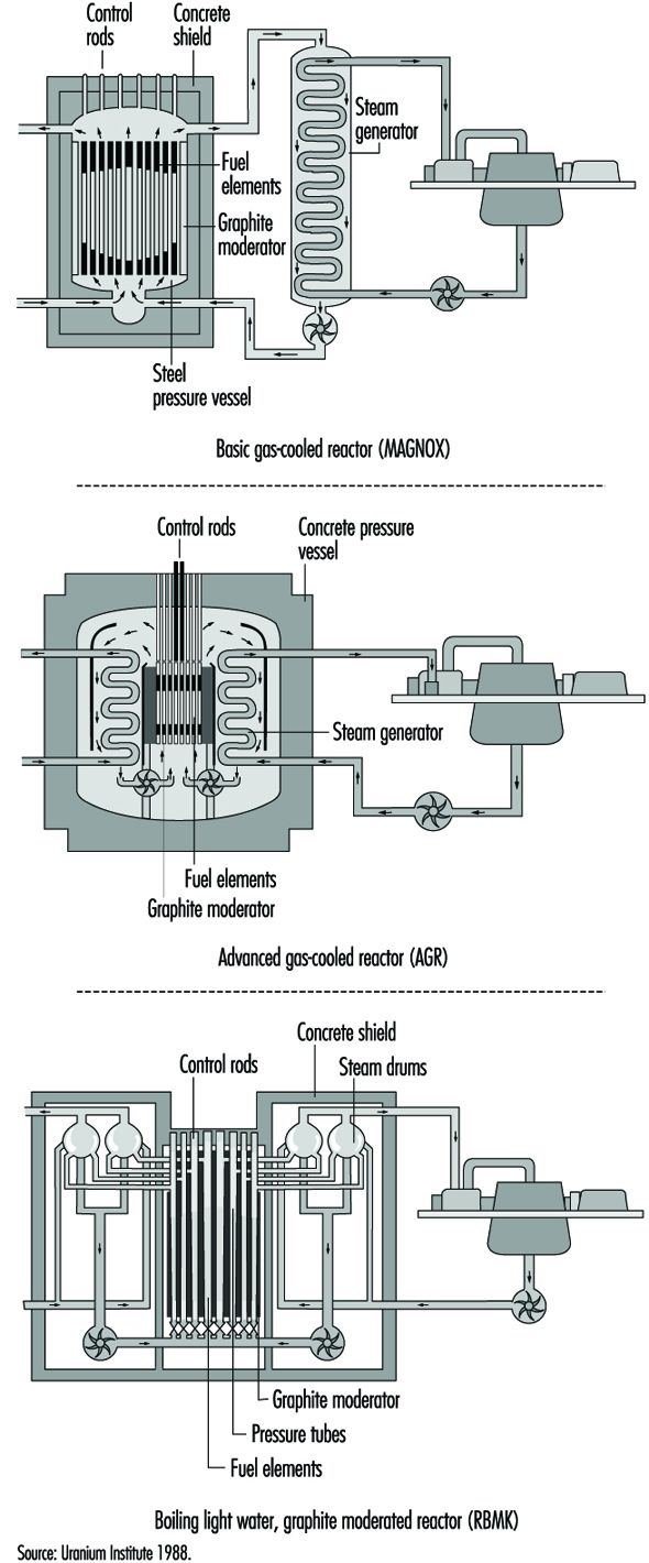
Table 1. Nuclear power station characteristics (1997)
|
Reactor type |
Fuel |
Moderator |
Coolant and its approx. pressure |
Steam generation |
No. of |
Net output |
|
PWR |
Enriched uranium dioxide |
Light water |
Light water |
Indirect |
251 |
223,717 |
|
PHWR (CANDU type) |
Unenriched uranium dioxide |
Heavy water |
Heavy water |
Indirect |
34 |
18,927 |
|
BWR |
Enriched uranium dioxide |
Light water |
Light water |
Direct |
93 |
78,549 |
|
GCR (MAGNOX type) |
Unenriched uranium metal |
Graphite |
Carbon dioxide |
Indirect |
21 |
3,519 |
|
AGR |
Enriched uranium dioxide |
Graphite |
Carbon dioxide |
Indirect |
14 |
8,448 |
|
LWGR (RBMK type) |
Enriched uranium dioxide |
Graphite |
Light water |
Direct |
18 |
13,644 |
|
FBR |
Mixed oxide plutonium |
None |
Sodium |
Indirect |
3 |
928 |
In a pressurized water reactor (PWR) power station, the reactor primary coolant and moderator are the same—purified ordinary water, which is separated from the secondary feedwater/steam circuit by a metallic boundary in steam generators (sometimes called boilers), through which the heat is transferred by conduction. The steam fed to the turbine-generator is therefore not radioactive, and the steam turbine-generator plant can be operated like a conventional power plant. Because hydrogen in the primary coolant/moderator water absorbs a significant fraction of the neutrons, it is necessary to enrich the fuel’s fissile uranium-235 isotope content to between 2% and 5% to sustain a practical chain reaction for long-term power production.
In all operating nuclear power stations with pressurized heavy water reactors (PHWRs), the reactor moderator and primary coolant is heavy water with a very high isotopic deuterium content (>99%). In the CANDU PHWR, which constitutes almost all the operating PHWRs, the moderator is separated from the primary coolant and held at relatively low temperature and pressure, which provides a convenient environment to locate monitoring and control instrumentation, and a built-in back-up cooling capability in the event of primary coolant piping failure. The fuel and primary coolant in the CANDU are in horizontal pressure tubes in the reactor core. As in the PWRs, the primary coolant and secondary feedwater/steam circuit are separated by a metallic boundary in steam generators, through which the heat is transferred from the primary heavy water to the ordinary water steam-feedwater system. The steam fed to the turbine generator plant is therefore ordinary water steam, not radioactive (except for small amounts due to leaks), and the turbine-generator plant can be operated like a conventional thermal power plant. The heavy water moderator and coolant absorbs only a very small fraction of the neutrons generated during fission, allowing a practical chain reaction for long-term power production using natural uranium (0.071% uranium-235). Existing PHWRs can operate with slightly enriched uranium-235 fuel, which results in proportionately greater total energy extraction from the fuel.
In a boiling water reactor (BWR) nuclear power station, the primary cooling water is partially evaporated in the reactor core itself, and the steam generated there is fed directly to the turbine-generator. The operating pressure in the reactor is lower than that in the PWRs, but the steam pressure fed to the turbine is similar. The steam fed to the turbine is slightly radioactive, requiring some precautions because of the potential low-level contamination of the turbine/feedwater system. However, this has not proven to be an important factor in operation and maintenance of BWRs. In BWRs the control of reactor power is affected by the amount of steam in the core, and this has to be offset by appropriate control of the rate of coolant flow or reactivity insertions as the power level of the reactor is changed.
Magnox reactors, also known as gas cooled reactors (GLRs), are fuelled with natural uranium metal clad in magnesium. They are cooled by carbon dioxide at modest pressure, but generate relatively high-temperature steam, which gives good thermal efficiency. They have large cores with low power densities, so that the pressure vessels, which also act as the only containment structures, are also large. The pressure vessels in the early Magnox reactors were steel. In the later Magnox reactors a prestressed concrete vessel contained both the reactor core and the steam-raising heat exchangers.
Advanced gas-cooled reactors (AGRs) use enriched uranium oxide fuel (2.3% U-235). They are cooled by carbon dioxide at higher pressure than the Magnox reactors, and have improved heat transfer and thermal efficiency. The greater core power density in the AGRs compared to the Magnox reactors allows the AGR reactor to be smaller and more powerful. The prestressed concrete pressure vessel, which contains both the reactor core and the steam raising heat exchangers, also acts as the containment structure.
Light water graphite reactors (LWGRs) are a hybrid of different nuclear power systems. The only power stations of this type in operation today are the RBMK reactors located in the former Soviet Union, that is, in Russia, Ukraine and Lithuania. In the RBMK reactors the ordinary water coolant flows upward through vertical coolant channels (tubes) which contain the fuel, and boils within the core. The steam produced in the core is fed directly to the turbine-generator as in a BWR. The graphite moderator which surrounds the coolant channels operates at a temperature sufficiently above that of the coolant so that the heat generated in the graphite by moderating the neutrons is removed by the coolant channels. The RBMK reactors are large and have many coolant channels (>1,500).
Fast breeder reactors (FBRs) require enrichment of fissile material in the range of 20% and can sustain the fission chain reaction primarily by absorbing the fast neutrons produced in the fission process. These reactors do not need a moderator to slow down the neutrons, and can use excess neutrons to breed plutonium-239, a potential fuel for reactors. They can produce more fuel than they consume. While a number of these reactors were built to produce electricity in nine countries around the world, technical and practical difficulties related to the use of liquid metal coolants (sodium) and the very high heat rates has caused interest to wane. There are now only three or four relatively small liquid metal fast breeder reactors (LMFBRs) in service as power producers in the world, producing a total of less than 1,000 megawatts of electric power (MWe), and they are being phased out of service gradually. The technology of breeding reactors, however, has been considerably developed and documented for future use if ever required.
Fuel and Fuel Handling
The process that begins with mining uranium-bearing ore and ends with the final disposal of the used fuel and all fuel processing wastes is usually called the nuclear fuel cycle. There are many variations in fuel cycles, depending on the type of reactor involved and the design of the heat removal arrangements in the reactor core.
The basic PWR and BWR fuel cycles are nearly identical, varying only in the levels of enrichment and the detailed design of the fuel elements. The steps involved, usually at different locations and facilities, are:
- uranium mining and milling to produce yellowcake (U3O8)
- uranium conversion to uranium hexafluoride (UF6)
- enrichment
- fuel fabrication, which involves uranium conversion to uranium dioxide (UO2), fuelled pellet production, fuel rod manufacture in lengths equal to the reactor core height, and manufacture of fuel assemblies containing about 200 fuel rods per assembly in a square array
- installation and operation in a nuclear power plant
- either reprocessing or temporary storage
- shipment of used fuel or enrichment waste to a federal/central repository
- eventual disposal, which is still in the development stage.
Precautions are required during these processes to ensure that the amount of enriched fuel at any location is less than that which could result in a significant fission chain reaction, except, of course, in the reactor. This results in material space restrictions in manufacture, shipping and storage.
In contrast, the CANDU reactor uses natural uranium, and has a simple fuel cycle from mining the ore to fuel disposal, which does not include the steps involved to provide enrichment and reprocessing. The fuel for the CANDU is manufactured semi-automatically in half-metre long round bundles of 28 or 37 fuel rods containing UO2 pellets. There are no space restrictions in manufacturing natural uranium fuel, or in shipping or storing either the new or used fuel. The immobilization and disposal of used CANDU fuel has been under development for 17 years in Canada, and is currently in the concept approval stage.
In all operating power reactors, with the exception of the Magnox type, the basic component of the reactor fuel is the cylindrical fuel pellet, composed of uranium dioxide (UO2) powder which is compacted and then sintered to attain the required density and ceramic characteristics. These sintered pellets, which are sealed in seamless zirconium alloy or stainless steel tubing to produce fuel rods or elements, are chemically inert with respect to their cladding at normal reactor temperatures and pressures. Even if the cladding is damaged or breached and the coolant comes in contact with the UO2, this ceramic material retains most of the radioactive fission products and resists deterioration caused by the high-temperature water.
The Magnox reactors use natural uranium metal fuel clad in magnesium, and operate successfully at relatively high temperatures, because the coolant, carbon dioxide, does not react with these metals under dry conditions.
The basic objective of the design of the fuel rods in a nuclear reactor is to transfer the fission heat generated in the fuel to the coolant, while maintaining the integrity of the fuel rods even under the most severe transient conditions. For all operating reactors, extensive testing of simulated fuel in heat transfer laboratories has demonstrated that the anticipated maximum in-reactor heat transient condition can be accommodated with adequate safety margins by the specific fuel designed and licensed for the application.
New fuel delivered from the fabrication plant to the power station is not significantly radioactive, and can be handled manually or by manually operated lifting/handling tools, without shielding. A typical fuel assembly for a PWR or BWR reactor is a square array of about 200 fuel rods, about 4 m long, weighing about 450 kg. About 200 of these assemblies are required in a large PWR or BWR reactor. The fuel is handled by overhead crane and placed in vertical racks in the dry in the new fuel storage area. To install new fuel in an in-service light-water reactor such as a PWR or BWR, all operations are conducted under a sufficient depth of water to provide shielding for anyone above the reactor. The flanged lid of the reactor vessel must first be removed and some of the used fuel taken out, (usually one-third to one-half reactor core), by overhead crane and fuel-handling elevators.
The used fuel is placed in water-filled storage bays. Other used fuel assemblies in the core may be rearranged in position (generally moved toward the centre of the core), to shape the power production in the reactor. New fuel assemblies are then installed in all vacant fuel site positions. It may require from 2 to 6 weeks to refuel a larger reactor, depending on the workforce and the amount of fuel to be replaced.
The CANDU reactor and some gas-cooled reactors are fuelled on-power by remote-operated equipment which removes used fuel and installs new fuel elements or bundles. In the case of the CANDU, the fuel is half-metre-long bundles of fuel rods, approximately 10 cm in diameter and weighing about 24 kg. The fuel is received from the manufacturer in cardboard packing cases and stored in a designated new-fuel storage area, ready to load into the reactor. Fuel is generally loaded into an operating reactor on a daily basis to sustain the reactivity of the reactor. In a large CANDU reactor, 12 bundles per day is a typical refuelling rate. The bundles are loaded by hand onto a new-fuel loading device which in turn loads the bundles into a fueling machine which is controlled remotely from the station control room. To load new fuel into a reactor, two remote-operated fuelling machines are manoeuvred by remote control and coupled onto the ends of the horizontal fuel channel to be refuelled. The channel is opened by the fuelling machines at both ends while the cooling system is at operating pressure and temperature, and new fuel is pushed in one end and used fuel is withdrawn from the other end of the channel. When the required number of fuel bundles have been installed, the channel seals are re-installed by the fuelling machine, and the fuelling machines may go on to refuel another channel or to discharge the used fuel into the used-fuel water-filled storage bay.
The used fuel discharged from all operating reactors is very radioactive and requires cooling to prevent overheating, and shielding to prevent direct irradiation of any sensitive living organisms or equipment nearby. The usual procedure is to discharge the used fuel into a water-storage pool with at least 4 m of water coverage over the fuel for shielding. This allows safe observation of the fuel through the water, and access for moving it under water to a more long-term storage location.
One year after discharge from a reactor, the overall radioactivity and heat generation from used fuel will decrease to about 1% of its initial value on discharge, and within 10 years to about 0.1% of its initial value at discharge. After about 5 to 10 years from discharge, the heat production has decreased to the point that it is feasible to remove the fuel from the water pool and store it in the dry form in a container with only natural circulation of air around the fuel container. However, it is still quite radioactive, and shielding of its direct radiation is required for many decades. Prevention of ingestion of the fuel material by living organisms is required for a much longer period.
The actual disposal of used fuel from power reactors is still in the development and approval stages. Disposal of used fuel from power reactors in various geologic structures is being studied intensely in a number of countries, but has not as yet been approved anywhere in the world. The concept of storage deep underground in stable rock structures is now in the approval process in Canada as a safe and practical method of finally disposing of these high-level radioactive wastes. However, it is anticipated that even with concept approval by the year 2000, the actual disposal of used fuel will not take place until about 2025.
In-plant Operations
In all 33 countries with nuclear power programmes, there are regulatory bodies that establish and enforce safety regulations related to the operation of nuclear facilities. However, it is generally the power utility which owns and operates nuclear power facilities that is held responsible and liable for the safe operation of its nuclear power plants. The role of the operator is really a management task of information gathering, planning and decision making, and only occasionally includes a more active control when routine operation is disrupted. The operator is not the primary protective system.
All modern nuclear power plants have highly reliable automatic, very responsive control and safety systems which protect the reactor and other plant components continuously, and which are generally designed to be fail-safe on loss of power. The operator is not expected to duplicate or substitute for these automatic control and protective systems. The operator, however, must be able to shut down the reactor almost instantly if necessary, and should be capable of recognizing and responding to any aspect of plant operation, thus adding to the diversity of protection. The operator needs the ability to understand, diagnose and anticipate the development of the overall situation from a large amount of data provided by the automatic data and information systems.
The operator is expected to:
- understand what the normal conditions are in all systems relevant to the current overall status of the plant
- recognize, with help from the automatic systems or special monitoring devices, when abnormal conditions arise, and their significance
- know how to respond correctly to restore the plant to normal operation, or bring the plant to a safe shutdown condition.
How well the operator can do this depends on the design of the machine as well as the operator’s ability and training.
Every nuclear power station must have competent, stable and well-trained operators on duty at all times. Potential nuclear operators undergo a comprehensive training programme, which usually includes classroom and on-the-job training in science, equipment and power systems, radiation protection and operating policies and principles. Training simulators are always used in US utility nuclear plant operation to provide the operator with hands-on experience in plant operations, during upsets and in unusual conditions. The interface between the operator and the power systems is through the control room instrumentation. Well-designed instrumentation systems can improve the understanding and proper response of the operators.
It is usual to appoint the key operating staff for a nuclear power station while it is still under construction, so they can advise from an operating point of view, and can assemble staff who will commission and operate the station. They also prepare a comprehensive set of operating procedures before the station is commissioned and allowed to operate. Design experts and regulatory personnel inspect these procedures for consistency of design intent and operating practices.
The staff are expected to operate the station systematically and rigorously in accordance with the operating procedures and work authorizations. The operating staff continually work to ensure public safety by conducting a comprehensive programme of testing and monitoring the safety systems and protective barriers, and by maintaining the ability to deal with any plant emergency. Where operators may have to take action in response to an alteration in the state of the plant, there are written, systematic procedures to guide them and to provide the detailed information needed to control the plant. Such procedures are reviewed by station and regulatory safety committees.
A well-thought-out operation safety management programme includes:
- detailed knowledge of areas critical to safety
- standards or targets that define acceptable performance
- a programme for monitoring performance, responding to problems and reporting results
- an experience review programme to establish trends, the degree of compliance with standards and the cause of any unacceptable or deteriorating performance
- a means of assessing the impact of proposed changes to hardware or operating procedures and implementing changes consistent with the accepted standard.
In addition to procedures for normal operation, there is an event-reporting system at each nuclear power station to investigate and document any failures and deterioration of equipment, shortcomings in design or construction, and operating errors detected by monitoring systems or regular tests and inspections. The basic cause of each event is determined so that the appropriate corrective or preventive action can be developed. Event reports, including the results of the analysis and recommendations, are reviewed by the station management and by experts in safety and human factors, who are usually based off the station site.
The International Atomic Energy Agency’s (IAEA) Incident Reporting System operates around the world to complement the national systems and ensure that information is shared among all participating countries. The World Association of Nuclear Operators (WANO) also provides a detailed information exchange at the operational level.
Nuclear reactors and all their auxiliary and safety-related systems are maintained and tested according to quality assurance requirements at planned intervals, to ensure reliability throughout their service life. In addition to automatic monitoring, there are systematic manual tests and investigations for evidence of impairment or failure of equipment systems. These include regular field surveillance, preventive maintenance, periodic tests and the study of changes in plant conditions.
Very demanding performance targets are set for process and safety systems to keep the risk to the public and station staff acceptably small. For process systems, which are actively operating while electricity is being generated, failure rates are compared to performance targets, which may result in design changes where performance is substandard. Safety systems need a different approach, because they come into operation only if process systems fail. Comprehensive test programmes monitor these systems and their components, and the results are used to determine how much of the time each of them would likely be out of service. The total amount of time the safety systems are calculated to be out of service is compared to a very high performance standard. If a deficiency is detected in a safety system it is put right immediately or the reactor is shut down.
There are also extensive tests and maintenance programmes during periodic scheduled shutdowns. For example, all pressure-bearing vessels, components and their welds are systematically inspected by non-destructive methods according to safety code regulations.
Safety Principles and Related Safety Design Features
There are four aspects of the fission chain reaction which could be dangerous and which cannot be separated from the use of nuclear energy to produce electricity, and therefore require safety measures:
- Fission results in ionizing radiation, which requires shielding from direct exposure to radiation.
- Highly radioactive fission products are created, requiring tight enclosures to prevent contamination of the external environment and possible ingestion.
- The fission chain reaction is a dynamic process requiring continuous control.
- The heat production cannot be instantly stopped, since radioactive decay continues to produce heat after the fission chain reaction is terminated, requiring long-term cooling.
The safety requirements which these characteristics demand account for the major differences in safety equipment and operating strategy in a nuclear station compared to those in a power-generating station utilizing fossil fuel. How these safety requirements are fulfilled differs for different types of nuclear stations, but the fundamental safety principles are the same in all nuclear stations.
During the licensing procedure, each nuclear installation has to prove that radioactive releases will be less than specified regulatory limits, both during normal operating conditions and in the event of faults or accident conditions. The priority is to prevent failures rather than simply to mitigate their consequences, but the design has to be capable of dealing with failures if, in spite of all precautions, they do occur. This requires the highest degree of quality assurance and control, applied to all equipment, construction functions and operations. Inherent safety characteristics and engineered safety measures are designed to prevent and control accidents and contain and minimize the release of radioactive materials.
In particular, the heat generation and cooling capacity must be matched at all times. During operation, heat is removed from the reactor by a coolant, which is pumped through piping connected to the reactor, and flows over the fuel cladding surface. In the event of loss of power to the pumps or sudden failure of the connecting piping, cooling of the fuel would be interrupted, which could result in a rapid rise in the temperature of the fuel, possible failure of the fuel cladding, and escape of radioactive material from the fuel to the reactor vessel. A rapid shutdown of the fission chain reaction, backed up by possible activation of standby or emergency cooling systems, would prevent fuel damage. These safety measures are provided in all nuclear stations.
Even when the reactor has been shut down, loss of cooling and failure of the standby or emergency cooling capability could result in overheating of the fuel because of the continuing fission product decay heat production in the fuel, as indicated in figure 2. While the decay heat is only 1% or 2% of the full-power heat production, if it is not removed, the fuel temperature could reach failure levels within minutes of complete loss of cooling. The principle of nuclear power plant safety design requires that all circumstances that could lead to fuel overheating, damage and release of radioactive materials from the fuel are carefully assessed and prevented by engineered control and protective systems.
Figure 2. Decay heat after reactor shutdown

To protect a nuclear power station, there are three kinds of safety features: inherent characteristics, passive systems and active systems. These are used in various combinations in operating nuclear stations.
Inherent safety characteristics make use of the laws of nature to keep the power plant safe. There are inherent safety characteristics of some nuclear fuels such that, as their temperature rises, the fission chain reaction rate is slowed. There are inherent safety characteristics with some designs of cooling systems whereby the coolant will circulate over the fuel by natural circulation to adequately remove the decay heat without operation of any pumps. There are inherent safety characteristics in most metallic structures that result in yielding or stretching under severe loads rather than bursting or failure.
Passive safety features include the lifting of dead weight (gravity) relief valves by the pressure of the fluid to be relieved, or in the use of stored energy in emergency coolant injection systems, or in some containment vessels which are designed to accommodate the energy from failure of piping systems and subsequent decay heat.
Active safety systems include all systems which require activating signals and a power supply of some form. Active systems can generally control a wider range of circumstances than inherent and passive systems, and can be tested without restrictions during operation of the reactor.
The safety design of nuclear power stations is based on a selected combination of inherent, passive and active systems to meet the regulatory safety requirements of the jurisdiction in which the nuclear station is located. A high degree of automation in safety-related systems is necessary to relieve operations personnel, as much as possible, of the need to take quick decisions and actions under stress. Nuclear power reactor systems are designed to adjust to changes in demanded power output automatically, and generally changes are gradual. It is particularly important that safety-related systems be continuously capable of responding promptly, effectively and reliably when required. To meet this high level of performance these systems must comply with the highest quality assurance criteria and be designed to the well established safety design principles of redundancy, diversity and physical separation.
Redundancy is the provision of more components or subsystems than are needed to just make the system work—for example, providing three or four components where only two are needed to function for the system to perform properly.
Diversity is the provision of two or more systems which are based on different design or functional principles to perform the same safety function.
Physical separation of components or systems which are designed to perform the same safety function, provides protection against local damage which could otherwise impair the performance of the safety systems.
An important illustration of the application of these safety design principles is in the electric power supply in nuclear stations, which is based on more than one connection to the main power system, backed up on site by several automatic-start diesels and/or combustion turbines, and by banks of batteries and motor-generator sets to ensure the reliable supply of electricity to the vital safety-related systems.
The basic preventive measure against release of radioactive materials from a nuclear station is very simple in principle: a series of leak-tight barriers between the radioactive materials and the environment, in order to provide shielding against direct radiation and containment of the radioactive materials. The innermost barrier is the ceramic or metallic fuel itself, which binds most of the radioactive materials within its matrix. The second barrier is the leak-tight, corrosion-resistant cladding. The third barrier is the primary pressure-bearing boundary of the coolant system. Finally, most nuclear power systems are enclosed in a pressure-resistant containment structure which is designed to withstand failure of the largest piping system within and to contain any radioactive materials released into containment.
The basic aim of the nuclear power station safety design is to maintain the integrity of these multiple barriers by a defence-in-depth approach which can be characterized by three levels of safety measures: preventive, protective and mitigative measures.
Preventive measures include: meeting the highest level of quality assurance during design, construction and operation; highly trained operators who undergo periodic retraining; utilizing inherent safety features; providing appropriate design margins; undertaking careful preventive maintenance, continual testing and inspection and correction of deficiencies; constant monitoring; thorough safety assessments and reassessments when required; and evaluation and causal analysis of incidents and faults, making appropriate modifications.
Protective measures include: fast-acting shut-down systems; responsive automatic pressure-relief valves/systems; interlock circuits to protect against false operation; automatic monitoring of vital safety functions; and continuous measurement and control of radiation levels and effluent radioactivity so as not to exceed allowable limits.
Mitigative measures include: emergency reactor cooling systems; highly reliable emergency feedwater systems; diverse and redundant emergency power systems; containment to prevent any radioactive materials leaking from the station, which is designed for a variety of natural and artificial stresses such as earthquakes, high winds, floods or aircraft impingement; and, finally, emergency planning and accident management, which includes radiation monitoring, informing safety authorities and advising the public, control of contamination and distribution of mitigating materials.
Nuclear safety does not only depend on technical and scientific factors; human factors play a very important role. Regulatory control provides an independent verification of all safety aspects of nuclear stations. However, nuclear safety is primarily ensured not by laws and regulations, but by responsible design, operation and utility management, which includes appropriate reviews and approvals by those with knowledge and authority.
The only nuclear station accident to have very serious consequences for the public occurred during a test of cooling capability in an unusual configuration in a RBMK nuclear station at Chernobyl in Ukraine in 1986. In this severe accident the reactor was destroyed and a large amount of radioactive materials escaped to the environment. It was subsequently found that the reactor did not have an adequate shut-down system and that it was unstable at low power. Design weaknesses, human error and lack of proper utility management all contributed to the accident. Modifications have been made to the remaining operating RBMK reactors to eliminate serious design weaknesses, and operating instructions have been improved to ensure there will not be a repeat of this unfortunate accident.
Much has been learned from the RBMK accident and from other less serious nuclear station accidents (such as the Three Mile Island accident in the United States in 1978) and from many minor accidents and incidents over more than 30 years of nuclear power station operation. The goal of the nuclear community is to ensure that no nuclear power station incident endanger the workers, the public or the environment. Close cooperation under such programmes as the IAEA Incident Reporting Systems and WANO, the scrutiny of industry groups and regulatory agencies, and vigilance by nuclear stations owners and operators, make this goal more attainable.
Acknowledgement: The editor thanks Tim Meadler and the Uranium Institute for providing information for table 1.
Electric Power Generation, Transmission and Distribution Safety: A US Example
Generation, Transmission and Distribution
There are three stages of electric power supply; generation, transmission and distribution. Each of these stages involves distinct production processes, work activities and hazards.
Most electricity is generated at 13,200 to 24,000 volts. The hazards of the electrical power generation process include explosions and burns resulting from unexpected equipment failure. Accidents can also occur when proper lockout/tagout procedures are not followed. These procedures are in place to control energy sources. Before performing maintenance on equipment where the unexpected energizing, start up or release of stored energy could occur and cause injury, the equipment must be isolated from the energy source and rendered inoperative. Failure to properly isolate these energy sources (lockout/tagout) can result in serious injury or death.
After electrical power is generated, it is transmitted over distances using transmission lines. Transmission lines are constructed between transmission substations located at electric generating stations. Transmission lines may be supported overhead on towers or they may be underground. They are operated at high voltages. They send out large amounts of electrical power and extend over considerable distances. When electricity comes out of a generating station, the transmission substation located there steps up the voltages to the range of 138,000–765,000 volts. Within the operating area, transmission substations reduce the transmitted voltage to 34,500–138,000 volts. This power is then carried through lines to the distribution systems located in the local service territory. The major hazards present during the transmission process are electrical. Failure to maintain proper approach distances or use appropriate protective equipment (rubber gloves and sleeves) can result in serious injury or death. Falls also are a source of serious accidents and can occur during maintenance work on overhead lines and while working from poles or bucket trucks.
The distribution system connects the transmission system to the customer’s equipment. The distribution substation reduces the transmitted electrical voltage to 2,400–19,920 volts. A distribution transformer further reduces the voltage. Hazards related to distribution work also are electrical in nature. However, there is the additional hazard of working in enclosed spaces (manholes and vaults) when dealing with an underground distribution system.
Transmission and distribution substations are installations where the voltage, phase or other characteristics of the electrical energy are changed as part of the final distribution process. Electrocutions represent the primary safety hazard in substations. Such accidents are generally caused by failure to maintain proper approach distances to live electrical equipment and/or failure to use appropriate personal protective equipment, including rubber insulating gloves and sleeves.
Safety Hazards of Generation, Transmission and Distribution
The Electric Power Generation, Transmission and Distribution Standard, also known as the Electric Maintenance Standard Codified at 29 CFR 1910.269, was promulgated by the US Occupational Safety and Health Administration (OSHA) on 31 January 1994. The Standard covers all electric utility workers involved in the operation and maintenance of electric power generation, transmission and distribution equipment and associated equipment. In addition, contract lineworkers, contract line clearance tree trimmers and independent power producers are also covered by the provisions of 1910.269. Other countries and regions have similar regulations.
The hazards that are directly addressed by the OSHA standard are those of an electrical nature which would cause electrocution and injuries resulting from electric shock. The consequences of inadvertent contact with high-voltage electricity are often death or serious injuries such as second- and third-degree burns, amputation of limbs, damage to internal organs and neurological damage.
The standard also addresses fatalities and injuries associated with four other types of accidents—struck by or struck against; falls from ladders, scaffolds, poles or other elevations; caught in or between as a result of the accidental activation of machinery during routine maintenance work; and contact with temperature extremes which can occur when high-pressure steam is inadvertently released during maintenance work on boilers. The Eastern Research Group (ERG), who prepared the Economic Impact Study for the proposed OSHA regulation, reported that “there were more accidents associated with transmission and distribution lines than with substations or power generation installations”. ERG reported that in the transmission and distribution line category, line workers, apprentice line workers and working line supervisors experience the most fatal and serious lost-time accidents. Within the substation and power generation category, substation electricians and general utility mechanics experience the most accidents.
Accident Reduction
OSHA has estimated that in the United States an average of 12,976 lost workday injuries occur annually to electric power generation, transmission and distribution employees. They also report that 86 fatalities occur to these workers annually. OSHA estimates that 1,633 lost workday injuries and 61 deaths can be prevented annually through compliance with the provisions of this standard and the other standards referenced in the final rule. OSHA breaks down the reduction in lost-workday injuries and fatalities into two categories. The greatest benefit is expected to be achieved in the electric utilities, which account for approximately 80% of the fatalities. Utility contractors, including electrical contractors and line clearance tree trimmers, and non-utility establishments account for the other 20%. OSHA also expects the greatest reduction in lost workday injuries to be experienced by the electric utilities. The second category of reduction relates to the referencing of existing standards within 1910.269. For example, OSHA expects the employer to provide medical services and first aid as specified in 1910.151.
Excavation operations shall comply with Subpart P of 1926; personal protective equipment shall meet the requirements of Subpart I of 1910; personal fall-arrest equipment shall meet the requirements of Subpart E of Part 1926; and ladders shall comply with Subpart D of 1910. These are a few examples of the many other OSHA standards referenced in the Electric Power Generation, Transmission and Distribution Standard. OSHA believes that these references will foster an increased recognition of the various applicable safety standards and, together with employee training and emphasis on hazard recognition through job briefings, an additional 2 fatalities and 1,310 lost-workday injuries will be prevented annually.
General Provisions
The Electric Power Generation, Transmission, and Distribution Standard provides a comprehensive approach for the control of hazards found in the electric utility industry. This is considered a performance-based standard, where the employer has the opportunity to implement alternative programmes provided he or she can demonstrate that they provide a level of safety equivalent to that specified in the standard. General provisions of the standard include: training requirements, hazardous energy control (lockout/tagout) procedures for power generation, transmission and distribution; enclosed space entry procedures and procedures for working safely in underground installations; requirements for working on or near exposed energized parts; requirements for working on overhead lines; grounding requirements; line clearance tree trimming; procedures for working in substations; and requirements for live-line tools, hand and portable power tools, and ladders and personal protective equipment.
The standard is comprehensive and addresses all aspects of the operation and maintenance of power generation, transmission and distribution equipment.
Significant Provisions
Some of the most significant provisions of the Standard include requirements for employees to have emergency aid training, job briefings, and training in safety-related work practices, safety procedures, and emergency procedures including manhole and pole-top rescue. There are also specific clothing requirements for working on energized equipment, and requirements for entry into underground structures, as well as the control of hazardous energy sources. Another significant element of the standard requires employers to certify that employees have been appropriately trained and can demonstrate proficiency in the work practices specified in the standard. A few of these elements are discussed in more detail below.
OSHA requires that employees performing work on or associated with exposed lines or equipment energized at 50 volts or more be trained in first aid and cardiopulmonary resuscitation (CPR). For field work involving two or more employees at a work location, at least two employees shall be trained. For fixed work locations such as a generating station, a sufficient number of employees must be trained to ensure that an employee exposed to electric shock can be reached within 4 minutes.
The lead employee in a work group must conduct a job briefing with the employees involved in the work before they start each job. The briefing must cover the hazards associated with the job, work procedures involved, special precautions, energy source controls and personal protective equipment. For repetitive and similar jobs there must be one job briefing before the start of the first job of each day or shift. When significant changes occur, another briefing must be conducted. Reviewing the task at hand requires job planning, and job planning helps to reduce accidents.
OSHA also has required that the employer certify that each employee has received the training required to be qualified and competent. The certification shall be made when the employee demonstrates proficiency in the work practices, and shall be maintained for the duration of an employee’s employment. Training alone is inadequate. Proficiency must be demonstrated, generally through testing an employee’s knowledge and understanding of the subject at hand. This will help ensure that only qualified workers work on energized equipment.
There are clothing requirements for workers who are exposed to the hazards of flames or electric arcs. The section requires that the employer ensure that each employee who is exposed to the hazards of flames or electric arcs not wear clothing that, when exposed to flames or electric arcs, could increase the extent of injury that would be sustained by the employee. Clothing made from acetate, nylon, polyester or rayon, either alone or in blends, is prohibited unless the employer can demonstrate that the fabric has been treated to withstand the condition that may be encountered. Employees may choose among cotton, wool or flame-retardant clothing, but the employer must determine, based on the exposure, whether or not a natural fibre such as cotton or wool is acceptable. Cotton or wool could ignite under certain circumstances. Although this section of the standard has caused much controversy throughout the industry, prohibiting the use of synthetics is a significant step towards reducing injuries to electrical workers.
Hazards
OSHA in its preamble to the Electric Power Generation, Transmission and Distribution Standard (29 CFR Part 1910.269) states that “overall accident incidence rates for the electric services industry (that is, the electric utility industry, SIC-491) are slightly lower than corresponding rates for the private sector as a whole” and that “except for electrical and fall hazards, electric utility employees face hazards that are similar in nature and degree to those encountered in many other industries” (OSHA 1994).The preamble goes on to cite US Bureau of Labor Statistics (BLS) files identifying the major sources of injury for electric utilities:
- falls
- overexertion
- being “struck by or against an object”, leading to sprains and strains, cuts, lacerations and contusions/bruises.
The preamble specifically notes that electric shock does not constitute a major (or frequently reported) injury category. However, labour, industry and OSHA files reveal that electrical accidents are the most frequent type of fatal or serious injuries in the electrical utility industry, followed by motor vehicle accidents, falls and “struck by/crushed.”
Many other hazards confront electrical utility workers in performing the varied tasks required by employers. The authors of individual articles in this chapter note many of these in detail; here I will simply mention some of the hazardous exposures.
Musculoskeletal injuries are the most common injuries occurring in this physically active workforce and include:
- vibration white fingers due to jackhammer use
- whiplash due to motor vehicle accidents
- low-back sprain
- head injury
- foot and ankle trauma
- torn medial meniscus.
Electrical workers can work in a wide variety of environments: they climb to the top of rural transmission towers and splice cables in manholes under busy city streets; they swelter on the top floors of the power stations in summer and shiver as they repair overhead distribution lines downed by a blizzard. The physical forces that confront the workers are enormous. A power plant, for example, pushes steam under such pressure that a ruptured pipe may mean scalding and suffocation. Physical hazards in plants in addition to heat include noise, electromagnetic fields (EMF), ionizing radiation in nuclear facilities and asphyxiation in confined spaces. Asbestos exposure has been a major source of morbidity and litigation, and concerns are being raised about other insulating materials. Chemicals such as caustics, corrosives and solvents are widely used. Plants also employ workers in specialized jobs like fire-fighting or scuba diving (to inspect water intake and discharge systems), who are exposed to the unique hazards intrinsic to those tasks.
While modern nuclear power stations have reduced workers’ radiation exposure during normal operating periods, substantial exposure may occur during maintenance and refuelling shut-downs. Excellent radiation monitoring capabilities are required to properly protect workers entering radiation areas during these periods. The fact that many contract workers may enter a nuclear plant during a shut-down and then move on to another plant, creates a need for close coordination between regulatory and industry authorities in monitoring the total annual exposure for an individual worker.
The transmission and distribution systems share some of the hazards of the power station, but also are characterized by unique work exposures. The enormous voltages and currents intrinsic to the system predispose to fatal electric shock and severe burns when workers ignore safety procedures or are inadequately protected. As transformers overheat, they may catch fire and explode, releasing oil and possibly PCBs and their breakdown products. Electrical substations share with power stations the potential of exposure to insulation, EMF and confined space hazards. In the distribution system, the cutting, burning and splicing of electrical cable expose workers to lead and other metals both as dusts and fumes. The underground structures which support the system must also be considered potential confined-space hazards. Pentachlophenol, a pesticide used to preserve wooden utility poles, is an exposure that is somewhat unique to the distribution system.
Finally, meter readers and outdoor workers may be exposed to street violence; fatalities in the course of robbery attempts are not unknown to this workforce.
Environmental and Public Health Issues
All human activity has an environmental impact. The magnitude and consequences of each impact varies, and environmental laws have been created to regulate and minimize these impacts.
Electrical power generation has several major potential and actual environmental hazards, including air emissions and water and soil contamination (table 1). Fossil fuel plants have been a particular concern because of their emissions into the air of nitrogen oxides (see “Ozone” below), sulphur oxides and the “acid rain” question, carbon dioxide (see “Global climate change” below) and particulates, which have recently been implicated as contributing to respiratory problems.
Table 1. Major potential environmental hazards of power generation
|
Type of plant |
Air |
Water* |
Soil |
|
Fossil fuel |
NO2 |
PCBs |
Ash |
|
SO2 |
Solvents |
Asbestos |
|
|
Particulates |
Metals |
PCBs |
|
|
CO |
Oil |
Solvents |
|
|
CO2 |
Acids/bases |
Metals |
|
|
Volatile organic compounds |
Hydrocarbons |
Oil |
|
|
Acids/bases |
|||
|
Hydrocarbons |
|||
|
Nuclear |
Same as above plus radioactive emission |
||
|
Hydro |
Chiefly leachate from soils to water behind dams Disturbance of wildlife habitat |
* Should include such “local” effects as increases in temperature of the body of water receiving plant discharges and reductions in fish population due to the mechanical effects of feedwater intake systems.
The concerns with nuclear plants have been with the long-term storage of nuclear waste, and the possibility of catastrophic accidents involving the release of radioactive contaminants into the air. The 1986 accident at Chernobyl, in Ukraine, is a classic example of what can happen when inadequate precautions are taken with nuclear plants.
With hydroelectric power plants, the main concerns have been leaching of metals and disturbance of both water and land wildlife habitats. This is discussed in the article “Hydroelectric power generation” in this chapter.
Electromagnetic Fields
Research efforts regarding electromagnetic fields (EMF) around the world have been growing since the study by Wertheimer and Leeper was published in 1979. That study suggested an association between childhood cancer and utility wires situated near homes. Studies since that publication have been inconclusive and have not confirmed causality. In fact, these subsequent studies have pointed to areas where greater understanding and better data are needed to be able to start to draw reasonable conclusions out of these epidemiological studies. Some of the difficulties of performing a good epidemiological study are related to the problems of assessment (i.e., the measurement of exposure, source characterization and levels of magnetic fields in the residences). Even though the most recent study released by the National Research Council of the National Academy of Sciences (1996) determined that there was not enough evidence to consider electric and magnetic fields threatening to human health, the issue will probably remain in the public’s eye until the widespread anxiety is alleviated by future studies and research which show no effect.
Global Climate Change
Over the past few years public awareness has increased concerning the impact that humans are having on the global climate. Approximately half of all greenhouse emissions from human activity are thought to be carbon dioxide (CO2). Much research on this issue on a national and international level has been and continues to be done. Because utility operations make significant contributions to the release of CO2 to the atmosphere, any rulemaking for the control of CO2 releases has the potential to impact the power generation industry in serious ways. The UN Framework Convention on Climate Change, the US Climate Change Action Plan and the Energy Policy Act of 1992 have created strong driving forces for the power industry to comprehend just how it might have to respond to future legislation.
Presently, some examples of the areas of study taking place are: the modelling of emissions, determining the effects of climate change, determining the costs associated with any climate change management plans, how humans might benefit by reducing greenhouse gas emissions, and predicting climate change.
A major reason for concern about climate change is the possible negative impacts on ecological systems. It is believed that systems that are not managed are the most sensitive and have the highest probability for significant impact on a global scale.
Hazardous Air Pollutants
The US Environmental Protection Administration (EPA) has sent to the US Congress an Interim Report on Utility Hazardous Air Pollutants, which had been required by the 1990 Clean Air Act Amendments. The EPA was to analyse the risks from fossil fuel-fired steam electric generating facilities. EPA concluded that these releases do not constitute a public health hazard. The report delayed conclusions about mercury pending additional studies. A comprehensive Electric Power Research Institute (EPRI) study of fossil-fired power plants indicates that greater than 99.5% of the fossil power plants do not yield cancer risks above the 1 in 1 million threshold (Lamarre 1995). This compares with the risk due to all emission sources, which has been reported to have been as high as 2,700 cases per year.
Ozone
Reduction of ozone levels in air is a major concern in many countries. Nitrogen oxides (NOx) and volatile organic compounds (VOCs) produce ozone. Because fossil fuel power plants contribute a large component of the world’s total NOx emissions, they can expect tighter control measures as countries tighten environmental standards. This will continue until the inputs for the photochemical grid models that are used for modelling tropospheric ozone transport are more accurately defined.
Site Remediations
Utilities are having to come to terms with the potential costs of manufactured gas plant (MGP) site remediation. The sites were originally created through the production of gas from coal, coke or oil, which resulted in onsite disposal of coal tar and other by-products in large lagoons or ponds, or in the use of offsite for land disposal. Disposal sites of this nature have the potential to contaminate groundwater and soil. Determining the extent of groundwater and soil contamination at these sites and the means to ameliorate it in a cost-effective manner will keep this issue unresolved for some time.
" DISCLAIMER: The ILO does not take responsibility for content presented on this web portal that is presented in any language other than English, which is the language used for the initial production and peer-review of original content. Certain statistics have not been updated since the production of the 4th edition of the Encyclopaedia (1998)."