- You are here:
-
Home

- Part XI. Industries Based on Natural Resources
Children categories

73. Iron and Steel (4)

73. Iron and Steel
Chapter Editor: Augustine Moffit
Table of Contents
Figures and Tables
Iron and Steel Industry
John Masaitis
Rolling Mills
H. Schneider
Health and Safety Problems and Patterns
Environmental and Public Health Issues
Tables
Click a link below to view table in article context.
1. Recoverable by-products of coke ovens
2. Waste generated & recycled in steel production in Japan
Figures
Point to a thumbnail to see figure caption, click to see figure in article context.


74. Mining and Quarrying (17)
74. Mining and Quarrying
Chapter Editors: James R. Armstrong and Raji Menon
Table of Contents
Figures and Tables
Mining: An Overview
Norman S. Jennings
Exploration
William S. Mitchell and Courtney S. Mitchell
Types of Coal Mining
Fred W. Hermann
Techniques in Underground Mining
Hans Hamrin
Underground Coal Mining
Simon Walker
Surface Mining Methods
Thomas A. Hethmon and Kyle B. Dotson
Surface Coal Mining Management
Paul Westcott
Processing Ore
Sydney Allison
Coal Preparation
Anthony D. Walters
Ground Control in Underground Mines
Luc Beauchamp
Ventilation and Cooling in Underground Mines
M.J. Howes
Lighting in Underground Mines
Don Trotter
Personal Protective Equipment in Mining
Peter W. Pickerill
Fires and Explosions in Mines
Casey C. Grant
Detection of Gases
Paul MacKenzie-Wood
Emergency Preparedness
Gary A. Gibson
Health Hazards of Mining and Quarrying
James L. Weeks
Tables
Click a link below to view table in article context.
1. Design air quantity factors
2. Clothing-corrected air cooling powers
3. Comparison of mine light sources
4. Heating of coal-hierarchy of temperatures
5. Critical elements/sub-elements of emergency preparedness
6. Emergency facilities, equipment & materials
7. Emergency preparedness training matrix
8. Examples of horizontal auditing of emergency plans
9. Common names & health effects of hazardous gases
Figures
Point to a thumbnail to see figure caption, click to see figure in article context.
|
|


75. Oil Exploration and Distribution (1)
75. Oil Exploration and Distribution
Chapter Editor: Richard S. Kraus
Table of Contents
Exploration, Drilling and Production of Oil and Natural Gas
Richard S. Kraus
Tables
Click a link below to view table in article context.
1. Properties & gasoline potential of crude oils
2. Composition of crude oil & natural gas
3. Composition of natural & oil processing gases
4. Platform types for underwater drilling
Figures
Point to a thumbnail to see figure caption, click to see figure in article context.


76. Power Generation and Distribution (7)
76. Power Generation and Distribution
Chapter Editor: Michael Crane
Table of Contents
Figures and Tables
General Profile
Michael Crane
Hydroelectric Power Generation
Neil McManus
Fossil Fuel Power Generation
Anthony W. Jackson
Nuclear Power Generation
W.G. Morison
Electric Power Generation, Transmission and Distribution Safety: A US Example
Janet Fox
Hazards
Michael Crane
Environmental and Public Health Issues
Alexander C. Pittman, Jr.
Tables
Click a link below to view table in article context.
1. Controlling chemical & biological hazards
2. Controlling physical & safety hazards
3. Nuclear power station characteristics (1997)
4. Major potential environmental hazards
Figures
Point to a thumbnail to see figure caption, click to see figure in article context.


Ventilation and Cooling in Underground Mines
The main objective of mine ventilation is the provision of sufficient quantities of air to all the working places and travel ways in an underground mine to dilute to an acceptable level those contaminants which cannot be controlled by any other means. Where depth and rock temperatures are such that air temperatures are excessive, mechanical refrigeration systems may be used to supplement the beneficial effects of ventilation.
The Mine Atmosphere
The composition of the gaseous envelope encircling the earth varies by less than 0.01% from place to place and the constitution of “dry” air is usually taken as 78.09% nitrogen, 20.95% oxygen, 0.93% argon and 0.03% carbon dioxide. Water vapour is also present in varying amounts depending on the air temperature and pressure and the availability of free water surfaces. As ventilation air flows through a mine, the concentration of water vapour may change significantly and this variation is the subject of the separate study of psychrometry. To define the state of a water vapour and dry air mixture at a particular point requires the three measurable independent properties of barometric pressure, dry bulb and wet bulb temperatures.
Ventilation Requirements
The contaminants to be controlled by dilution ventilation are primarily gases and dust, although ionizing radiations associated with naturally occurring radon may present problems, especially in uranium mines and where the background uranium concentrations of the host or adjacent rocks are elevated. The amount of air required for dilution control will depend on both the strength of the contaminant source and the effectiveness of other control measures such as water for dust suppression or methane drainage systems in coal mines. The minimum dilution air flow rate is determined by the contaminant requiring the greatest dilution quantity with due cognizance of the possible additive effects of mixtures and synergism where one contaminant can increase the effect of another. Overriding this value could be a minimum air velocity requirement which is typically 0.25 m/s and increasing as air temperatures also increase.
Diesel-powered equipment ventilation
In mechanized mines using diesel-powered mobile equipment and in the absence of continuous gas monitoring, exhaust gas dilution is used to determine the minimum ventilation air requirements where they operate. The amount of air required normally ranges between 0.03 and 0.06 m3/s per kW of rated power at the point of operation depending on the type of the engine and whether any exhaust gas conditioning is being used. Continuing developments in both fuel and engine technology are providing lower engine emissions while catalytic converters, wet scrubbers and ceramic filters may further reduce the leaving concentrations of carbon monoxide/aldehydes, oxides of nitrogen and diesel particulates respectively. This helps in meeting increasingly stringent contaminant limits without significantly increasing exhaust dilution rates. The minimum possible dilution limit of 0.02 m3/s per kW is determined by the carbon dioxide emissions which are proportional to engine power and unaffected by exhaust gas conditioning.
Diesel engines are about one-third efficient at converting the energy available in the fuel to useful power and most of this is then used to overcome friction resulting in a heat output which is about three times the power output. Even when hauling rock up a decline in a truck, the useful work done is only about 10% of energy available in the fuel. Higher diesel engine powers are used in larger mobile equipment which require bigger excavations to operate safely. Allowing for normal vehicle clearances and a typical diesel exhaust gas dilution rate of
0.04 m3/s per kW, the minimum air velocities where diesels operate average about 0.5 m/s.
Ventilation of different mining methods
Although the setting of general air quantity requirements is not appropriate where detailed mine and ventilation planning information is available or possible, they are supportive of the criteria being used for design. Deviations from normal values generally can be explained and justified, for instance, in mines with heat or radon problems. The general relationship is:
Mine quantity = αt + β
where t is the annual production rate in million tonnes per annum (Mtpa), α is a variable air quantity factor which is directly related to production rate and β is the constant air quantity required to ventilate the mine infrastructure such as the ore handling system. Typical values of α are given in table 1.
Table 1. Design air quantity factors
|
Mining method |
α (air quantity factor m3/s/Mtpa) |
|
Block-caving |
50 |
|
Room-and-pillar (Potash) |
75 |
|
Sub-level caving |
120 |
|
Open stoping |
|
|
Mechanized cut-and-fill |
320 |
|
Non-mechanized mining |
400 |
The constant air quantity β is mainly dependent on the ore handling system and, to a certain extent, on the overall mine production rate. For mines where rock is transported through a decline using diesel powered truck haulage or there is no crushing of the mined rock, a suitable value of β is 50 m3/s. This typically increases to 100 m3/s when using underground crushers and skip hoisting with underground maintenance areas. As the ore handling system become more extensive (i.e., using conveyors or other ore transfer systems), β can further increase by up to 50%. On very large mines where multiple shaft systems are used, the constant air quantity β is also a multiple of the number of shaft systems required.
Cooling Requirements
Design thermal conditions
The provision of suitable thermal conditions to minimize the dangers and adverse effects of heat stress may require mechanical cooling in addition to the ventilation necessary to control contaminants. Although the applied heat stress is a complex function of climatic variables and physiological responses to them, in practical mining terms it is the air velocity and wet bulb temperature that have the greatest influence. This is illustrated by the clothing-corrected air cooling powers (W/m2) given in table 2. Underground the radiant temperature is taken to be equal to the dry bulb temperature and 10 °C higher than the wet bulb temperature. The barometric pressure and the clothing regime are typical for underground work (i.e., 110 kPa and 0.52 clothing units).
Table 2. Clothing-corrected air cooling powers (W/m2)
|
Air velocity (m/s) |
Wet bulb temperature (°C) |
|||||
|
20.0 |
22.5 |
25.0 |
27.5 |
30.0 |
32.5 |
|
|
0.1 |
176 |
153 |
128 |
100 |
70 |
37 |
|
0.25 |
238 |
210 |
179 |
145 |
107 |
64 |
|
0.5 |
284 |
254 |
220 |
181 |
137 |
87 |
|
1.0 |
321 |
290 |
254 |
212 |
163 |
104 |
An air velocity of 0.1 m/s reflects the effect of natural convection (i.e., no perceivable airflow at all). An air velocity of 0.25 m/s is the minimum normally allowed in mining and 0.5 m/s would be required where the wet bulb temperature exceeds 25 °C. With respect to achieving thermal equilibrium, the metabolic heat resulting from typical work rates are: rest, 50 W/m2; light work, 115 to 125 W/m2, medium work, 150 to 175 W/m2; and hard work, 200 to 300 W/m2. Design conditions for a specific mine application would be determined from a detailed optimization study. Generally, optimum wet bulb temperatures are between 27.5 °C and 28.5 °C with the lower temperatures applicable to less mechanized operations. Work performance decreases and the risk of heat-related illness increases significantly when the wet bulb temperature exceeds 30.0 °C, and work should not normally continue when the wet bulb temperature is greater than 32.5 °C.
Mine heat loads
The mine refrigeration load is the mine heat load less the cooling capacity of the ventilation air. The mine heat load includes the effects of auto-compression of the air in the intake airways (the conversion of potential energy to enthalpy as the air flows down into the mine), heat flow into the mine from the surrounding rock, heat removed from the rock broken or any fissure water before they are removed from the intakes or working sections of the mine, and the heat resulting from the operation of any equipment used in the ore breaking and transportation processes. The cooling capacity of the ventilation air depends on both the design thermal environmental conditions in the working places and the actual climatic conditions on surface.
Although the relative contributions of each heat source to the total is site specific, auto-compression is usually the main contributor at between 35 and 50% of the total. As the depth of mining increases, auto-compression can cause the cooling capacity of the air to become negative and the effect of supplying more air is to increase the mine refrigeration load. In this case, the amount of ventilation supplied should be the minimum consistent with meeting contaminant control and increasing amounts of refrigeration are required to provide productive and safe working conditions. The depth of mining at which refrigeration becomes necessary will depend primarily on the surface climatic conditions, the distance the air travels through the intake airways before it is used and the extent to which large equipment (diesel or electric powered) is used.
Primary Ventilation Systems
Networks
Primary ventilation systems or networks are concerned with ensuring the flow of air through interconnected mine openings. The overall ventilation network has junctions where three or more airways meet, branches that are airways between junctions and meshes which are closed paths traversed through the network. Although most mine ventilation networks are ramified with hundreds or even thousands of branches, the number of main intake (branch between surface and the mine workings) and return or exhaust (branch between the workings and surface) airways is usually limited to less than ten.
With large numbers of branches in a network, determining a flow pattern and establishing the overall pressure loss is not straightforward. Although many are in simple series or parallel arrangement which can be solved algebraically and precisely, there will be some compound sections requiring iterative methods with convergence to an acceptable tolerance. Analogue computers have been successfully used for network analysis; however, these have been superseded by less time-consuming digital methods based on the Hardy Cross approximation technique developed to solve water flow networks.
Airway resistance and shock losses
The resistance to airflow of a tunnel or mine opening is a function of its size and surface roughness and the resultant pressure loss depends on this resistance and the square of the air velocity. By adding energy to the system, a pressure can be generated which then overcomes the pressure loss. This may occur naturally where the energy is provided by heat from the rock and other sources (natural ventilation). Although this used to be the main method of providing ventilation, only 2 to 3% of the energy is converted and, during hot summers, the rock may actually cool the intake air resulting in flow reversals. In modern mines a fan is normally used to provide energy to the air stream which then overcomes the pressure loss although the effects of natural ventilation can either assist or retard it depending on the time of year.
When air flows over a surface, the air molecules immediately next to the surface are at a standstill and those adjacent slip over those at rest with a resistance which is dependent on the viscosity of the air. A velocity gradient is formed where the velocity increases with increasing distance from the surface. The boundary layer created as a result of this phenomenon and the laminar sub-layer also formed as the boundary layer develops have a profound effect on the energy required to promote flow. Generally, the roughness of the surface of mine airways is large enough for the “bumps” to extend through the boundary sub-layer. The airway is then hydraulically rough and the resistance is a function of the relative roughness, i.e., the ratio of the roughness height to the diameter of the airway.
Most airways mined by conventional drill and blast techniques have roughness heights between 100 and 200 mm and even in very “blocky” ground, the average roughness height would not exceed 300 mm. Where airways are driven using boring machines, the roughness height is between 5 and 10 mm and still considered to be hydraulically rough. The roughness of airways can be reduced by lining them, although the justification is more usually ground support rather than a reduction in power required to circulate the ventilation air. For example, a large concrete-lined shaft with a roughness of 1 mm would be transitionally rough and the Reynolds number, which is the ratio of inertial to viscous forces, would also affect the resistance to airflow.
In practice, the difficulties in smooth concrete lining such a large shaft from the top down as it is being sunk results in increased roughness and resistances about 50% higher than the smooth values.
With a limited number of intake and return airways between the workings and surface, a large proportion (70 to 90%) of the total mine pressure loss occurs in them. Airway pressure losses also depend on whether there are any discontinuities causing shock losses such as bends, contractions, expansions or any obstructions in the airway. The losses resulting from these discontinuities such as bends into and out of airways, when expressed in terms of the losses which would be produced in an equivalent length of straight airway, can be a significant proportion of the total and need to be assessed carefully, particularly when considering the main intakes and exhausts. The losses in discontinuities depend on the amount of boundary layer separation; this is minimized by avoiding sudden changes in area.
Resistance of airways with obstructions
The effect of an obstruction on pressure losses depends on its drag coefficient and the fill coefficient, which is the ratio of the blockage area of the object and the cross-sectional area of the airway. The losses caused by obstructions can be reduced by minimizing boundary-layer separation and the extent of any turbulent wake by streamlining the object. Drag coefficients are affected by their shape and arrangement in the shaft; comparative values would be: I beam, 2.7; square, 2.0; cylinder, 1.2; elongated hexagon, 0.6; and fully streamlined, 0.4.
Even with small fill coefficients and low drag coefficients, if the obstruction is repeated regularly, such as with the beams separating hoisting compartments in a shaft, the cumulative effect on pressure losses is significant. For example, the resistance of a shaft equipped with semi-streamlined elongated hexagon beams and a fill coefficient of 0.08 would be about four times that of the concrete lined shaft alone. Although the material costs of the more readily available rectangular hollow structural steel sections are more than I beams, the drag coefficients are about one-third and easily justify their application.
Main and booster fans
Both axial and centrifugal fans are used to provide air circulation in mine ventilation systems, with fan efficiencies of over 80% being achievable. The selection between axial flow or centrifugal for main mine fans depends on cost, size, pressure, robustness, efficiency and any performance variation. In mines where a fan failure may result in dangerous methane accumulations, additional fan capacity is installed to ensure continuity of ventilation. Where this is not so critical and with a twin fan installation, about two-thirds of the mine airflow will continue if one fan stops. Vertical axial flow fans installed over the airways have low costs but are limited to about 300 m3/s. For larger air quantities, multiple fans are required and they are connected to the exhaust with ducting and a bend.
To obtain the highest efficiencies at reasonable cost, axial flow fans are used for low pressure (less than 1.0 kPa) applications and centrifugal fans for high pressure (greater than 3.0 kPa) systems. Either selection is suitable for the intermediate pressures. Where robustness is required, such as with exhausts with air velocities above the critical range, and water droplets are carried up and out of the system, a centrifugal fan will provide a more reliable selection. The critical air velocity range is between 7.5 m/s and 12.5 m/s where the water droplets may stay in suspension depending on their size. Within this range, the amount of suspended water can build up and increase the system pressure until the fan stalls. This is the region where some of the air recirculates around the blades and fan operation becomes unstable. Although not desirable for any type of fan, the possibility of a centrifugal fan blade failure is significantly less than an axial blade failure in this region of flow fluctuation.
It is rare that a main fan is required to operate at the same duty point over the life of the mine, and effective methods of varying fan performance are desirable. Although variable speed results in the most efficient operation for both axial and centrifugal fans, the costs, particularly for large fans, is high. The performance of an axial flow fan can be varied by adjusting the blade angle and this can be carried out either when the fan is stopped or, at a significantly higher cost, when it is rotating. By imparting a swirl to the air entering a fan using variable inlet vanes, the performance of a centrifugal fan can be varied while it is running.
The efficiency of the centrifugal fan away from its design point falls off more rapidly than that of an axial flow fan and, if a high performance is required over a wide range of operating points and the pressures are suitable, the axial flow fan is selected.
Ventilation systems
The position of the main fan in the overall system is normally on surface at the exhaust airway. The main reasons for this are simplicity where the intake is often a hoisting shaft and the exhaust is a separate single purpose airway and minimization of the heat load by excluding fans from intake airways. Fans can be installed at hoisting shafts either in forcing or exhausting mode by providing a sealed headframe. However, where workers, materials or rock also enter or leave the shaft, there is a potential for air leakage.
Push-pull systems where both intake and exhaust fans are installed are used either to reduce the maximum pressure in the system by sharing or to provide a very small pressure difference between the workings and surface. This is pertinent in mines using caving methods where leakage through the caved area may be undesirable. With large pressure differences, although air leakage through a caved zone is normally small, it may introduce heat, radiation or oxidation problems into the working places.
Underground booster fans, because of space limitations, are almost always axial flow and they are used to boost flow in the deeper or more distant sections of a mine. Their main drawback is the possibility of recirculation between the booster fan exhaust and the intake airways. By only providing a boost to the smaller airflows where they are required, they can result in a lower main fan pressure for the full mine airflow and a consequent reduction in total fan power required.
Secondary Ventilation
Auxiliary systems
Secondary ventilation systems are required where through ventilation is not possible, such as in development headings. Four arrangements are possible, each having its own advantages and disadvantages.
The forcing system results in the coolest and freshest air reaching the face and allows cheaper flexible duct to be used. The high velocity of the air issuing from the end of the supply duct creates a jet which entrains additional air and helps sweep the face of contaminants and provide an acceptable face velocity. Its main drawback is that the rest of the heading is ventilated with air that is contaminated with the gases and dust produced by mining operations in the face. This is particularly a problem after blasting, where safe re-entry times are increased.
An exhausting system allows all the face contaminants to be removed and maintains the rest of the heading in intake air. The drawbacks are that heat flow from the surrounding rock and moisture evaporation will result in higher face delivery air temperatures; operations in the heading back from the face, such as rock removal using diesel-powered equipment, will contaminate the intake air; there is no air jet produced to sweep the face; and more costly duct which is capable of sustaining a negative pressure is required.
In an exhaust-overlap system the problem of clearing the face with an air jet is overcome by installing a smaller fan and duct (the overlap). In addition to the extra cost, a disadvantage is that the overlap needs to be advanced with the face.
In a reversing system, the forcing ventilation mode is used, except during blasting and the re-entry period after blasting, when the airflow is reversed. Its main application is in shaft sinking, where re-entry times for deep shafts can be prohibitive if a forcing only system was used. The air reversal can be obtained by either using dampers at the fan inlet and outlet or, by taking advantage of a feature of axial flow fans, where changing the direction of blade rotation results in a flow reversal with about 60% of the normal flow being delivered.
Fans and ducts
The fans used for secondary ventilation are almost exclusively axial flow. To achieve the high pressures necessary to cause the air to flow through long lengths of duct, multiple fans with either contra-rotating or co-rotating impeller arrangements may be used. Air leakage is the greatest problem in auxiliary fan and duct systems, particularly over long distances. Rigid ducts fabricated from galvanized steel or fibreglass, when installed with gaskets, have suitably low leakage and may be used to develop headings up to several kilometres in length.
Flexible ducts are considerably cheaper to purchase and easier to install; however, leakage at the couplings and the ease with which they are ripped by contact with mobile equipment results in much higher air losses. Practical development limits using flexible duct rarely exceed 1.0 km, although they can be extended by using longer duct lengths and ensuring ample clearances between the duct and mobile equipment.
Ventilation Controls
Both through ventilation and auxiliary fan and duct systems are used to provide ventilation air to locations where personnel may work. Ventilation controls are used to direct the air to the working place and to minimize the short circuiting or loss of air between intake and exhaust airways.
A bulkhead is used to stop air flowing through a connecting tunnel. The materials of construction will depend on the pressure difference and whether it will be subject to shock waves from blasting. Flexible curtains attached to the surrounding rock surfaces are suitable for low pressure applications such as separating the intake and return airways in a room-and-pillar panel mined with a continuous miner. Timber and concrete bulkheads are suitable for higher pressure applications and may incorporate a heavy rubber flap which can open to minimize any blast damage.
A ventilation door is needed where pedestrian or vehicular passage is required. The materials of construction, opening mechanism and degree of automation are influenced by the pressure difference and the frequency of opening and closing. For high pressure applications, two or even three doors may be installed to create air locks and reduce leakage and the loss of intake air. To assist in opening air lock doors, they usually contain a small sliding section which is opened first to allow equalization of the pressure on both sides of the door to be opened.
A regulator is used where the amount of air flowing through a tunnel is to be reduced rather than stopped completely and also where access is not required. The regulator is a variable orifice and by changing the area, the air quantity flowing through it can also be changed. A drop board is one of the simplest types where a concrete frame supports channels into which timber boards can be placed (dropped) and the open area varied. Other types, such as butterfly louvres, can be automated and remotely controlled. On the upper levels in some open stoping systems, infrequent access through the regulators may be required and horizontally stiffened, flexible panels can be simply raised or lowered to provide access while minimizing blast damage. Even piles of broken rock have been used to increase the resistance in sections of a level where there is temporarily no mining activity.
Refrigeration and Cooling Systems
The first mine refrigeration system was installed at Morro Velho, Brazil, in 1919. Since that date, the growth in worldwide capacity has been linear at about 3 megawatts of refrigeration (MWR) per year until 1965, when the total capacity reached about 100 MWR. Since 1965 the growth in capacity has been exponential, with a doubling every six or seven years. The development of mine refrigeration has been influenced both by the air conditioning industry and the difficulties of dealing with a dynamic mining system in which the fouling of heat exchanger surfaces may have profound effects on the amount of cooling provided.
Initially, the refrigeration plants were installed on surface and the mine intake air was cooled. As the distance underground from the surface plant increased, the cooling effect was reduced and the refrigeration plants were moved underground closer to the workings.
Limitations in underground heat rejection capacity and the simplicity of surface plants has resulted in a move back to the surface location. However, in addition to the intake air being cooled, chilled water is now also supplied underground. This may be used in air-cooling devices adjacent to the working areas or as the service water used in drills and for dust suppression.
Refrigeration plant equipment
Vapour compression refrigeration systems are exclusively used for mines, and the central element of the surface plant is the compressor. Individual plant capacities may vary between 5 MWR and over 100 MWR and generally require multiple compressor systems which are either of the centrifugal or positive displacement screw design. Ammonia is normally the refrigerant selected for a surface plant and a suitable halocarbon is used underground.
The heat required to condense the refrigerant after compression is rejected to the atmosphere and, to minimize the power required to provide the mine cooling, this is kept as low as practical. The wet bulb temperature is always less than or equal to the dry bulb temperature and consequently wet-heat rejection systems are invariably selected. The refrigerant may be condensed in a shell and tube or plate and frame heat exchanger using water and the heat extracted and then rejected to the atmosphere in a cooling tower. Alternatively, the two processes can be combined by using an evaporative condenser where the refrigerant circulates in tubes over which air is drawn and water is sprayed. If the refrigeration plant is installed underground, mine exhaust air is used for heat rejection unless the condenser water is pumped to surface. Operation of the underground plant is limited by the amount of air available and higher underground wet bulb temperatures relative to those on surface.
After passing the condensed refrigerant through an expansion valve, the evaporation of the low temperature liquid and gas mixture is completed in another heat exchanger that cools and provides the chilled water. In turn, this is used both to cool the intake air and as cold service water supplied to the mine. The contact between water, ventilation air and the mine reduces water quality and increases heat exchanger fouling. This increases the resistance to heat flow. Where possible, this effect is minimized by selecting equipment having large water side surface areas that are easy to clean. On surface and underground, spray chambers and cooling towers are used to provide the more effective direct contact heat exchange between the air being cooled and the chilled water. Cooling coils which separate the air and water streams become clogged with dust and diesel particulate and their effectiveness rapidly declines.
Energy recovery systems can be used to offset the costs of pumping the water back out of the mine and pelton wheels are well suited to this application. The use of cold water as service water has helped to ensure that cooling is available wherever there is mining activity; its use has significantly improved the effectiveness of mine cooling systems.
Ice systems and spot coolers
The cooling capacity of 1.0 l/s of chilled water supplied underground is 100 to 120 kWR. On mines where large amounts of refrigeration are required underground at depths greater than 2,500 m, the costs of circulating the chilled water can justify replacing it with ice. When the latent heat of fusion of the ice is taken into account, the cooling capacity of each 1.0 l/s is increased approximately fourfold, thus reducing the mass of water that needs to be pumped from the mine back to surface. The reduction in pump power resulting from the use of ice to transport the coolness offsets the increased refrigeration plant power required to produce the ice and the impracticability of energy recovery.
Development is usually the mining activity with the highest heat loads relative to the amount of air available for ventilation. This often results in worksite temperatures significantly higher than those found with other mining activities in the same mine. Where the application of refrigeration is a borderline issue for a mine, spot coolers specifically targeted at development ventilation can defer its general application. A spot cooler is essentially a miniature underground refrigeration plant where the heat is rejected into the return air from the development and typically provides 250 to 500 kWR of cooling.
Monitoring and Emergencies
Ventilation surveys which include airflow, contaminant and temperature measurements are undertaken on a routine basis to meet both statutory requirements and to provide a continuing measure of the effectiveness of the ventilation control methods used. Where practical, important parameters such as main fan operation are monitored continuously. Some degree of automatic control is possible where a critical contaminant is monitored continuously and, if a pre-set limit is exceeded, corrective action can be prompted.
More detailed surveys of barometric pressure and temperatures are undertaken less frequently and are used to confirm airway resistances and to assist in planning extensions of existing operations. This information can be used to adjust the network simulation resistances and reflect the actual airflow distribution. Refrigeration systems can also be modelled and flow and temperature measurements analysed to determine actual equipment performance and to monitor any changes.
The emergencies that may affect or be affected by the ventilation system are mine fires, sudden gas outbursts and power failures. Fires and outbursts are dealt with elsewhere in this chapter and power failures are only a problem in deep mines where the air temperatures may increase to dangerous levels. It is common to provide a diesel-powered backup fan to ensure a small airflow through the mine under these conditions. Generally, when an emergency such as a fire occurs underground, it is better not to interfere with the ventilation while personnel who are familiar with the normal flow patterns are still underground.
Lighting in Underground Mines
Light Sources in Mining
In 1879 a practical incandescent filament lamp was patented. As a result light no longer depended on a fuel source. Many startling breakthroughs have been made in lighting knowledge since Edison’s discovery, including some with applications in underground mines. Each has inherent advantages and disadvantages. Table 1 lists the light source types and compares some parameters.
Table 1. Comparison of mine light sources
|
Type of light source |
Approximate luminance |
Average rated life (h) |
DC source |
Approximate initial efficacy lm·W–1 |
Colour rendition |
|
Tungsten filament |
105 to 107 |
750 to 1,000 |
Yes |
5 to 30 |
Excellent |
|
Incandescent |
2 × 10⁷ |
5 to 2,000 |
Yes |
28 |
Excellent |
|
Fluorescent |
5 × 10⁴ to 2 × 10⁵ |
500 to 30,000 |
Yes |
100 |
Excellent |
|
Mercury vapour |
105 to 106 |
16,000 to 24,000 |
Yes with limitations |
63 |
Average |
|
Metal halide |
5 × 10⁶ |
10,000 to 20,000 |
Yes with limitations |
125 |
Good |
|
High-pressure sodium |
107 |
12,000 to 24,000 |
Not advised |
140 |
Fair |
|
Low-pressure sodium |
105 |
10,000 to 18,000 |
Not advised |
183 |
Poor |
cd = candela, DC = direct current; lm = lumens.
Current to energize the light sources may be either alternating (AC) or direct (DC). Fixed light sources almost always use alternating current whereas portable sources such as cap lamps and underground vehicle headlights use a DC battery. Not all light source types are suitable for direct current.
Fixed light sources
Tungsten filament lamps are most common, often with a frosted bulb and a shield to reduce glare. The fluorescent lamp is the second most common light source and is easily distinguishable by its tubular design. Circular and U-shaped designs are compact and have mining applications as mining areas are often in cramped spaces. Tungsten filament and fluorescent sources are used to light such diverse underground openings as shaft stations, conveyors, travelways, lunchrooms, charging stations, fuel bays, repair depots, warehouses, tool rooms and crusher stations.
The trend in mine lighting is to use more efficient light sources. These are the four high-intensity discharge (HID) sources called mercury vapour, metal halide, high-pressure sodium and low-pressure sodium. Each requires a few minutes (one to seven) to come up to full light output. Also, if power to the lamp is lost or turned off, the arc tube must be cooled before the arc can be struck and the lamp relit. (However, in the case of low-pressure sodium (Sox) lamps, restrike is almost instantaneous.) Their spectral energy distributions differ from that of natural light. Mercury vapour lamps produce a bluish white light whereas high-pressure sodium lamps produce a yellowish light. If colour differentiation is important in underground work (e.g., for using colour-coded gas bottles for welding, reading colour-coded signs, electrical wiring hook-ups or sorting ore by colour), care must be taken in the colour rendition properties of the source. Objects will have their surface colours distorted when lit by a low-pressure sodium lamp. Table 1 gives colour rendition comparisons.
Mobile light sources
With working places spread out often both laterally and vertically, and with continual blasting in these working places, permanent installations are often deemed impractical because of the costs of installation and upkeep. In many mines the battery-operated cap lamp is the most important single source of light. Although fluorescent cap lamps are in use, by far the majority of cap lamps use tungsten filament battery-operated cap lamps. Batteries are lead acid or nickel cadmium. A miniature tungsten-halogen lamp bulb is often used for the miner’s cap lamp. The small bulb allows the beam to be easily focused. The halogen gas surrounding the filament prevents the tungsten filament material from boiling off, which keeps lamp walls from blackening. The bulb can also be burned hotter and hence brighter.
For mobile vehicle lighting, incandescent lamps are most commonly used. They require no special equipment, are inexpensive and are easy to replace. Parabolic aluminized reflector (PAR) lamps are used as headlights on vehicles.
Standards for Mine Lighting
Countries with a well-established underground mining industry are usually quite specific in their requirements regarding what constitutes a safe mine lighting system. This is particularly true for mines which have methane gas given off from the workings, usually coal mines. Methane gas can ignite and cause an underground explosion with devastating results. Consequently any lights must be designed to be either “intrinsically safe” or “explosion proof”. An intrinsically safe light source is one in which the current feeding the light has very little energy so that any short in the circuit would not produce a spark which could ignite the methane gas. For a lamp to be explosion proof, any explosion triggered by the lamp’s electrical activity is contained within the device. In addition, the device itself will not become hot enough to cause an explosion. The lamp is more expensive, heavier, with metal parts usually made of castings. Governments usually have test facilities to certify whether lamps can be classified for use in a gassy mine. A low-pressure sodium lamp could not be so certified as the sodium in the lamp could ignite if the lamp were to break and the sodium came in contact with water.
Countries also legislate standards for the amount of light required for various tasks but legislation varies greatly in the amount of light that should be placed in the various working places.
Guidelines for mine lighting are also provided by international bodies concerned with lighting, such as the Illumination Engineering Society (IES) and the Commission internationale de l’éclairage (CIE). The CIE stresses that the quality of light being received by the eye is as important as the quantity and provides formulas to ascertain whether glare may be a factor in visual performance.
Effects of Lighting on Accidents, Production and Health
One would expect that better lighting would reduce accidents, increase production and reduce health hazards, but it is not easy to substantiate this. The direct effect of lighting on underground efficiency and safety is hard to measure because lighting is only one of many variables that affect production and safety. There is well-documented evidence that shows highway accidents decrease with improved illumination. A similar correlation has been noted in factories. The very nature of mining, however, dictates that the work area is constantly changing, so that very few reports relating mine accidents to lighting can be found in the literature and it remains an area of research that has been largely unexplored. Accident investigations show that poor lighting is rarely the primary cause of underground accidents but is often a contributing factor. While lighting conditions play some role in many mine accidents, they have special significance in accidents involving falls of ground, since poor lighting makes it easy to miss dangerous conditions that could otherwise be corrected.
Until the beginning of the twentieth century, miners commonly suffered from the eye disease nystagmus, for which there was no known cure. Nystagmus produced uncontrollable oscillation of the eyeballs, headaches, dizziness and loss of night vision. It was caused by working under very low light levels over long periods of time. Coal miners were particularly susceptible, since very little of the light that strikes the coal is reflected. These miners often had to lie on their sides when working in low coal and this may also have contributed to the disease. With the introduction of the electric cap lamp in mines, miner’s nystagmus has disappeared, eliminating the most important health hazard associated with underground lighting.
With recent technological advances in new light sources, the interest in lighting and health has been revived. It is now possible to have lighting levels in mines that would have been extremely difficult to achieve previously. The main concern is glare, but concern has also been expressed about the radiometric energy given off by the lights. Radiometric energy can affect workers either by acting directly on cells on or near the surface of the skin or by triggering certain responses, such as biological rhythms on which physical and mental health depends. An HID light source can still operate even though the glass envelope containing the source is cracked or broken. Workers can then be in danger of receiving doses beyond threshold limit values, particularly since these light sources often cannot be mounted very high.
Personal Protective Equipment in Mining
Head Protection
In most countries miners must be provided with, and must wear, safety caps or hats which are approved in the jurisdiction in which the mine operates. Hats differ from caps in that they have a full brim rather than just a front peak. This has the advantage of shedding water in mines which are very wet. It does, however, preclude the incorporation of side slots for mounting of hearing protection, flashlights and face shields for welding, cutting, grinding, chipping and scaling or other accessories. Hats represent a very small percentage of the head protection worn in mines.
The cap or hat would in most cases be equipped with a lamp bracket and cord holder to permit mounting of a miner’s cap lamp.
The traditional miner’s cap has a very low profile which significantly reduces the propensity for the miner to bump his or her head in low seam coal mines. However, in mines where head room is adequate the low profile serves no useful purpose. Furthermore, it is achieved by reducing the clearance between the crown of the cap and the wearer’s skull so that these types of cap rarely meet the top impact standards for industrial head protection. In jurisdictions where the standards are enforced, the traditional miner’s cap is giving way to conventional industrial head protection.
Standards for industrial head protection have changed very little since the 1960s. However, in the 1990s, the boom in recreational head protection, such as hockey helmets, cycle helmets and so on, has highlighted what are perceived to be inadequacies in industrial head protection, most notably lack of lateral impact protection and lack of retention capabilities in the event of an impact. Thus, there has been pressure to upgrade the standards for industrial head protection and in some jurisdictions this has already happened. Safety caps with foam liners and, possibly, ratchet suspensions and/or chin straps are now appearing in the industrial marketplace. They have not been widely accepted by users because of the higher cost and weight and their lesser comfort. However, as the new standards become more widely entrenched in labour legislation the new style of cap is likely to appear in the mining industry.
Cap Lamps
In areas of the mine where permanent lighting is not installed, the miner’s cap lamp is essential to permit the miner to move and work effectively and safely. The key requirements for a cap lamp are that it be rugged, easy to operate with gloved hands, provide sufficient light output for the full duration of a work shift (to illumination levels required by local regulation) and that it be as light as possible without sacrificing any of the above performance parameters.
Halogen bulbs have largely replaced the incandescent tungsten filament bulb in recent years. This has resulted in three- or fourfold improvement in illumination levels, making it feasible to meet the minimum standards of illumination required by legislation even at the end of an extended work-shift. Battery technology also plays a major part in lamp performance. The lead acid battery still predominates in most mining applications, although some manufacturers have successfully introduced nickel-cadmium (nicad) batteries, which can achieve the same performance with a lower weight. Reliability, longevity and maintenance issues, however, still favour the lead acid battery and probably account for its continued dominance.
In addition to its primary function of providing lighting, the cap lamp and battery have recently been integrated into mine safety communications systems. Radio receivers and circuitry embedded in the battery cover permit the miners to receive messages, warnings or evacuation instructions through very low frequency (VLF) radio transmission and enable them to be made aware of an incoming message by means of an on/off flashing of the cap lamp.
Such systems are still in their infancy but they do have the potential to provide an advance in early warning capability over traditional stench gas systems in those mines where a VLF radio communication system can be engineered and installed.
Eye and Face Protection
Most mining operations around the world have compulsory eye protection programmes which require the miner to wear safety spectacles, goggles, faceshields or a full facepiece respirator, depending on the operations being performed and the combination of hazards to which the miner is exposed. For the majority of mining operations, safety spectacles with side shields provide suitable protection. The dust and dirt in many mining environments, most notably hard-rock mining, can be highly abrasive. This causes scratching and rapid wear of safety glasses with plastic (polycarbonate) lenses. For this reason, many mines still permit the use of glass lenses, even though they do not provide the resistance to impact and shattering offered by polycarbonates, and even though they may not meet the prevailing standard for protective eye wear in the particular jurisdiction. Progress continues to be made in both anti-fog treatments and surface hardening treatments for plastic lenses. Those treatments which change the molecular structure of the lens surface rather than simply applying a film or coating are typically more effective and longer lasting and have the potential to replace glass as the lens material of choice for abrasive mining environments.
Goggles are not worn frequently below ground unless the particular operation poses a danger of chemical splash.
A faceshield may be worn where the miner requires full-face protection from weld spatter, grinding residues or other large flying particles which could be produced by cutting, chipping or scaling. The faceshield may be of a specialized nature, as in welding, or may be clear acrylic or polycarbonate. Although faceshields can be equipped with their own head harness, in mining they will normally be mounted in the accessory slots in the miner’s safety cap. Faceshields are designed so that they can be quickly and easily hinged upwards for observation of the work and down over the face for protection when performing the work.
A full facepiece respirator may be worn for face protection when there is also a requirement for respiratory protection against a substance which is irritating to the eyes. Such operations are more often encountered in the above ground mine processing than in the below ground mining operation itself.
Respiratory Protection
The most commonly needed respiratory protection in mining operations is dust protection. Coal dust as well as most other ambient dusts can be effectively filtered using an inexpensive quarter facepiece dust mask. The type which uses an elastomer nose/mouth cover and replaceable filters is effective. The moulded throw-away fibre-cup type respirator is not effective.
Welding, flame cutting, use of solvents, handling of fuels, blasting and other operations can produce air-borne contaminants that require the use of twin cartridge respirators to remove combinations of dust, mists, fumes, organic vapours and acid gases. In these cases, the need for protection for the miner will be indicated by measurement of the contaminants, usually performed locally, using detector tubes or portable instruments. The appropriate respirator is worn until the mine ventilation system has cleared the contaminant or reduced it to levels that are acceptable.
Certain types of particulates encountered in mines, such as asbestos fibres found in asbestos mines, coal fines produced in longwall mining and radionuclides found in uranium mining, may require the use of a positive pressure respirator equipped with a high-efficiency particulate absolute (HEPA) filter. Powered air-purifying respirators (PAPRs) which supply the filtered air to a hood, tight-fitting facepiece or integrated helmet facepiece assembly meet this requirement.
Hearing Protection
Underground vehicles, machinery and power tools generate high ambient noise levels which can create long-term damage to human hearing. Protection is normally provided by ear muff type protectors which are slot-mounted on the miner’s cap. Supplementary protection can be provided by wearing closed cell foam ear plugs in conjunction with the ear muffs. Ear plugs, either of the disposable foam cell variety or the reusable elastomeric variety, may be used on their own, either because of preference or because the accessory slot is being used to carry a face shield or other accessory.
Skin Protection
Certain mining operations may cause skin irritation. Work gloves are worn whenever possible in such operations and barrier creams are provided for additional protection, particularly when the gloves cannot be worn.
Foot Protection
The mining work boot may be of either leather or rubber construction, depending on whether the mine is dry or wet. Minimum protective requirements for the boot include a full puncture-proof sole with a composite outer layer to prevent slipping, a steel toe-cap and a metatarsal guard. Although these fundamental requirements have not changed in many years, advances have been made towards meeting them in a boot that is far less cumbersome and far more comfortable than the boots of several years ago. For example, metatarsal guards are now available in moulded fibre, replacing the steel hoops and saddles that were once common. They provide equivalent protection with less weight and less risk of tripping. The lasts (foot forms) have become more anatomically correct and energy absorbing mid-soles, full moisture barriers and modern insulating materials have made their way from the sports/recreation footwear market into the mining boot.
Clothing
Ordinary cotton coveralls or treated flame-resistant cotton coveralls are the normal workwear in mines. Strips of reflective material are usually added to make the miner more visible to drivers of moving underground vehicles. Miners working with jumbo drills or other heavy equipment may also wear rain suits over their coveralls to protect against cutting fluid, hydraulic oil and lubricating oils, which can spray or leak from the equipment.
Work gloves are worn for hand protection. A general purpose work glove would be constructed of cotton canvas reinforced with leather. Other types and styles of glove would be used for special job functions.
Belts and Harnesses
In most jurisdictions, the miners belt is no longer considered suitable or approved for fall protection. A webbing or leather belt is still used, however, with or without suspenders and with or without a lumbar support to carry the lamp battery as well as a filter self-rescuer or self-contained (oxygen generating) self-rescuer, if required.
A full body harness with D-ring attachment between the shoulder blades is now the only recommended device for protecting miners against falls. The harness should be worn with a suitable lanyard and shock absorbing device by miners working in shafts, over crushers or near open sump or pits. Additional D-rings may be added to a harness or a miner’s belt for work positioning or to restrict movement within safe limits.
Protection from Heat and Cold
In open-pit mines in cold climates, miners will have winter clothing including thermal socks, underwear and gloves, wind resistant pants or over-pants, a lined parka with hood and a winter liner to wear with the safety cap.
In underground mines, heat is more of a problem than cold. Ambient temperatures may be high because of the depth of the mine below ground or because it is located in a hot climate. Protection from heat stress and potential heat stroke can be provided by special garments or undergarments which can accommodate frozen gel packs or which are constructed with a network of cooling tubes to circulate cooling fluids over the surface of the body and then through an external heat exchanger. In situations where the rock itself is hot, heat resistant gloves, socks and boots are worn. Drinking water or, preferably, drinking water with added electrolytes must be available and must be consumed to replace lost body fluids.
Other Protective Equipment
Depending on local regulations and the type of mine, miners may be required to carry a self-rescue device. This is a respiratory protection device which will help the miner to escape from the mine in the event of a mine fire or explosion that renders the atmosphere unbreathable because of carbon monoxide, smoke and other toxic contaminants. The self-rescuer may be a filtration type device with a catalyst for carbon monoxide conversion or it may be a self-contained self-rescuer, i.e., a closed-cycle breathing apparatus which chemically regenerates oxygen from exhaled breath.
Portable instruments (including detector tubes and detector tube pumps) for the detection and measurement of toxic and combustible gases are not carried routinely by all miners, but are used by mine safety officers or other designated personnel in accordance with standard operating procedures to test mine atmospheres periodically or before entry.
Improving the ability to communicate with personnel in underground mining operations is proving to have enormous safety benefits and two-way communication systems, personal pagers and personnel locating devices are finding their way into modern mining operations.
Fires and Explosions in Mines
Fires and explosions pose a constant threat to the safety of miners and to the productive capacity of mines. Mine fires and explosions traditionally have ranked among the most devastating industrial disasters.
At the end of the nineteenth century, fires and explosions in mines resulted in loss of life and property damage on a scale unmatched in other industrial sectors. However, clear progress has been achieved in controlling these hazards, as evidenced by the decline in mine fires and explosions reported in recent decades.
This article describes the basic fire and explosion hazards of underground mining and the safeguards needed to minimize them. Fire protection information on surface mines can be found elsewhere in this Encyclopaedia and in standards such as those promulgated by organizations such as the National Fire Protection Association in the United States (e.g., NFPA 1996a).
Permanent Service Areas
By their nature, permanent service areas involve certain hazardous activities, and thus special precautions should be taken. Underground maintenance shops and related facilities are a special hazard in an underground mine.
Mobile equipment in maintenance shops is regularly found to be a frequent source of fires. Fires on diesel-powered mining equipment typically arise from leaking high-pressure hydraulic lines which can spray a heated mist of highly combustible liquid onto an ignition source, such as a hot exhaust manifold or turbocharger (Bickel 1987). Fires on this type of equipment can grow quickly.
Much of the mobile equipment used in underground mines contains not only fuel sources (e.g., diesel fuel and hydraulics) but they also contain ignition sources (e.g., diesel engines and electrical equipment). Thus, this equipment presents an appreciable risk for fires. In addition to this equipment, maintenance shops generally contain a variety of other tools, materials and equipment (e.g., degreasing equipment) that are a hazard in any mechanical shop environment.
Welding and cutting operations are a leading cause of fires in mines. This activity can be expected to occur regularly in a maintenance area. Special precautions need to be taken to ensure that these activities do not create a possible ignition source for a fire or explosion. Fire and explosion protection information relating to safe welding practices can be found elsewhere in this Encyclopaedia and in other documents (e.g., NFPA 1994a).
Consideration should be given to making the entire shop area a completely enclosed structure of fire resistant construction. This is particularly important for shops intended for use longer than 6 months. If such an arrangement is not possible, then the area should be protected throughout by an automatic fire suppression system. This is especially important for coal mines, where it is critical to minimize any potential fire source.
Another important consideration for all shop areas is that they be vented directly to the air return, thus limiting the spread of products of combustion from any fire. Requirements for these type of facilities are clearly outlined in documents such as NFPA 122, Standard for Fire Prevention and Control in Underground Metal and Nonmetal Mines, and NFPA 123, Standard for Fire Prevention and Control in Underground Bituminous Coal Mines (NFPA 1995a, 1995b).
Fuel Bays and Fuel Storage Areas
The storage, handling and use of flammable and combustible liquids pose a special fire hazard for all sectors of the mining industry.
In many underground mines, mobile equipment is typically diesel-powered, and a large percentage of the fires involve the fuel used by these machines. In coal mines, these fire hazards are compounded by the presence of coal, coal dust and methane.
The storage of flammable and combustible liquids is an especially important concern because these materials ignite more easily and propagate fire more rapidly than ordinary combustibles. Both flammable and combustible liquids are often stored underground in most non-coal mines in limited quantities. In some mines, the main storage facility for diesel fuel, lubricating oil and grease, and hydraulic fluid is underground. The potential seriousness of a fire in an underground flammable and combustible liquid storage area requires extreme care in the design of the storage areas, plus the implementation and strict enforcement of safe operating procedures.
All aspects of using flammable and combustible liquids present challenging fire protection concerns, including the transfer to underground, storage, dispensing and ultimate use in equipment. The hazards and protection methods for flammable and combustible liquids in underground mines can be found elsewhere in this Encyclopaedia and in NFPA standards (e.g., NFPA 1995a, 1995b, 1996b).
Fire Prevention
Safety for fires and explosions in underground mines is based on the general principles of preventing fire and explosion. Normally, this involves using common-sense fire safety techniques, such as preventing smoking, as well as providing built-in fire protection measures to prevent fires from growing, such as portable extinguishers or early fire detection systems.
Fire and explosion prevention practices in mines generally fall into three categories: limiting ignition sources, limiting fuel sources and limiting fuel and ignition source contact.
Limiting ignition sources is perhaps the most basic way of preventing a fire or explosion. Ignition sources that are not essential to the mining process should be banned altogether. For example, smoking and any open fires, especially in underground coal mines, should be prohibited. All automated and mechanized equipment that may be subject to unwanted buildup of heat, such as conveyors, should have slippage and sequence switches and thermal cutouts on electric motors. Explosives present an obvious hazard, but they could also be an ignition source for suspended dust of hazardous gas and should be used in strict conformance with special blasting regulations.
Eliminating electrical ignition sources is essential for preventing explosions. Electrical equipment operating where methane, sulphide dust or other fire hazards may be present should be designed, constructed, tested and installed so that its operation will not cause a mine fire or explosion. Explosion proof enclosures, such as plugs, receptacles and circuit interrupting devices, should be used in hazardous areas. The use of intrinsically safe electrical equipment is described in further detail elsewhere in this Encyclopaedia and in documents such as NFPA 70, National Electrical Code (NFPA 1996c).
Limiting fuel sources starts with good housekeeping to prevent unsafe accumulations of trash, oily rags, coal dust and other combustible materials.
When available, less hazardous substitutes should be used for certain combustible materials such as hydraulic fluids, conveyor belting, hydraulic hoses and ventilation tubing (Bureau of Mines 1978). The highly toxic products of combustion that may result from the burning of certain materials often necessitates less hazardous materials. As an example, polyurethane foam had previously been widely used in underground mines for ventilation seals, but more recently has been banned in many countries.
For underground coal mine explosions, coal dust and methane are typically the primary fuels involved. Methane may also be present in non-coal mines and is most commonly handled by dilution with ventilation air and exhaustion from the mine (Timmons, Vinson and Kissell 1979). For coal dust, every attempt is made to minimize the generation of dust in the mining processes, but the tiny amount needed for a coal dust explosion is almost unavoidable. A layer of dust on the floor that is only 0.012 mm thick will cause an explosion if suspended in air. Thus, rock dusting using an inert material such as pulverized limestone, dolomite or gypsum (rock dust) will help to prevent coal dust explosions.
Limiting fuel and ignition source contact depends upon preventing contact between the ignition source and the fuel source. For example, when welding and cutting operations cannot be performed in fire-safe enclosures, it is important that areas be wet down and nearby combustibles covered with fire resistant materials or relocated. Fire extinguishers should be readily available and a fire watch posted for as long as necessary to guard against smouldering fires.
Areas with a high loading of combustible materials, such as timber storage areas, explosives magazines, flammable and combustible liquid storage areas and shops, should be designed to minimize possible ignition sources. Mobile equipment should have hydraulic fluid, fuel and lubricant lines re-routed away from hot surfaces, electrical equipment and other possible ignition sources. Spray shields should be installed to deflect sprays of combustible liquid from broken fluid lines away from potential ignition sources.
Fire and explosion prevention requirements for mines are clearly outlined in NFPA documents (e.g., NFPA 1992a, 1995a, 1995b).
Fire Detection and Warning Systems
The elapsed time between the onset of a fire and its detection is critical since fires may grow rapidly in size and intensity. The most rapid and reliable indication of fire is through advanced fire detection and warning systems using sensitive heat, flame, smoke and gas analysers (Griffin 1979).
The detection of gas or smoke is the most cost-effective approach to providing fire detection coverage over a large area or throughout the entire mine (Morrow and Litton 1992). Thermal fire detection systems are commonly installed for unattended equipment, such as over conveyor belts. Faster-acting fire detection devices are considered appropriate for certain high-hazard areas, such as flammable and combustible liquids storage areas, refuelling areas and shops. Optical flame detectors that sense either ultraviolet or infrared radiation emitted by a fire are often used in these areas.
All miners should be warned once a fire has been detected. Telephones and messengers are sometimes used, but miners are often remote from telephones and they are often widely scattered. In coal mines, the most common means of fire warning are shutdown of electric power and subsequent notification by telephone and messengers. This is not an option for non-coal mines, where so little equipment is powered electrically. Stench warning is a common method of emergency communication in non-coal underground mines (Pomroy and Muldoon 1983). Special wireless radio frequency communication systems have also been used successfully in both coal and non-coal mines (Bureau of Mines 1988).
The primary concern during an underground fire is the safety of underground personnel. Early fire detection and warning permit the initiation of an emergency plan in the mine. Such a plan assures that the necessary activities, such as evacuation and fire-fighting will occur. To assure smooth implementation of the emergency plan, miners should be provided with comprehensive training and periodic retraining in emergency procedures. Fire drills, complete with the activation of the mine warning system, should be performed frequently to reinforce the training and to identify weaknesses in the emergency plan.
Further information on fire detection and warning systems can be found elsewhere in this Encyclopaedia and in NFPA documents (e.g., NFPA 1995a, 1995b, 1996d).
Fire Suppression
The most common types of fire suppression equipment used in underground mines are portable hand extinguishers, water hoselines, sprinkler systems, rock dust (applied manually or from a rock dusting machine) and foam generators. The most common type of portable hand extinguishers are typically those using multi-purpose dry chemicals.
Fire suppression systems, either manual or automatic, are becoming more common for mobile equipment, combustible liquids storage areas, conveyor belt drives and electrical installations (Grannes, Ackerson and Green 1990). Automatic fire suppression is especially important for unattended, automated or remote control equipment where personnel are not present to detect a fire, to activate a fire suppression system or to initiate fire-fighting operations.
Explosion suppression is a variation of fire suppression. Some European coal mines use this technology in the form of passive or triggered barriers on a limited basis. Passive barriers consist of rows of large tubs containing water or rock dust that are suspended from the roof of a mine entry. In an explosion, the pressure front that precedes the arrival of the flame front triggers the dumping of the contents of the tubs. The dispersed suppressants quench the flame as it passes through the entry protected by the barrier system. Triggered barriers utilize an electrically or pneumatically operated actuation device that is triggered by the heat, flame or pressure of the explosion to release suppressant agents that are stored in pressurized containers (Hertzberg 1982).
Fires that grow to an advanced stage should be fought only by highly trained and specially equipped fire-fighting teams. Where large areas of coal or timber are burning in an underground mine and fire-fighting is complicated by extensive roof falls, ventilation uncertainties and accumulations of explosive gas, special action should be taken. The only practical alternatives may be inerting with nitrogen, carbon dioxide, the combustion products of an inert gas generator, or by flooding with water or sealing part or all of the mine (Ramaswatny and Katiyar 1988).
Further information on fire suppression can be found elsewhere in this Encyclopaedia and in various NFPA documents (e.g., NFPA 1994b, 1994c, 1994d, 1995a, 1995b, 1996e, 1996f, 1996g).
Fire Containment
Fire containment is a fundamental control mechanism for any type of industrial facility. Means for confining or limiting an underground mine fire can help ensure a safer mine evacuation and lessen the hazards of fire fighting.
For underground coal mines, oil and grease should be stored in closed, fire-resistant containers, and the storage areas should be of fire-resistant construction. Transformer stations, battery charging stations, air compressors, substations, shops and other installations should be housed in fire-resistant areas or in fireproof structures. Unattended electrical equipment should be mounted on non-combustible surfaces and separated from coal and other combustibles or protected by a fire-suppression system.
Materials for building bulkheads and seals, including wood, cloth, saws, nails, hammers, plaster or cement and rock dust, should be readily available to each working section. In underground non-coal mines, oil, grease and diesel fuel should be stored in tightly sealed containers in fire-resistive areas at safe distances from explosives magazines, electrical installations and shaft stations. Ventilation-control barriers and fire doors are required in certain areas to prevent the spread of fire, smoke and toxic gas (Ng and Lazzara 1990).
Reagent Storage (Mills)
Operations that are used to process the ore produced in a mining operations may result in certain hazardous conditions. Among the concerns are certain types of dust explosions and fires involving conveyor operations.
The heat generated by friction between a conveyor belt and a drive roller or idler is a concern and can be addressed by the use of sequence and slippage switches. These switches can be effectively used along with thermal cutouts on electric motors.
Possible explosions can be prevented by eliminating electrical ignition sources. Electrical equipment operating where methane, sulphide dust or other hazardous environments may be present should be designed, constructed, tested and installed such that its operation will not cause a fire or explosion.
Exothermic oxidation reactions can occur in both coal and metal sulphide ores (Smith and Thompson 1991). When the heat generated by these reactions is not dissipated, the temperature of the rock mass or pile increases. If temperatures become high enough, rapid combustion of coal, sulphide minerals and other combustibles can result (Ninteman 1978). Although spontaneous ignition fires occur relatively infrequently, they are generally quite disruptive to operations and difficult to extinguish.
The processing of coal presents special concerns because by its nature it is a fuel source. Fire and explosion protection information relating to the safe handling of coal can be found elsewhere in this Encyclopaedia and in NFPA documents (e.g., NFPA 1992b, 1994e, 1996h).
Detection of Gases
All who work in underground mines should have a sound knowledge of mine gases and be aware of the dangers they may present. A general knowledge of gas detection instruments and systems is also necessary. For those assigned to use these instruments, detailed knowledge of their limitations and the gases they measure is essential.
Even without instruments, the human senses may be able to detect the progressive appearance of the chemical and physical phenomena associated with spontaneous combustion. The heating warms the ventilating air and saturates it with both surface and integral moisture driven off by the heating. When this air meets colder air at the ventilation split, condensation occurs resulting in a haze and the appearance of sweating on surfaces in the returns. A characteristic oily or petrol smell is the next indication, followed eventually by smoke and, finally, visible flames.
Carbon monoxide (CO), which is odourless, appears in measurable concentrations some 50 to 60 °C before the characteristic smell of a spontaneous combustion appears. Consequently, most fire detection systems rely on the detection of a rise in carbon monoxide concentration above the normal background for the particular part of the mine.
Sometimes, a heating is first detected by an individual who notices a faint smell for a fleeting instant. Thorough examination of the area may have to be repeated a number of times before a measurable sustained increase in the concentration of carbon monoxide can be detected. Accordingly, vigilance by all those in the mine should never be relaxed and a prearranged intervention process should be implemented as soon as the presence of an indicator has been suspected or detected and reported. Fortunately, thanks to considerable progress in the technology of fire detection and monitoring made since the 1970s (e.g., detector tubes, pocket-sized electronic detectors, and computerized fixed systems), it is no longer necessary to rely on the human senses alone.
Portable Instruments for Gas Detection
The gas detection instrument is designed to detect and monitor the presence of a wide range of gas types and concentrations that could result in a fire, an explosion and a toxic or oxygen-deficient atmosphere as well as to provide early warning of an outbreak of spontaneous combustion. Gases for which they are used include CO, carbon dioxide (CO2), nitrogen dioxide (NO2), hydrogen sulphide (H2S) and sulphur dioxide (SO2). Different types of instrument are available, but before deciding which to use in a particular situation, the following questions must be answered:
- Why is the detection of a particular gas or gases required?
- What are the properties of these gases?
- Where and in what circumstances do they occur?
- Which gas detecting instrument or device is most suitable for those circumstances?
- How does this instrument work?
- What are its limitations?
- How should the results it provides be interpreted?
Workers must be trained in the correct use of portable gas detectors. Instruments must be maintained according to the manufacturer’s specifications.
Universal detector kits
A dectector kit consists of a spring-loaded piston- or bellows-type of pump and a range of replaceable glass indicating tubes that contain chemicals specific for a particular gas. The pump has a capacity of 100 cc and can be operated with one hand. This allows a sample of that size to be drawn through the indicator tube before passing to the bellows. The warning indicator on the graduated scale corresponds to the lowest level of general discolouration, not the deepest point of colour penetration.
The device is easy to use and does not require calibration. However, certain precautions are applicable:
- Indicator tubes (which should be dated) generally have a shelf-life of two years.
- An indicator tube may be re-used ten times provided there has been no discolouration.
- The general accuracy of each determination is usually within ± 20%.
- Hydrogen tubes are not approved for use underground because of the intense heat developed.
- A “pre-tube” filled with activated charcoal is required when estimating low levels of carbon monoxide in the presence of diesel exhausts or the higher hydrocarbons that may be present in afterdamp.
- Exhaust gas should be passed through a cooling device to make sure the temperature is below 40 °C before passing though the indicator tube.
- Oxygen and methane tubes are not approved for use underground because of their inaccuracy.
Catalytic-type methanometers
The catalytic-type methanometer is used in underground mines to measure the concentration of methane in the air. It has a sensor based on the principle of a network of four resistance-matched spiral wires, usually catalytic filaments, arranged in a symmetrical form known as a Wheatstone-bridge. Normally, two filaments are active and the other two are passive. The active filaments or beads are usually coated with a palladium oxide catalyst to cause oxidation of the flammable gas at a lower temperature.
Methane in the atmosphere reaches the sample chamber either by diffusion through a sintered disc or by being drawn in by an aspirator or internal pump. Pressing the operating button of the methanometer closes the circuit and the current flowing through the Wheatstone-bridge oxidizes the methane on the catalytic (active) filaments in the sample chamber. The heat of this reaction raises the temperature of the catalytic filaments, increasing their electrical resistance and electrically unbalancing the bridge. The electric current that flows is proportional to the resistance of the element and, hence, the amount of methane present. This is shown on an output indicator graduated in percentages of methane. The reference elements in the Wheatstone-bridge circuit serve to compensate for variations in environmental conditions such as ambient temperature and barometric pressure.
This instrument has a number of significant limitations:
- Both methane and oxygen must be present to get a response. If the oxygen level in the sample chamber is below 10%, not all the methane reaching the detector will be oxidized and a false low reading will be obtained. For this reason, this instrument should not be used to measure methane levels in afterdamp or in sealed off areas where the oxygen concentration is low. If the chamber contains pure methane, there will be no reading at all. Accordingly, the operating button must be depressed before moving the instrument into a suspected methane layer in order to draw some oxygen-containing air into the chamber. The presence of a layer will be confirmed by a greater than full scale reading followed by a return to scale when the oxygen in consumed.
- The catalytic type of methanometer will respond to flammable gases other than methane, for example, hydrogen and carbon monoxide. Ambiguous reading, therefore, may be obtained in post-fire or explosion gases (afterdamp).
- Instruments with diffusion heads should be sheltered from high air velocities to avoid false readings. This may be accomplished by shielding it with a hand or some other object.
- Instruments with catalytic filaments may fail to respond to methane if the filament comes in contact with the vapours of known poisons when being calibrated or used (e.g., silicones in furniture polish, floor polish and paints, phosphate esters present in hydraulic fluids, and fluorocarbons used as the propellant in aerosol sprays).
- Methanometers based on the Wheatstone-bridge principle may give erroneous readings at variable angles of inclination. Such inaccuracies will be minimized if the instrument is held at an angle of 45° when it is calibrated or used.
- Methanometers may give inaccurate readings at variable ambient temperatures. These inaccuracies will be minimized by calibrating the instrument under temperature conditions similar to those found underground.
Electrochemical cells
Instruments using electrochemical cells are used in underground mines to measure oxygen and carbon monoxide concentrations. Two types are available: the composition cell, which responds only to changes in oxygen concentration, and the partial pressure cell, which responds to changes in the partial pressure of oxygen in the atmosphere and, hence, the number of oxygen molecules per unit of volume.
The composition cell employs a capillary diffusion barrier which slows the diffusion of oxygen through the fuel cell so that the speed at which the oxygen can reach the electrode depends solely on the oxygen content of the sample. This cell is unaffected by variations in altitude (i.e., barometric pressure), temperature and relative humidity. The presence of CO2 in the mixture, however, upsets the rate of oxygen diffusion and leads to false high readings. For example, the presence of 1% of CO2 increases the oxygen reading by as much as 0.1%. Although small, this increase may still be significant and not fail-safe. It is particularly important to be aware of this limitation if this instrument is to be used in afterdamp or other atmospheres known to contain CO2.
The partial pressure cell is based on the same electrochemical principle as the concentration cell but lacks the diffusion barrier. It responds only to the number of oxygen molecules per unit volume, making it pressure dependent. CO2 in concentrations below 10% have no short-term effect on the reading, but over the long term, the carbon dioxide will destroy the electrolyte and shorten the life of the cell.
The following conditions affect the reliability of oxygen readings produced by partial pressure cells:
- Altitude and barometric pressure: The trip from the surface to the bottom of the shaft would increase the oxygen reading by 0.1% for every 40 m travelled. This would also apply to dips, encountered in the underground workings. In addition, the 5 millibar normal daily variations in barometric pressure could alter the oxygen reading by as much as 0.1%. Thunderstorm activity could be accompanied by a 30 millibar drop in pressure that would cause a 0.4% drop in the oxygen reading.
- Ventilation: The maximum ventilation change at the fan would be 6-8 inches water gauge or 10 millibar. This would cause a drop of 0.4% in the oxygen reading going from the intake to the return at the fan and a drop of 0.2% in travelling from the furthest face from the pit bottom.
- Temperature: Most detectors have an electronic circuit that senses cell temperature and corrects for the temperature effect on the sensor output.
- Relative humidity: An increase in relative humidity from dry to saturated at 20 °C would cause approximately a 0.3% decrease in the oxygen reading.
Other electrochemical cells
Electrochemical cells have been developed which are capable of measuring concentrations of CO from 1 ppm to an upper limit of 4,000 ppm. They operate by measuring the electric current between electrodes immersed in an acidic electrolyte. CO is oxidized on the anode to form CO2 and the reaction releases electrons in direct proportion to the CO concentration.
Electrochemical cells for hydrogen, hydrogen sulphide, nitric oxide, nitrogen dioxide and sulphur dioxide are also available but suffer from cross-sensitivity.
There are no commercially available electrochemical cells for CO2. The deficiency has been overcome with the development of a portable instrument containing a miniaturized infrared cell that is sensitive to carbon dioxide in concentrations up to 5%.
Non-dispersive infrared detectors
Non-dispersive infrared detectors (NDIRs) can measure all gases that contain such chemical groups as -CO, -CO2 and -CH3, which absorb infrared frequencies that are specific to their molecular configuration. These sensors are expensive but they can provide accurate readings for gases such as CO, CO2 and methane in a changing background of other gases and low oxygen levels and are therefore ideal for monitoring gases behind seals. O2, N2 and H2 do not absorb infrared radiation and cannot be detected by this method.
Other portable systems with detectors based on thermal conduction and refractive index have found limited use in the coal mining industry.
Limitations of portable gas detection instruments
The effectiveness of portable gas detection instruments is limited by a number of factors:
- Calibration is required. This normally involves a daily check on zero and voltage, a weekly span check and a calibration test by an authorized external authority every 6 months.
- Sensors have a finite life. If not dated by the manufacturer, the date of acquisition should be inscribed.
- Sensors can be poisoned.
- Sensors may suffer from cross-sensitivity.
- Overexposure may saturate the sensor causing its slow recovery.
- Inclination may affect the reading.
- Batteries require charging and regular discharging.
Centralized Monitoring Systems
Inspections, ventilation and surveys with hand-held instruments often succeed in detecting and locating a small heating with limited makes of CO before the gas is dispersed by the ventilation system or its level exceeds the statutory limits. These do not suffice, however, where a significant risk of combustion is known to occur, methane levels in the returns exceed 1%, or a potential hazard is suspected. Under these circumstances, continuous monitoring at strategic locations is required. A number of different types of centralized continuous monitoring systems are in use.
Tube bundle systems
The tube bundle system was developed in Germany in the 1960s to detect and monitor the progress of spontaneous combustion. It involves a series of as many as 20 plastic tubes made of nylon or polyethylene 1/4 or 3/8 of an inch in diameter that extend from a bank of analysers on the surface to selected locations underground. The tubes are equipped with filters, drains and flame traps; the analysers are usually infrared for CO, CO2 and methane and paramagnetic for oxygen. A scavenger pump pulls a sample through each tube simultaneously and a sequential timer directs the sample from each tube through the analysers in turn. The data logger records the concentration of each gas at each location and automatically triggers an alarm when predetermined levels are exceeded.
This system has a number of advantages:
- No explosion-proof instruments are required.
- Maintenance is relatively easy.
- Underground power is not required.
- It covers a wide range of gases.
- Infrared analysers are usually quite stable and reliable; they maintain their specificity in a changing background of fire gases and low oxygen atmospheres (high concentrations of methane and/or carbon dioxide may be cross-sensitive to the carbon monoxide reading in the low ppm range).
- Instruments can be calibrated on the surface, although calibration samples of gases should be sent through the tubes to test the integrity of the collection system and the system for identifying the locations where particular samples originated.
There are also some disadvantages:
- The results are not in real time.
- Leaks are not immediately apparent.
- Condensation may collect in the tubes.
- Defects in the system are not always immediately apparent and may be difficult to identify.
- The tubes may be damaged by blasting or in a fire or an explosion.
Telemetric (electronic) system
The telemetric automatic gas monitoring system has a control module on the surface and intrinsically safe sensor heads strategically located underground which are connected by phone lines or fibre-optic cables. Sensors are available for methane, CO and air velocity. The sensor for CO is similar to the electrochemical sensor used in portable instruments and is subject to the same limitations. The methane sensor works through the catalytic combustion of methane on the active elements of a Wheatstone-bridge circuit which can be poisoned by sulphur compounds, phosphate esters or silicon compounds and will not work when the oxygen concentration is low.
The unique advantages of this system include:
- The results are available in real time (i.e., there is rapid indication of fire or a build-up of methane).
- Long distances between the sensor heads and the control unit are possible without compromising the system.
- Sensor failure is recognized immediately.
There are also some disadvantages:
- A high level of maintenance is required.
- The sensor range for CO is limited (0.4%).
- The variety of sensors is limited; there are none for CO2 or hydrogen.
- The methane sensor is subject to poisoning.
- In situ calibration is required.
- Cross-sensitivity may be a problem.
- There may be a loss of power (e.g., >1.25% for methane).
- Sensor life is limited to 1 to 2 years.
- The system is not suitable for low oxygen atmospheres (e.g., behind seals).
Gas chromatograph
The gas chromatograph is a sophisticated piece of equipment that analyses samples with high degrees of accuracy and that, until recently, could only be fully utilized by chemists or specially qualified and trained personnel.
Gas samples from a tube bundle-type of system are injected into the gas chromatograph automatically or they can be manually introduced from bag samples brought out of the mine. A specially packed column is used to separate different gases and a suitable detector, usually thermal conductivity or flame ionization, is used to measure each gas as it elutes from the column. The separation process provides a high degree of specificity.
The gas chromatograph has particular advantages:
- No cross-sensitivity from other gases occurs.
- It is capable of measuring hydrogen.
- It is capable of measuring ethylene and higher hydrocarbons.
- It can accurately measure from very low to very high concentrations of most of the gases that occur or are produced underground by a heating or a fire.
- It is well recognized that modern methods of combating fires and heatings in coal mines may be most effectively implemented on the basis of interpretation of gas analyses from strategic locations in the mine. Accurate, reliable and complete results require a gas chromatograph and interpretation by qualified, experienced and fully trained personnel.
Its disadvantages include:
- The analyses are relatively slow.
- A high level of maintenance is required.
- The hardware and the controls are complex.
- Expert attention is required periodically.
- Calibration must be scheduled frequently.
- High methane concentrations interfere with low level CO measurements.
Choice of system
Tube-bundle systems are preferred for monitoring locations that are not expected to have rapid changes in gas concentrations or, like sealed areas, may have low oxygen environments.
Telemetric systems are preferred in locations such as belt roads or on the face where rapid changes in gas concentrations may have significance.
Gas chromatography does not replace existing monitoring systems but it enhances the range, accuracy and reliability of the analyses. This is particularly important when determination of the risk of explosion is involved or when a heating is reaching an advanced stage.
Sampling considerations
- The siting of sampling points at strategic locations is of major importance. The information from a single sampling point some distance from the source is only suggestive; without confirmation from other locations it may lead to over- or underestimation of the seriousness of the situation. Consequently, sampling points to detect an outbreak of spontaneous combustion must be sited where heatings are most likely to occur. There must be little dilution of flows between the heating and the detectors. Consideration must be given to the possibility of the layering of methane and warm combustion gases which may rise up the dip in a sealed area. Ideally, the sampling sites should be located in panel returns, behind stoppings and seals, and in the main stream of the ventilation circuit. The following considerations are applicable:
- The sampling site should be set at least 5 m inbye (i.e., toward the face of) a seal because seals “breathe in” when the atmospheric pressure rises.
- Samples should be taken from boreholes only when they breathe out and when it can be ensured that the borehole is leak free.
- Samples should be taken more than 50 m downwind from a fire to ensure mixing (Mitchell and Burns 1979).
- Samples should be taken up the gradient from a fire near the roof because hot gases rise.
- Samples should be taken inbye a ventilation door to avoid leakage.
- All sampling points should be clearly shown on maps of schematics of the mine ventilation system. Taking gas samples underground or from surface boreholes for analysis at another location is difficult and error prone. The sample in the bag or container must truly represent the atmosphere at the sampling point.
Plastic bags are now widely used in the industry for taking samples. The plastic minimizes leakage and can keep a sample for 5 days. Hydrogen, if present in the bag, will degrade with a daily loss of about 1.5% of its original concentration. A sample in a football bladder will change concentration in half an hour. Bags are easy to fill and the sample can be squeezed into an analysing instrument or it can be drawn out with a pump.
Metal tubes that are filled under pressure by a pump can store samples for a long time but the size of the sample is limited and leakage is common. Glass is inert to gases but glass containers are fragile and it is difficult to get the sample out without dilution.
In collecting samples, the container should be pre-flushed at least three times to ensure that the previous sample is completely flushed out. Each container should have a tag carrying such information as the date and time of sampling, the exact location, the name of the person collecting the sample and other useful information.
Interpretation of Sampling Data
Interpretation of the results of gas sampling and analysis is a demanding science and should be attempted only by individuals with special training and experience. These data are vital in many emergencies because they provide information on what is happening underground that is needed to plan and implement corrective and preventive actions. During or immediately after an underground heating, fire or explosion, all possible environmental parameters should be monitored in real time to enable those in charge to accurately determine the status of the situation and measure its progress so that they lose no time in initiating any needed rescue activities.
Gas analysis results must meet the following criteria:
- Accuracy. Instruments must be correctly calibrated.
- Reliability. Cross-sensitivities must be known
- Completeness. All gases, including hydrogen and nitrogen, should be measured.
- Timeliness. If real time is not possible, trending should be carried out.
- Validity. Sample points must be in and around the site of the incident.
The following rules should be followed in interpreting gas analysis results:
- A few sampling points should be carefully selected and marked on the plan. This is better for trending than taking sample from many points.
- If a result deviates from a trend, it should be confirmed by resampling or the calibration of the instrument should be checked before taking action. Variations in outside influences, such as ventilation, barometric pressure and temperature or a diesel engine running in the area, are often the reason for the changing result.
- The gas make or mixture under non-mining conditions should be known and allowed for in the calculations.
- No analysis result should be accepted on faith; results must be valid and verifiable.
- It should be borne in mind that isolated figures do not indicate the progress—trends give a more accurate picture.
Calculating air-free results
Air-free results are obtained by calculating out the atmospheric air in the sample (Mackenzie-Wood and Strang 1990). This allows samples from a similar area to be properly compared after the dilution effect from air leakage has been removed.
The formula is:
Air-free result = Analysed result / (100 - 4.776 O2)
It is derived as follows:
Atmospheric air = O2 + N2 = O2 + 79.1 O2 / 20.9 = 4.776 O2
Air-free results are useful when trending of results is required and there has been a risk of air dilution between the sample point and the source, air leakage has occurred in sample lines, or bag samples and seals may have breathed in. For example, if the carbon monoxide concentration from a heating is being trended, then air dilution from an increase in ventilation could be misinterpreted as a decrease in carbon monoxide from the source. The trending of air-free concentrations would give the correct results.
Similar calculations are needed if the sampling area is making methane: the increase in methane concentration would dilute the concentration of other the gases that are present. Hence, an increasing carbon oxide level may actually show up as decreasing.
Methane-free results are calculated as follows:
Methane-free result = Analysed result / (100 - CH4 %)
Spontaneous Combustion
Spontaneous combustion is a process whereby a substance can ignite as a result of internal heat which arises spontaneously due to reactions liberating heat faster than it can be lost to the environment. The spontaneous heating of coal is usually slow until the temperature reaches about 70 °C, referred to as the “cross over” temperature. Above this temperature, the reaction usually accelerates. At over 300 °C, the volatiles, also called “coal gas” or “cracked gas”, are given off. These gases (hydrogen, methane and carbon monoxide) will ignite spontaneously at temperatures of approximately 650 °C (it has been reported that the presence of free radicals can result in the appearance of flame in the coal at about 400 °C). The processes involved in a classic case of spontaneous combustion are presented in table 1 (different coals will produce varying pictures).
Table 1. Heating of coal - hierarchy of temperatures
|
Temperature at which coal absorbs O2 to form a complex and produce heat |
|
|
30 °C |
Complex breaks down to produce CO/CO2 |
|
45 °C |
True oxidation of coal to produce CO and CO2 |
|
70 °C |
Cross-over temperature, heating accelerates |
|
110 °C |
Moisture, H2 and characteristic smell released |
|
150 °C |
Desorbed CH4, unsaturated hydrocarbons released |
|
300 °C |
Cracked gases (e.g., H2, CO, CH4) released |
|
400 °C |
Open flame |
Source: Chamberlain et al. 1970.
Carbon monoxide
CO is actually released some 50 °C before the characteristic smell of combustion is noticed. Most systems designed to detect the onset of spontaneous combustion are based on the detection of carbon monoxide in concentrations above the normal background for a particular area of the mine.
Once a heating has been detected, it must be monitored in order to determine the state of the heating (i.e., its temperature and extent), the rate of accelerations, toxic emissions and explosibility of the atmosphere.
Monitoring a heating
There are a number of indices and parameters available to assist planners to determine the extent, temperature and rate of progression of a heating. These are usually based on changes in the composition of the air passing through a suspected area. Many indicators have been described in the literature over the years and most offer a very limited window of usage and are of minimal value. All are site specific and differ with different coals and conditions. Some of the more popular ones include: carbon monoxide trending; carbon monoxide make (Funkemeyer and Kock 1989); Graham’s ratio (Graham 1921) tracer gases (Chamberlain 1970); Morris ratio (Morris 1988); and the carbon monoxide/carbon dioxide ratio. After sealing, indicators may be difficult to use because of the absence of a defined air flow.
No one indicator affords a precise and sure method of measuring the progress of a heating. Decisions must be based on gathering, tabulating, comparing and analysing all information and interpreting it in the light of training and experience.
Explosions
Explosions are the greatest single hazard in coal mining. It has the potential to kill the entire underground workforce, destroy all the equipment and services and prevent any further working of the mine. And, all this can happen in 2 to 3 seconds.
The explosibility of the atmosphere in the mine must be monitored at all times. It is especially urgent when workers are engaged in a rescue operation in a gassy mine.
As in the case of indicators for evaluating a heating, there are a number of techniques for calculating the explosibility of the atmosphere in an underground mine. They include: Coward’s triangle (Greuer 1974); Hughes and Raybold’s triangle (Hughes and Raybold 1960); Elicott’s diagram (Elicott 1981); and Trickett’s ratio (Jones and Trickett 1955). Because of the complexity and variability of the conditions and circumstances, there is no single formula that can be relied on as a guarantee that an explosion will not occur at a particular time in a particular mine. One must rely on a high and unremitting level of vigilance, a high index of suspicion and an unhesitating initiation of appropriate action at the slightest indication that an explosion might be imminent. A temporary halt in production is a relatively small premium to pay for assurance that an explosion will not occur.
Conclusion
This article has summarized the detection of gases that might be involved in fires and explosions in underground mines. The other health and safety implications of the gaseous environment in mines (e.g., dust diseases, asphyxia, toxic effects, etc.) are discussed in other articles in this chapter and elsewhere in this Encyclopaedia.
Emergency Preparedness
Mine emergencies often occur as the result of a lack of systems, or failures in existing systems, to limit, control or prevent circumstances that trigger incidents which, when ineffectively managed, lead to disasters. An emergency may then be defined as an unplanned event that impacts upon the safety or welfare of personnel, or the continuity of operations, which requires an effective and timely response in order to contain, control or mitigate the situation.
All forms of mining operations have particular hazards and risks that may lead to an emergency situation. Hazards in underground coal mining include methane liberation and coal dust generation, high-energy mining systems and coal’s propensity to spontaneous combustion. Emergencies can occur in underground metalliferous mining due to strata failure (rock bursts, rock falls, hangingwall and pillar failures), unplanned initiation of explosives and sulphide ore dusts. Surface mining operations involve risks relating to, large-scale high-speed mobile equipment, unplanned initiation of explosives, and slope stability. Hazardous chemical exposure, spill or leak, and tailing dam failure can take place in minerals processing.
Good mining and operational practices have evolved that incorporate relevant measures to control or mitigate these risks. However, mine disasters continue to occur regularly throughout the world, even though formal risk management techniques have been adopted in some countries as a pro-active strategy to improve mine safety and reduce the likelihood and consequence of mine emergencies.
Accident investigations and inquiries continue to identify failures to apply the lessons of the past and failures to apply effective barriers and control measures to known hazards and risks. These failures are often compounded by a lack of adequate measures to intervene, control and manage the emergency situation.
This article outlines an approach to emergency preparedness that can be utilized as a framework to both control and mitigate mining hazards and risks and to develop effective measures to ensure control of the emergency and the continuity of mine operations.
Emergency Preparedness Management System
The emergency preparedness management system proposed comprises an integrated systems approach to the prevention and management of emergencies. It includes:
- organizational intent and commitment (corporate policy, management commitment and leadership)
- risk management (identification, assessment and control of hazards and risks)
- definition of measures to manage an unplanned event, incident or emergency
- definition of emergency organization (strategies, structure, staffing, skills, systems and procedures)
- provision of facilities, equipment, supplies and materials
- training of personnel in the identification, containment and notification of incidents and their roles in the mobilization, deployment and post-incident activities
- evaluation and enhancement of the overall system through regular auditing procedures and trials
- periodic risk and capability reassessment
- critique and evaluation of the response in the event of an emergency, coupled with necessary system enhancement.
Incorporation of emergency preparedness within the ISO 9000 quality management system framework provides a structured approach to contain and control emergency situations in a timely, effective and safe manner.
Organizational Intent and Commitment
Few people will be convinced of the need for emergency preparedness unless a potential danger is recognized and it is seen as directly threatening, highly possible if not probable and likely to occur in a relatively short time span. However, the nature of emergencies is that this recognition generally does not occur prior to the event or is rationalized as non-threatening. The lack of adequate systems, or failures in existing systems, results in an incident or emergency situation.
Commitment to and investment in effective emergency preparedness planning provides an organization with the capability, expertise and systems to provide a safe work environment, meet moral and legal obligations and enhance prospects for business continuity in an emergency. In coal mine fires and explosions, including non-fatal incidents, business continuity losses are often significant due to the extent of damage, the type and nature of control measures employed or even loss of the mine. Investigative processes also impact considerably. Failure to have effective measures in place to manage and control an incident will further compound overall losses.
Development and implementation of an effective emergency preparedness system requires management leadership, commitment and support. Consequently it will be necessary to:
- provide and ensure continuing management leadership, commitment and support
- establish long-term goals and purpose
- guarantee financial support
- guarantee availability of personnel and their access to and involvement in training
- provide appropriate organizational resources to develop, implement and maintain the system.
The necessary leadership and commitment can be demonstrated through the appointment of an experienced, capable and highly respected officer as Emergency Preparedness Coordinator, with the authority to ensure participation and cooperation at all levels and within all units of the organization. Formation of an Emergency Preparedness Planning Committee, under the Coordinator’s leadership, will provide the necessary resources to plan, organize and implement an integrated and effective emergency preparedness capability throughout the organization.
Risk Assessment
The risk management process enables the type of risks facing the organization to be identified and analysed to determine the likelihood and the consequence of their occurrence. This framework then enables the risks to be assessed against established criteria to determine if the risks are acceptable or what form of treatment must be applied to reduce those risks (e.g., reducing likelihood of occurrence, reducing consequence of occurrence, transferring all or part of the risks or avoiding the risks). Targeted implementation plans are then developed, implemented and managed to control the identified risks.
This framework can be similarly applied to develop emergency plans that enable effective controls to be implemented, should a contingent situation arise. Identification and analysis of risks enables likely scenarios to be predicted with a high degree of accuracy. Control measures can then be identified to address each of the recognized emergency scenarios, which then form the basis of emergency preparedness strategies.
Scenarios that are likely to be identified may include some or all of those listed in table 1. Alternatively national standards, such as the Australian Standard AS/NZS 4360: 1995—Risk Management, may provide a listing of generic sources of risk, other classifications of risk, and the areas of impact of risk that provides a comprehensive structure for hazard analysis in emergency preparedness.
Table 1. Critical elements/sub-elements of emergency preparedness
|
Fires
Chemical spills/leaks
Injuries
Natural disasters
Community evacuation
|
Explosions/implosions
Civil disturbance
Power failure
Water in-rush
|
Exposures
Environmental
Cave-in
Transportation
Extrication
|
Source: Mines Accident Prevention Association Ontario (undated).
Emergency Control Measures and Strategies
Three levels of response measures should be identified, evaluated and developed within the emergency preparedness system. Individual or primary response comprises the actions of individuals upon the identification of hazardous situations or an incident, including:
- notifying appropriate supervisors, controllers or management personnel of the situation, circumstances or incident
- containment (basic fire-fighting, life support or extrication)
- evacuation, escape or refuge.
Secondary response comprises the actions of trained responders upon notification of the incident, including fire teams, search and rescue teams and special casualty access teams (SCAT), all utilizing advanced skills, competencies and equipment.
Tertiary response comprises the deployment of specialized systems, equipment and technologies in situations where primary and secondary response cannot be safely or effectively utilized, including:
- personnel locating devices and seismic event detectors
- large diameter borehole rescue
- inertization, remote sealing or flooding
- surveillance/exploration vehicles and systems (e.g., borehole cameras and atmospheric sampling).
Defining the Emergency Organization
Emergency conditions grow more serious the longer the situation is allowed to proceed. Onsite personnel must be prepared to respond appropriately to emergencies. A multitude of activities must be coordinated and managed to ensure that the situation is rapidly and effectively controlled.
Emergency organization provides a structured framework that defines and integrates the emergency strategies, management structure (or chain of command), personnel resources, roles and responsibilities, equipment and facilities, systems and procedures. It encompasses all phases of an emergency, from the initial identification and containment activities, to notification, mobilization, deployment and recovery (re-establishment of normal operations).
The emergency organization should address a number of key elements, including:
- capability for primary and secondary response to an emergency
- capability to manage and control an emergency
- coordination and communications, including gathering, assessing and evaluating data, decision making and implementation
- the breadth of procedures necessary for effective control, including identification and containment, notification and early reporting, declaration of an emergency, specific operational procedures, fire-fighting, evacuation, extrication and life support, monitoring and review
- identification and assignment of key functional responsibilities
- control, advisory, technical, administration and support services
- transitional arrangements from normal to emergency operations in terms of lines of communication, authority levels, accountability, compliance, liaison and policy
- capability and capacity to maintain emergency operations for an extended period and provide for shift changes
- impact of organizational changes in an emergency situation, including supervision and control of personnel; re-allocation or re-assignment of personnel; motivation, commitment and discipline; role of experts and specialists, external agencies and corporate officers
- contingency provisions to address situations such as those arising after hours or where key organizational members are unavailable or affected by the emergency
- integration and deployment of tertiary response systems, equipment and technologies.
Emergency Facilities, Equipment and Materials
The nature, extent and scope of facilities, equipment and materials required to control and mitigate emergencies will be identified through application and extension of the risk management process and determination of the emergency control strategies. For example, a high-level risk of fire will necessitate the provision of adequate fire-fighting facilities and equipment. These would be deployed consistently with the risk profile. Similarly, the facilities, equipment and materials necessary to address effectively life support and first aid or evacuation, escape and rescue can be identified as illustrated in table 2.
Table 2. Emergency facilities, equipment and materials
|
Emergency |
Response level |
||
|
Primary |
Secondary |
Tertiary |
|
|
Fire |
Fire extinguishers, hydrants and hoses installed adjacent to high risk areas, such as conveyors, fuelling stations, electrical transformers and sub-stations, and on mobile equipment |
Breathing apparatus and protective clothing provided in central areas to enable a “fire team” response with advanced apparatus such as foam generators and multiple hoses |
Provision for remote sealing or inertization. |
|
Life support and first aid |
Life support, respiration and circulation |
First aid, triage, stabilization and extrication |
Paramedical, forensic, legal |
|
Evacuation, escape and rescue |
Provision of warning or notification systems, secure escapeways, oxygen-based self rescuers, lifelines and communication systems, availability of transportation vehicles |
Provision of suitably equipped refuge chambers, trained and equipped mines rescue teams, personnel locating devices |
Large diameter borehole rescue systems, inertization, purpose-designed rescue vehicles |
Other facilities and equipment that may be necessary in an emergency include incident management and control facilities, employee and rescue muster areas, site security and access controls, facilities for next of kin and the media, materials and consumables, transport and logistics. These facilities and equipment are provided for prior to an incident. Recent mine emergencies have reinforced the necessity to focus on three specific infrastructure issues, refuge chambers, communications, and atmospheric monitoring.
Refuge chambers
Refuge chambers are being increasingly utilized as a means of enhancing escape and rescue of underground personnel. Some are designed to permit persons to be self-rescuers and communicate with the surface in safety; others have been designed to effect refuge for an extended period so as to permit assisted rescue.
The decision to install refuge chambers is dependent upon the overall escape and rescue system for the mine. The following factors need to be evaluated when considering the need for and design of refuges:
- the likelihood of entrapment
- the time taken for people underground to evacuate through the normal means of egress, which may be excessive in mines with extensive workings or difficult conditions such as low heights or steep grades
- the capability of persons underground to escape unassisted (e.g., pre-existing medical conditions or fitness levels and injuries sustained in the incident)
- the discipline required to maintain and utilize refuge chambers
- the means to assist personnel to locate the refuge chambers in conditions of extremely low visibility and duress
- the required resistance to explosions and fire
- the necessary size and capacity
- the services provided (e.g., ventilation/air purification, cooling, communications, sanitation, and sustenance)
- the potential application of inertization as a control strategy
- the options for final recovery of personnel (e.g., mine rescue teams and large diameter boreholes).
Communications
Communications infrastructure is generally in place in all mines to facilitate management and control of operations as well as contribute to the safety of the mine through calls for support. Unfortunately, the infrastructure is usually not robust enough to survive a significant fire or explosion, disrupting communication when it would be most beneficial. Furthermore conventional systems incorporate handsets which cannot be safely used with most breathing apparatus and are usually deployed in main intake airways adjacent to fixed plant, rather than in escapeways.
The need for post-incident communications should be closely evaluated. While it is preferable that a post-incident communications system is part of the pre-incident system, to enhance maintainability, cost and reliability, a stand-alone emergency communications system may be warranted. Regardless, the communications system should be integrated within the overall escape, rescue and emergency management strategies.
Atmospheric monitoring
Knowledge of conditions in a mine following an incident is essential to enable the most appropriate measures to control a situation to be identified and implemented and to assist escaping workers and protect rescuers. The need for post-incident atmospheric monitoring should be closely evaluated and systems should be provided that meet mine-specific needs, possibly incorporating:
- the location and design of fixed station atmospheric and ventilation sampling points for normal and potentially abnormal atmospheric conditions
- the maintenance of capabilities to analyse, trend and interpret the mine atmosphere, particularly where explosive mixtures may be present post-incident
- modularization of tube-bundle systems around boreholes to minimize sampling delays and improve the system’s robustness
- provision of systems to verify integrity of tube-bundle systems post-incident
- utilization of gas chromatography where explosive mixtures are possible after the incident and rescuers may be required to enter the mine.
Emergency Preparedness Skills, Competencies and Training
The skills and competencies required to cope effectively with an emergency can be readily determined by identification of core risks and emergency control measures, development of emergency organization and procedures and identification of necessary facilities and equipment.
Emergency preparedness skills and competencies include not only planning and management of an emergency, but a diverse range of basic skills associated with the primary and secondary response initiatives that should be incorporated in a comprehensive training strategy, including:
- the identification and containment of the incident (e.g., fire-fighting, life support, evacuation and extrication)
- notification (e.g., radio and telephone procedures)
- mobilization and deployment activities (e.g., search and rescue, fire-fighting, casualty management and recovering bodies).
The emergency preparedness system provides a framework for the development of an effective training strategy by identifying the necessity, extent and scope of specific, predictable and reliable workplace outcomes in an emergency situation and the underpinning competencies. The system includes:
- a statement of intent that details why the necessary expertise, skills and competencies are to be developed and provides the organizational commitment and leadership to succeed
- risk management and measures to manage emergencies that identify key content elements (e.g., fires, explosions, hazardous materials, unplanned movements and discharges, sabotage, bomb threats, security breaches, etc.)
- a definition of the emergency organization (strategies, structure, staffing, skills, systems and procedures) that identifies who is to be trained, their role in an emergency and the necessary skills and competencies
- identification of training resources that determines what aids, equipment, facilities and personnel are necessary
- training of personnel in identification and containment, notification, mobilization, deployment and post-incident activities that develops the necessary skills and competency base
- routine testing, evaluation and enhancement of the overall system, coupled with periodic risk and capability reassessment, that completes the learning process and ensures that an effective emergency preparedness system exists.
Emergency preparedness training can be structured into a number of categories as illustrated in table 3.
Table 3. Emergency preparedness training matrix
|
Training response level |
|
|
|
Educational primary |
Procedural/secondary |
Functional/tertiary |
|
Designed to ensure employees understand the nature of mine emergencies and how specific aspects of the overall emergency plan may involve or affect the individual, including primary response measures. |
Skills and competencies to successfully complete specific procedures defined under the emergency response plans and the secondary response measures associated with specific emergency scenarios. |
Development of skills and competencies necessary for the management and control of emergencies. |
|
Knowledge and competence elements |
||
|
|
|
|
|
|
|
|
|
|
|
|
|
|
|
|
|
|
|
|
|
|
|
|
|
|
|
|
|
|
|
|
|
|
Audit, Review and Evaluation
Audit and review processes need to be adopted to assess and evaluate the effectiveness of the overall emergency systems, procedures, facilities, maintenance programmes, equipment, training and individual competencies. The conduct of an audit or simulation provides, without exception, opportunities for improvement, constructive criticism and verification of satisfactory performance levels of key activities.
Every organization should test its overall emergency plan at least once per year for each operating shift. Critical elements of the plan, such as emergency power or remote alarm systems, should be tested separately and more frequently.
Two basic forms of auditing are available. Horizontal auditing involves the testing of small, specific elements of the overall emergency plan to identify deficiencies. Seemingly minor deficiencies could become critical in the event of an actual emergency. Examples of such elements and related deficiencies are listed in table 4. Vertical auditing tests multiple elements of a plan simultaneously through simulation of an emergency event. Activities such as activation of the plan, search and rescue procedures, life support, fire-fighting and the logistics related to an emergency response at a remote mine or facility can be audited in this manner.
Table 4. Examples of horizontal auditing of emergency plans
|
Element |
Deficiency |
|
Indicators of incipient incident or event |
Failure to recognize, notify, record and action |
|
Alert/evacuation procedures |
Employees unfamiliar with evacuation procedures |
|
Donning of emergency respirators |
Employees unfamiliar with respirators |
|
Fire-fighting equipment |
Fire extinguishers discharged, sprinkler heads painted over, fire hydrants concealed or buried |
|
Emergency alarms |
Alarms ignored |
|
Gas testing instruments |
Not regularly maintained, serviced or calibrated |
Simulations may involve personnel from more than one department and perhaps personnel from other companies, mutual aid organizations, or even emergency services such as police and fire departments. Involvement of external emergency service organizations provides all parties with an invaluable opportunity to enhance and integrate emergency preparedness operations, procedures and equipment and tailor response capabilities to major risks and hazards at specific sites.
A formal critique should be conducted as soon as possible, preferably immediately following the audit or simulation. Recognition should be extended to those individuals or teams that performed well. Weaknesses must be described as specifically as possible and procedures reviewed to incorporate systemic improvements where necessary. Necessary changes must be implemented and performance must be monitored for improvements.
A sustained programme emphasizing planning, practice, discipline and teamwork are necessary elements of well-balanced simulations and training drills. Experience has proven repeatedly that every drill is a good drill; every drill is beneficial and presents opportunities to demonstrate strengths and expose areas that require improvement.
Periodic Risk and Capability Reassessment
Few risks remain static. Consequently, risks and the capability of control and emergency preparedness measures needs to be monitored and evaluated to ensure that changing circumstances (e.g., people, systems, processes, facilities or equipment) do not alter risk priorities or diminish system capabilities.
Conclusions
Emergencies are often regarded as unforeseen occurrences. However, in this day and age of advanced communication and technology there are few events that can be truly called unforeseen and few misfortunes that have not been already experienced. Newspapers, hazard alerts, accident statistics and technical reports all provide sound historical data and images of what the future may hold for the ill-prepared.
Still, the nature of emergencies changes as industry changes. Relying on techniques and emergency measures adopted from past experience will not always provide the same degree of security for future events.
Risk management provides a comprehensive and structured approach to the understanding of mine hazards and risks and the development of effective emergency response capabilities and systems. The process of risk management must be understood and continuously applied, particularly when deploying mine rescue personnel into a potentially hazardous or explosive environment.
Underpinning competent emergency preparedness is the training of all mine personnel in basic hazard awareness, the early recognition and notification of incipient incidents and trigger events and primary response and escape skills. Expectations-training under conditions of heat, humidity, smoke and low visibility is also essential. Failure to adequately train personnel in these basic skills has often been the difference between an incident and a disaster.
Training provides the mechanism for operationalizing emergency preparedness organization and planning. Integration of emergency preparedness within a quality systems framework coupled with routine auditing and simulation provides the mechanism to improve and enhance emergency preparedness.
The ILO Safety and Health in Mines Convention, 1955 (No. 176), and Recommendation, 1995 (No. 183), provide an overall framework for improving safety and health in mines. The emergency preparedness system proposed provides a methodology for achieving the outcomes identified in the Convention and Recommendation.
Acknowledgement: The assistance of Mr Paul MacKenzie-Wood, Manager Coal Mines Technical Services (Mines Rescue Service NSW, Australia) in the preparation and critique of this article is gratefully acknowledged.
Health Hazards of Mining and Quarrying
The principal airborne hazards in the mining industry include several types of particulates, naturally occurring gases, engine exhaust and some chemical vapours; the principal physical hazards are noise, segmental vibration, heat, changes in barometric pressure and ionizing radiation. These occur in varying combinations depending on the mine or quarry, its depth, the composition of the ore and surrounding rock, and the method(s) of mining. Among some groups of miners who live together in isolated locations, there is also risk of transmitting some infectious diseases such as tuberculosis, hepatitis (B and E), and the human-immunodeficiency virus (HIV). Miners’ exposure varies with the job, its proximity to the source of hazards and the effectiveness of hazard control methods.
Airborne Particulate Hazards
Free crystalline silica is the most abundant compound in the earth’s crust and, consequently, is the most common airborne dust that miners and quarry-workers face. Free silica is silicon dioxide that is not chemically bonded with any other compound as a silicate. The most common form of silica is quartz although it can also appear as trydimite or christobalite. Respirable particles are formed whenever silica-bearing rock is drilled, blasted, crushed or otherwise pulverized into fine particles. The amount of silica in different species of rock varies but is not a reliable indicator of how much respirable silica dust may be found in an air sample. It is not uncommon, for example, to find 30% free silica in a rock but 10% in an air sample, and vice versa. Sandstone can be up to 100% silica, granite up to 40%, slate, 30%, with lesser proportions in other minerals. Exposure can occur in any mining operation, surface or underground, where silica is found in the overburden of a surface mine or the ceiling, floor or ore deposit of an underground mine. Silica can be dispersed by the wind, by vehicular traffic or by earth-moving machinery.
With sufficient exposure, silica can cause silicosis, a typical pneumoconiosis that develops insidiously after years of exposure. Exceptionally high exposure can cause acute or accelerated silicosis within months with significant impairment or death occurring within a few years. Exposure to silica is also associated with an increased risk of tuberculosis, lung cancer and of some autoimmune diseases, including scleroderma, systemic lupus erythematosus and rheumatoid arthritis. Freshly fractured silica dust appears to be more reactive and more hazardous than old or stale dust. This may be a consequence of a relatively higher surface charge on freshly formed particles.
The most common processes that produce respirable silica dust in mining and quarrying are drilling, blasting and cutting silica-containing rock. Most holes drilled for blasting are done with an air powered percussion drill mounted on a tractor crawler. The hole is made with a combination of rotation, impact and thrust of the drill bit. As the hole deepens, steel drill rods are added to connect the drill bit to the power source. Air not only powers the drilling, it also blows the chips and dust out of the hole which, if uncontrolled, injects large amounts of dust into the environment. The hand-held jack-hammer or sinker drill operates on the same principle but on a smaller scale. This device conveys a significant amount of vibration to the operator and with it, the risk of vibration white finger. Vibration white finger has been found among miners in India, Japan, Canada and elsewhere. The track drill and the jack-hammer are also used in construction projects where rock must be drilled or broken to make a highway, to break rock for a foundation, for road repair work and other purposes.
Dust controls for these drills have been developed and are effective. A water mist, sometimes with a detergent, is injected into the blow air which helps the dust particles to coalesce and drop out. Too much water results in a bridge or collar forming between the drill steel and the side of the hole. These often have to be broken in order to remove the bit; too little water is ineffective. Problems with this type of control include reduction in the drilling rate, lack of reliable water supply and displacement of oil resulting in increased wear on lubricated parts.
The other type of dust control on drills is a type of local exhaust ventilation. Reverse air-flow through the drill steel withdraws some of the dust and a collar around the drill bit with ductwork and a fan to remove the dust. These perform better than the wet systems described above: drill bits last longer and the drilling rate is higher. However, these methods are more expensive and require more maintenance.
Other controls that provide protection are cabs with filtered and possibly air-conditioned air supply for drill operators, bulldozer operators and vehicle drivers. The appropriate respirator, correctly fitted, may be used for worker protection as a temporary solution or if all others prove to be ineffective.
Silica exposure also occurs at stone quarries that must cut the stone to specified dimensions. The most common contemporary method of cutting stone is with the use of a channel burner fuelled by diesel fuel and compressed air. This results in some silica particulate. The most significant problem with channel burners is the noise: when the burner is first ignited and when it emerges from a cut, sound level can exceed 120 dBA. Even when it is immersed in a cut, noise is around 115 dBA. An alternative method of cutting stone is to use very high-pressure water.
Often attached to or nearby a stone quarry is a mill where pieces are sculpted into a more finished product. Unless there is very good local exhaust ventilation, exposure to silica can be high because vibrating and rotating hand tools are used to shape the stone into the desired form.
Respirable coal mine dust is a hazard in underground and surface coal mines and in coal-processing facilities. It is a mixed dust, consisting mostly of coal, but can also include silica, clay, limestone and other mineral dusts. The composition of coal mine dust varies with the coal seam, the composition of the surrounding strata and mining methods. Coal mine dust is generated by blasting, drilling, cutting and transporting coal.
More dust is generated with mechanized mining than with manual methods, and some methods of mechanized mining produce more dust than others. Cutting machines that remove coal with rotating drums studded with picks are the principal sources of dust in mechanized mining operations. These include so-called continuous miners and longwall mining machines. Longwall mining machines usually produce larger amounts of dust than do other methods of mining. Dust dispersion can also occur with the movement of shields in longwall mining and with the transfer of coal from a vehicle or conveyor belt to some other means of transport.
Coal mine dust causes coal workers’ pneumoconiosis (CWP) and contributes to the occurrence of chronic airways disease such as chronic bronchitis and emphysema. Coal of high rank (e.g., high carbon content such as anthracite) is associated with a higher risk of CWP. There are some rheumatoid-like reactions to coal mine dust as well.
The generation of coal mine dust can be reduced by changes in coal cutting techniques and its dispersion can be controlled with the use of adequate ventilation and water sprays. If the speed of rotation of cutting drums is reduced and the tram speed (the speed with which the drum advances into the coal seam) is increased, dust generation can be reduced without losses in productivity. In longwall mining, dust generation can be reduced by cutting coal in one pass (rather than two) across the face and tramming back without cutting or by a clean-up cut. Dust dispersion on longwall sections can be reduced with homotropal mining (i.e., the chain-conveyor at the face, the cutter head and the air all travelling in the same direction). A novel method of cutting coal, using an eccentric cutter head that continuously cuts perpendicular to the grain of a deposit, seems to generate less dust than the conventional circular cutting head.
Adequate mechanical ventilation flowing first over a mining crew and then to and across the mining face can reduce exposure. Auxiliary local ventilation at the working face, using a fan with ductwork and scrubber, can also reduce exposure by providing local exhaust ventilation.
Water sprays, strategically placed close to the cutterhead and forcing dust away from the miner and towards the face, also assist in reducing exposure. Surfactants provide some benefit in reducing the concentration of coal dust.
Asbestos exposure occurs among asbestos miners and in other mines where asbestos is found in the ore. Among miners throughout the world, exposure to asbestos has elevated the risk of lung cancer and of mesothelioma. It has also elevated the risk of asbestosis (another pneumoconiosis) and of airways disease.
Diesel engine exhaust is a complex mixture of gases, vapours and particulate matter. The most hazardous gases are carbon monoxide, nitrogen oxide, nitrogen dioxide and sulphur dioxide. There are many volatile organic compounds (VOCs), such as aldehydes and unburned hydrocarbons, polycyclic aromatic hydrocarbons (PAHs) and nitro-PAH compounds (N-PAHs). PAH and N-PAH compounds are also adsorbed onto diesel particulate matter. Nitrogen oxides, sulphur dioxide and aldehydes are all acute respiratory irritants. Many of the PAH and N-PAH compounds are carcinogenic.
Diesel particulate matter consists of small diameter (1 mm in diameter) carbon particles that are condensed from the exhaust fume and often aggregate in air in clumps or strings. These particles are all respirable. Diesel particulate matter and other particles of similar size are carcinogenic in laboratory animals and appear to increase the risk of lung cancer in exposed workers at concentrations above about 0.1 mg/m3. Miners in underground mines experience exposure to diesel particulate matter at significantly higher levels. The International Agency for Research on Cancer (IARC) considers diesel particulate matter to be a probable carcinogen.
The generation of diesel exhaust can be reduced by engine design and with high-quality, clean and low-sulphur fuel. De-rated engines and fuel with a low cetane number and low sulphur content produce less particulate matter. Use of low sulphur fuel reduces the generation of SO2 and of particulate matter. Filters are effective and feasible and can remove more than 90% of diesel particulate matter from the exhaust stream. Filters are available for engines without scrubbers and for engines with either water or dry scrubbers. Carbon monoxide can be significantly reduced with a catalytic converter. Nitrogen oxides form whenever nitrogen and oxygen are under conditions of high pressure and temperature (i.e., inside the diesel cylinder) and, consequently, they are more difficult to eliminate.
The concentration of dispersed diesel particulate matter can be reduced in an underground mine by adequate mechanical ventilation and restrictions on the use of diesel equipment. Any diesel powered vehicle or other machine will require a minimum amount of ventilation to dilute and remove the exhaust products. The amount of ventilation depends on the size of the engine and its uses. If more than one diesel powered piece of equipment is operating in one air course, ventilation will have to be increased to dilute and remove the exhaust.
Diesel powered equipment may increase the risk of fire or explosion since it emits a hot exhaust, with flame and sparks, and its high surface temperatures may ignite any accumulated coal dust or other combustible material. Surface temperature of diesel engines have to be kept below 305 °F (150 °C) in coal mines in order to prevent the combustion of coal. Flame and sparks from the exhaust can be controlled by a scrubber to prevent ignition of coal dust and of methane.
Gases and Vapours
Table 1 lists gases commonly found in mines. The most important naturally occurring gases are methane and hydrogen sulphide in coal mines and radon in uranium and other mines. Oxygen deficiency is possible in either. Methane is combustible. Most coal mine explosions result from ignitions of methane and are often followed by more violent explosions caused by coal dust that has been suspended by the shock of the original explosion. Throughout the history of coal mining, fires and explosions have been the principal cause of death of thousands of miners. Risk of explosion can be reduced by diluting methane to below its lower explosive limit and by prohibiting potential ignition sources in the face areas, where the concentration is usually the highest. Dusting the mine ribs (wall), floor and ceiling with incombustible limestone (or other silica-free incombustible rock dust) helps to prevent dust explosions; if dust suspended by the shock of a methane explosion is not combustible, a secondary explosion will not occur.
Table 1. Common names and health effects of hazardous gases occurring in coal mines
|
Gas |
Common name |
Health effects |
|
Methane (CH4) |
Fire damp |
Flammable, explosive; simple asphyxiation |
|
Carbon monoxide (CO) |
White damp |
Chemical asphyxiation |
|
Hydrogen sulphide (H2S) |
Stink damp |
Eye, nose, throat irritation; acute respiratory depression |
|
Oxygen deficiency |
Black damp |
Anoxia |
|
Blasting by-products |
After damp |
Respiratory irritants |
|
Diesel engine exhaust |
Same |
Respiratory irritant; lung cancer |
Radon is a naturally occurring radioactive gas that has been found in uranium mines, tin mines and some other mines. It has not been found in coal mines. The primary hazard associated with radon is its being a source of ionizing radiation, which is discussed below.
Other gaseous hazards include respiratory irritants found in diesel engine exhaust and blasting by-products. Carbon monoxide is found not only in engine exhaust but also as a result of mine fires. During mine fires, CO can reach not only lethal concentrations but also can become an explosion hazard.
Nitrogen oxides (NOx), primarily NO and NO2, are formed by diesel engines and as a by-product of blasting. In engines, NOx are formed as an inherent by-product of putting air, 79% of which is nitrogen and 20% of which is oxygen, under conditions of high temperature and pressure, the very conditions necessary to the functioning of a diesel engine. The production of NOx can be reduced to some extent by keeping the engine as cool as possible and by increasing ventilation to dilute and remove the exhaust.
NOx is also a blasting by-product. During blasting, miners are removed from an area where blasting will occur. The conventional practice to avoid excessive exposure to nitrogen oxides, dust and other results of blasting is to wait until mine ventilation removes a sufficient amount of blasting by-products from the mine before re-entering the area in an intake airway.
Oxygen deficiency can occur in many ways. Oxygen can be displaced by some other gas, such as methane, or it may be consumed either by combustion or by microbes in an air space with no ventilation.
There is a variety of other airborne hazards to which particular groups of miners are exposed. Exposure to mercury vapour, and thus risk of mercury poisoning, is a hazard among gold miners and millers and among mercury miners. Exposure to arsenic, and risk of lung cancer, occurs among gold miners and lead miners. Exposure to nickel, and thus to risk of lung cancer and skin allergies, occurs among nickel miners.
Some plastics are finding use in mines also. These include urea-formaldehyde and polyurethane foams, both of which are plastics made in-place. They are used to plug up holes and improve ventilation and to provide a better anchor for roof supports. Formaldehyde and isocyanates, two starting materials for these two foams, are respiratory irritants and both can cause allergic sensitization making it nearly impossible for sensitized miners to work around either ingredient. Formaldehyde is a human carcinogen (IARC Group 1).
Physical Hazards
Noise is ubiquitous in mining. It is generated by powerful machines, fans, blasting and transportation of the ore. The underground mine usually has limited space and thus creates a reverberant field. Noise exposure is greater than if the same sources were in a more open environment.
Exposure to noise can be reduced by using conventional means of noise control on mining machinery. Transmissions can be quieted, engines can be muffled better, and hydraulic machinery can be quieted as well. Chutes can be insulated or lined with sound-absorbing materials. Hearing protectors combined with regular audiometric testing is often necessary to preserve miners’ hearing.
Ionizing radiation is a hazard in the mining industry. Radon can be liberated from stone while it is loosened by blasting, but it may also enter a mine through underground streams. It is a gas and therefore it is airborne. Radon and its decay products emit ionizing radiation, some of which have enough energy to produce cancer cells in the lung. As a result, death rates from lung cancer among uranium miners are elevated. For miners who smoke, the death rate is very much higher.
Heat is a hazard for both underground and surface miners. In underground mines, the principal source of heat is from the rock itself. The temperature of the rock goes up about 1 °C for every 100 m in depth. Other sources of heat stress include the amount of physical activity workers are doing, the amount of air circulated, the ambient air temperature and humidity and the heat generated by mining equipment, principally diesel powered equipment. Very deep mines (deeper than 1,000 m) can pose significant heat problems, with the temperature of mine ribs about 40 °C. For surface workers, physical activity, the proximity to hot engines, air temperature, humidity and sunlight are the principal sources of heat.
Reduction of heat stress can be accomplished by cooling high temperature machinery, limiting physical activity and providing adequate amounts of potable water, shelter from the sun and adequate ventilation. For surface machinery, air-conditioned cabs can protect the equipment operator. At deep mines in South Africa, for example, underground air-conditioning units are used to provide some relief, and first aid supplies are available to deal with heat stress.
Many mines operate at high altitudes (e.g., greater than 4,600 m), and because of this, miners may experience altitude sickness. This can be aggravated if they travel back and forth between a mine at a high altitude and a more normal atmospheric pressure.
Exploration, Drilling and Production of Oil and Natural Gas
General Profile
Crude oils and natural gases are mixtures of hydrocarbon molecules (organic compounds of carbon and hydrogen atoms) containing from 1 to 60 carbon atoms. The properties of these hydrocarbons depend on the number and arrangement of the carbon and hydrogen atoms in their molecules. The basic hydrocarbon molecule is 1 carbon atom linked with 4 hydrogen atoms (methane). All other variations of petroleum hydrocarbons evolve from this molecule. Hydrocarbons containing up to 4 carbon atoms are usually gases; those with 5 to 19 carbon atoms are usually liquids; and those with 20 or more are solids. In addition to hydrocarbons, crude oils and natural gases contain sulphur, nitrogen and oxygen compounds together with trace quantities of metals and other elements.
Crude oil and natural gas are believed to have been formed over millions of years by the decay of vegetation and marine organisms, compressed under the weight of sedimentation. Because oil and gas are lighter than water, they rose up to fill the voids in these overlying formations. This upward movement stopped when the oil and gas reached dense, overlying, impervious strata or nonporous rock. The oil and gas filled the spaces in porous rock seams and natural underground reservoirs, such as saturated sands, with the lighter gas on top of the heavier oil. These spaces were originally horizontal, but shifting of the earth’s crust created pockets, called faults, anticlines, salt domes and stratigraphic traps, where the oil and gas collected in reservoirs.
Shale Oil
Shale oil, or kerogen, is a mixture of solid hydrocarbons and other organic compounds containing nitrogen, oxygen and sulphur. It is extracted, by heating, from a rock called oil shale, yielding from 15 to 50 gallons of oil per ton of rock.
Exploration and production is the common terminology applied to that portion of the petroleum industry which is responsible for exploring for and discovering new crude oil and gas fields, drilling wells and bringing the products to the surface. Historically, crude oil, which had naturally seeped to the surface, was collected for use as medicine, protective coatings and fuel for lamps. Natural gas seepage was recorded as fires burning on the surface of the earth. It was not until 1859 that methods of drilling and obtaining large commercial quantities of crude oil were developed.
Crude oil and natural gas are found throughout the world, beneath both land and water, as follows:
- Western Hemisphere Intercontinental Basin (US Gulf Coast, Mexico, Venezuela)
- Middle East (Arabian Peninsula, Persian Gulf, Black and Caspian Seas)
- Indonesia and South China Sea
- North and West Africa (Sahara and Nigeria)
- North America (Alaska, Newfoundland, California and Mid-continent United States and Canada)
- Far East (Siberia and China)
- North Sea.
Figure 1 and figure 2 show world crude oil and natural gas production for 1995.
Figure 1. World crude oil production for 1995
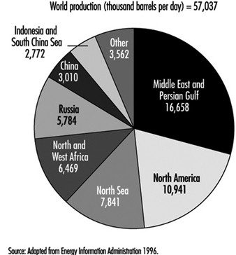
Figure 2. World natural gas plant liquids production - 1995
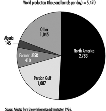
The names of crude oils often identify both the type of crude and areas where they were originally discovered. For example, the first commercial crude oil, Pennsylvania Crude, is named after its place of origin in the United States. Other examples are Saudi Light and Venezuelan Heavy. Two benchmark crudes used to set world crude prices are Texas Light Sweet and North Sea Brent.
Classification of crude oils
Crude oils are complex mixtures containing many different, individual hydrocarbon compounds; they differ in appearance and composition from one oil field to another, and sometimes are even different from wells relatively near one another. Crude oils range in consistency from watery to tar-like solids, and in colour from clear to black. An “average” crude oil contains about 84% carbon; 14% hydrogen; 1 to 3% sulphur; and less than 1% of nitrogen, oxygen, metals and salts. See table 1 and table 2.
Table 1. Typical approximate characteristics and properties and gasoline potential of various typical crude oils.
|
Crude source and name * |
Paraffins |
Aromatics |
Naphthenes |
Sulphur |
API gravity |
Naphthene yield |
Octane number |
|
Nigerian Light |
37 |
9 |
54 |
0.2 |
36 |
28 |
60 |
|
Saudi Light |
63 |
19 |
18 |
2 |
34 |
22 |
40 |
|
Saudi Heavy |
60 |
15 |
25 |
2.1 |
28 |
23 |
35 |
|
Venezuela Heavy |
35 |
12 |
53 |
2.3 |
30 |
2 |
60 |
|
Venezuela Light |
52 |
14 |
34 |
1.5 |
24 |
18 |
50 |
|
USA Midcontinental Sweet |
— |
— |
— |
0.4 |
40 |
— |
— |
|
USA West Texas Sour |
46 |
22 |
32 |
1.9 |
32 |
33 |
55 |
|
North Sea Brent |
50 |
16 |
34 |
0.4 |
37 |
31 |
50 |
* Representative average numbers.
Table 2. Composition of crude oil and natural gas
Hydrocarbons
Paraffins: The paraffinic saturated chain type hydrocarbon (aliphatic) molecules in crude oil have the formula CnH2n+2, and can be either straight chains (normal) or branched chains (isomers) of carbon atoms. The lighter, straight chain paraffin molecules are found in gases and paraffin waxes. The branched chain paraffins are usually found in heavier fractions of crude oil and have higher octane numbers than normal paraffins.
Aromatics: Aromatics are unsaturated ring type hydrocarbon (cyclic) compounds. Naphthalenes are fused double ring aromatic compounds. The most complex aromatics, polynuclears (three or more fused aromatic rings), are found in heavier fractions of crude oil.
Naphthenes: Naphthenes are saturated ring type hydrocarbon groupings, with the formula
CnH2n, arranged in the form of closed rings (cyclic), found in all fractions of crude oil except the very lightest. Single ring naphthenes (mono-cycloparaffins) with 5 and 6 carbon atoms predominate, with two ring naphthenes (dicycloparaffins) found in the heavier ends of naphtha.
Non-hydrocarbons
Sulphur and sulphur compounds: Sulphur is present in natural gas and crude oil as hydrogen sulphide (H2S), as compounds (thiols, mercaptans, sulphides, polysulphides, etc.) or as elemental sulphur. Each gas and crude oil has different amounts and types of sulphur compounds, but as a rule the proportion, stability and complexity of the compounds are greater in heavier crude oil fractions.
Sulphur compounds called mercaptans, which exhibit distinct odours detectable at very low concentrations, are found in gas, petroleum crude oils and distillates. The most common are methyl and ethyl mercaptans. Mercaptans are often added to commercial gas (LNG and LPG) to provide an odour for leak detection.
The potential for exposure to toxic levels of H2S exists when working in drilling, production, transportation and processing crude oil and natural gas. The combustion of petroleum hydrocarbons containing sulphur produces undesirables such as sulphuric acid and sulphur dioxide.
Oxygen compounds: Oxygen compounds, such as phenols, ketones and carboxylic acids, are found in crude oils in varying amounts.
Nitrogen compounds: Nitrogen is found in lighter fractions of crude oil as basic compounds, and more often in heavier fractions of crude oil as non-basic compounds which may also include trace metals.
Trace metals: Trace amounts, or small quantities of metals, including copper, nickel, iron, arsenic and vanadium, are often found in crude oils in small quantities.
Inorganic salts: Crude oils often contain inorganic salts, such as sodium chloride, magnesium chloride and calcium chloride, suspended in the crude or dissolved in entrained water (brine).
Carbon dioxide: Carbon dioxide may result from the decomposition of bicarbonates present in, or added to crude, or from steam used in the distillation process.
Naphthenic acids: Some crude oils contain naphthenic (organic) acids, which may become corrosive at temperatures above 232 °C when the acid value of the crude is above a certain level.
Normally occurring radioactive materials: Normally occurring radioactive materials (NORMs) are often present in crude oil, in the drilling deposits and in the drilling mud, and can present a hazard from low levels of radioactivity.
Relatively simple crude-oil assays are used to classify crude oils as paraffinic, naphthenic, aromatic or mixed, based on the predominant proportion of similar hydrocarbon molecules. Mixed-base crudes have varying amounts of each type of hydrocarbon. One assay method (US Bureau of Mines) is based on distillation, and another method (UOP “K” factor) is based on gravity and boiling points. More comprehensive crude assays are conducted to determine the value of the crude (i.e., its yield and quality of useful products) and processing parameters. Crude oils are usually grouped according to yield structure, with high-octane gasoline being one of the more desirable products. Refinery crude oil feedstocks usually consist of mixtures of two or more different crude oils.
Crude oils are also defined in terms of API (specific) gravity. For example, heavier crude oils have low API gravities (and high specific gravities). A low-API gravity crude oil may have either a high or low flashpoint, depending on its lightest ends (more volatile constituents). Because of the importance of temperature and pressure in the refining process, crude oils are further classified as to viscosity, pour points and boiling ranges. Other physical and chemical characteristics, such as colour and carbon residue content, are also considered. Crude oils with high carbon, low hydrogen and low API gravity are usually rich in aromatics; while those with low carbon, high hydrogen and high API gravity are usually rich in paraffins.
Crude oils which contain appreciable quantities of hydrogen sulphide or other reactive sulphur compounds are called “sour.” Those with less sulphur are called “sweet.” Some exceptions to this rule are West Texas crudes (which are always considered “sour” regardless of their H2S content) and Arabian high-sulphur crudes (which are not considered “sour” because their sulphur compounds are not highly reactive).
Compressed Natural Gas and Liquefied Hydrocarbon Gases
The composition of naturally occurring hydrocarbon gases is similar to crude oils in that they contain a mixture of different hydrocarbon molecules depending on their source. They can be extracted as natural gas (almost free of liquids) from gas fields; petroleum-associated gas which is extracted with oil from gas and oil fields; and gas from gas condensate fields, where some of the liquid components of oil convert into the gaseous state when pressure is high (10 to 70 mPa). When the pressure is decreased (to 4 to 8 mPa) condensate containing heavier hydrocarbons separates from the gas by condensation. Gas is extracted from wells reaching up to 4 miles (6.4 km) or more in depth, with seam pressures varying from 3 mPa up to as high as 70 mPa. (See figure 3.)
Figure 3. Offshore natural gas well set in 87.5 metres of water in the Pitas Point area of the Santa Barbara Channel, Southern California
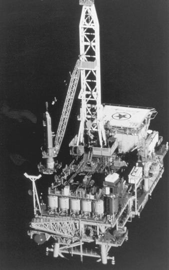
American Petroleum Institute
Natural gas contains 90 to 99% hydrocarbons, which consist predominately of methane (the simplest hydrocarbon) together with smaller amounts of ethane, propane and butane. Natural gas also contains traces of nitrogen, water vapour, carbon dioxide, hydrogen sulphide and occasional inert gases such as argon or helium. Natural gases containing more than 50 g/m3 of hydrocarbons with molecules of three or more carbon atoms (C3 or higher) are classified as “lean” gases.
Depending how it is used as a fuel, natural gas is either compressed or liquefied. Natural gas from gas and gas condensate fields is processed in the field to meet specific transportation criteria before being compressed and fed into gas pipelines. This preparation includes removal of water with driers (dehydrators, separators and heaters), oil removal using coalescing filters, and the removal of solids by filtration. Hydrogen sulphide and carbon dioxide are also removed from natural gas, so that they do not corrode pipelines and transportation and compression equipment. Propane, butane and pentane, present in natural gas, are also removed before transmission so they will not condense and form liquids in the system. (See the section “Natural gas production and processing operations.”)
Natural gas is transported by pipeline from gas fields to liquefication plants, where it is compressed and cooled to approximately –162 ºC to produce liquefied natural gas (LNG) (see figure 4). The composition of LNG is different from natural gas due to the removal of some impurities and components during the liquefaction process. LNG is primarily used to augment natural gas supplies during peak demand periods and to supply gas in remote areas away from major pipelines. It is regasified by adding nitrogen and air to make it comparable to natural gas before being fed into gas supply lines. LNG is also used as a motor-vehicle fuel as an alternative to gasoline.
Figure 4. World’s largest LNG plant at Arzew, Algeria
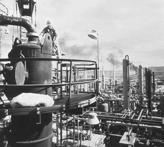
American Petroleum Institute
Petroleum-associated gases and condensate gases are classified as “rich” gases, because they contain significant amounts of ethane, propane, butane and other saturated hydrocarbons. Petroleum-associated and condensate gases are separated and liquefied to produce liquefied petroleum gas (LPG) by compression, adsorption, absorption and cooling at oil and gas process plants. These gas plants also produce natural gasoline and other hydrocarbon fractions.
Unlike natural gas, petroleum-associated gas and condensate gas, oil processing gases (produced as by-products of refinery processing) contain considerable amounts of hydrogen and unsaturated hydrocarbons (ethylene, propylene and so on). The composition of oil processing gases depends upon each specific process and the crude oils used. For example, gases obtained as a result of thermal cracking usually contain significant amounts of olefins, while those obtained from catalytic cracking contain more isobutanes. Pyrolysis gases contain ethylene and hydrogen. The composition of natural gases and typical oil processing gases is shown in table 3.
Table 3. Typical approximate composition of natural and oil processing gases (per cent by volume)
|
Type gas |
H2 |
CH4 |
C2H6 |
C3H4 |
C3H8 |
C3H6 |
C4H10 |
C4H8 |
N2+CO2 |
C5+ |
|
Natural gas |
n/a |
98 |
0.4 |
n/a |
0.15 |
n/a |
0.05 |
n/a |
1.4 |
n/a |
|
Petroleum- |
n/a |
42 |
20 |
n/a |
17 |
n/a |
8 |
n/a |
10 |
3 |
|
Oil processing gases |
|
|
|
|
|
|
|
|
|
|
Combustible natural gas, with a calorific value of 35.7 to 41.9 MJ/m3 (8,500 to 10,000 kcal/m3), is primarily used as a fuel to produce heat in domestic, agricultural, commercial and industrial applications. The natural gas hydrocarbon also is used as feedstock for petrochemical and chemical processes. Synthesis gas (CO + H2) is processed from methane by oxygenation or water vapour conversion, and used to produce ammonia, alcohol and other organic chemicals. Compressed natural gas (CNG) and liquefied natural gas (LNG) are both used as fuel for internal combustion engines. Oil processing liquefied petroleum gases (LPG) have higher calorific values of 93.7 MJ/m3 (propane) (22,400 kcal/m3) and 122.9 MJ/m3 (butane) (29,900 kcal/m3) and are used as fuel in homes, businesses and industry as well as in motor vehicles (NFPA 1991). The unsaturated hydrocarbons (ethylene, propylene and so on) derived from oil processing gases may be converted into high-octane gasoline or used as raw materials in the petrochemical and chemical-processing industries.
Properties of Hydrocarbon Gases
According to the US National Fire Protection Association, flammable (combustible) gases are those which burn in the concentrations of oxygen normally present in air. The burning of flammable gases is similar to that of flammable hydrocarbon liquid vapours, as a specific ignition temperature is needed to initiate the burning reaction and each will burn only within a certain defined range of gas-air mixtures. Flammable liquids have a flashpoint (the temperature (always below the boiling point) at which they emit sufficient vapours for combustion). There is no apparent flashpoint for flammable gases, as they are normally at temperatures above their boiling points, even when liquefied, and are therefore always at temperatures well in excess of their flashpoints.
The US National Fire Protection Association (1976) defines compressed and liquefied gases, as follows:
- “Compressed gases are those which at all normal atmospheric temperatures inside their containers, exist solely in the gaseous state under pressure.”
- “Liquefied gases are those which at normal atmospheric temperatures inside their containers, exist partly in the liquid state and partly in the gaseous state, and are under pressure as long as any liquid remains in the container.”
The major factor which determines the pressure inside the vessel is the temperature of the liquid stored. When exposed to the atmosphere, the liquefied gas very rapidly vaporizes, travelling along the ground or water surface unless dispersed into the air by wind or mechanical air movement. At normal atmospheric temperatures, about one-third of the liquid in the container will vaporize.
Flammable gases are further classified as fuel gas and industrial gas. Fuel gases, including natural gas and liquefied petroleum gases (propane and butane), are burned with air to produce heat in ovens, furnaces, water heaters and boilers. Flammable industrial gases, such as acetylene, are used in processing, welding, cutting and heat treating operations. The differences in properties of liquefied natural gas (LNG) and liquefied petroleum gases (LPG) are shown in table 3.
Searching for Oil and Gas
The search for oil and gas requires a knowledge of geography, geology and geophysics. Crude oil is usually found in certain types of geological structures, such as anticlines, fault traps and salt domes, which lie under various terrains and in a wide range of climates. After selecting an area of interest, many different types of geophysical surveys are conducted and measurements performed in order to obtain a precise evaluation of the subsurface formations, including:
- Magnetometric surveys. Magnetometers hung from airplanes measure variations in the earth’s magnetic field in order to locate sedimentary rock formations which generally have low magnetic properties when compared to other rocks.
- Aerial photogrammetric surveys. Photographs taken with special cameras in airplanes, provide three-dimensional views of the earth which are used to determine land formations with potential oil and gas deposits.
- Gravimetric surveys. Because large masses of dense rock increase the pull of gravity, gravimeters are used to provide information regarding underlying formations by measuring minute differences in gravity.
- Seismic surveys. Seismic studies provide information on the general characteristics of the subsurface structure (see figure 5). Measurements are obtained from shock waves generated by setting off explosive charges in small-diameter holes, from the use of vibrating or percussion devices on both land and in water, and from underwater blasts of compressed air. The elapsed time between the beginning of the shock wave and the return of the echo is used to determine the depth of the reflecting substrata. The recent use of super-computers to generate three-dimensional images greatly improves evaluation of seismic test results.
Figure 5. Saudi Arabia, seismic operations
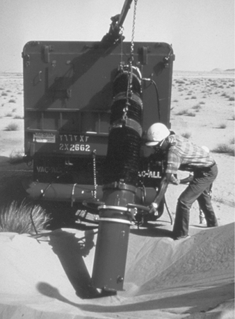
American Petroleum Institute
- Radiographic surveys. Radiography is the use of radio waves to provide information similar to that obtained from seismic surveys.
- Stratigraphic surveys. Stratigraphic sampling is the analysis of cores of subsurface rock strata for traces of gas and oil. A cylindrical length of rock, called a core, is cut by a hollow bit and pushed up into a tube (core barrel) attached to the bit. The core barrel is brought to the surface and the core is removed for analysis.
When the surveys and measurements indicate the presence of formations or strata which may contain petroleum, exploratory wells are drilled to determine whether or not oil or gas is actually present and, if so, whether it is available and obtainable in commercially viable quantities.
Offshore Operations
Although the first offshore oil well was drilled in the early 1900s off of the coast of California, the beginning of modern marine drilling was in 1938, with a discovery in the Gulf of Mexico, 1 mile (1.6 km) from the US coastline. After the Second World War, offshore drilling expanded quickly, first in shallow waters adjacent to known land-based production areas, and then to other shallow and deep water areas around the world, and in climates varying from the Arctic to the Persian Gulf. In the beginning, offshore drilling was possible only in water depths of about 91 m; however, modern platforms are now able drill in waters over 3.2 km deep. Offshore oil activities include exploration, drilling, production, processing, underwater construction, maintenance and repair, and the transport of the oil and gas to shore by ship or pipeline.
Offshore platforms
Drilling platforms support drilling rigs, supplies and equipment for offshore or inland water operations, and range from floating or submergible barges and ships, to fixed-in-place platforms on steel legs used in shallow waters, to large, buoyant, reinforced concrete, gravity-type platforms used in deep waters. After the drilling is completed, marine platforms are used to support production equipment. The very largest production platforms have accommodations for over 250 crew members and other support personnel, heliports, processing plants and crude oil and gas condensate storage capability (see figure 6).
Figure 6. Drilling vessels; drill ship Ben Ocean Laneer

American Petroleum Institute
Typically, with deep water floating platform drilling, the wellhead equipment is lowered to the ocean floor and sealed to the well casing. The use of fibre-optic technology allows a large, central platform to remotely control and operate smaller satellite platforms and sub-sea templates. Production facilities on the large platform process the crude oil, gas and condensate from the satellite facilities, before it is shipped on-shore.
The type of platform used in underwater drilling is often determined by the type of well to be drilled (exploratory or production) and by the depth of the water (see table 4).
Table 4. Platform types for underwater drilling
|
Platform type |
Depth (m) |
Description |
|
Submersible barges and platforms |
15–30 |
Barges or platforms, towed to the site and sunk to rest on the bottom. Lower buoyant column keeps rigs afloat |
|
Jack-ups (on legs) |
30–100 |
Mobile, self-elevating buoyant platforms whose legs are jacked up for towing. At the site, the legs are lowered to |
|
Floating platforms |
100–3,000+ |
Large, self-contained, multi-level, reinforced concrete gravity structures, towed to the site, submerged with |
|
Smaller floating platforms, similarly suspended, which support only the drilling rig and are serviced by a floating |
||
|
Drilling barges |
30–300 |
Self-propelled, floating or semi-submersible barges. |
|
Drill ships |
120–3,500+ |
Highly sophisticated, specially designed, floating or semi-submersible ships. |
|
Fixed on site platforms |
0–250 |
Platforms built on steel supports (jackets) which are sunk and fixed in place, and artificial islands used as |
|
Sub-sea templates |
n/a |
Underwater production installations. |
Types of Wells
Exploratory wells.
Following the analysis of geological data and geophysical surveys, exploratory wells are drilled, either on land or offshore. Exploratory wells which are drilled in areas where neither oil nor gas has been previously found are called “wildcats.” Those wells which strike oil or gas are called “discovery wells.” Other exploratory wells, known as “step-out” or “appraisal” wells, are drilled to determine the limits of a field following discovery, or to search for new oil- and gas-bearing formations next to, or beneath, those already known to contain product. A well which does not find any oil or gas, or finds too little to produce economically, is called a “dry hole”.
Developmental wells.
After a discovery, the area of the reservoir is roughly determined with a series of step-out or appraisal wells. Developmental wells are then drilled to produce gas and oil. The number of developmental wells to be drilled is determined by the expected definition of the new field, both in size and in productivity. Because of the uncertainty as to how reservoirs are shaped or confined, some developmental wells may turn out to be dry holes. Occasionally, drilling and producing occurs simultaneously.
Geopressure/geothermal wells.
Geopressure/geothermal wells are those which produce extremely high-pressure (7,000 psi) and high-temperature (149 ºC) water which may contain hydrocarbons. The water becomes a rapidly expanding cloud of hot steam and vapours upon release to the atmosphere from a leak or rupture.
Stripper wells.
Stripper wells are those which produce less than ten barrels of oil a day from a reservoir.
Multiple completion wells.
When multiple producing formations are discovered when drilling a single well, a separate string of pipe may be run into a single well for each individual formation. Oil and gas from each formation is directed into its respective piping and isolated from one another by packers, which seal the annular spaces between the piping string and the casing. These wells are known as multiple completion wells.
Injection wells.
Injection wells pump air, water, gas or chemicals into reservoirs of producing fields, either to maintain pressure or move oil toward producing wells by hydraulic force or increased pressure.
Service wells.
Service wells include those used for fishing and wire-line operations, packer/plug placement or removal and reworking. Service wells are also drilled for underground disposal of salt water, which is separated from crude oil and gas.
Drilling Methods
Drilling rigs.
Basic drilling rigs contain a derrick (tower), a drilling pipe, a large winch to lower and lift out the drilling pipe, a drilling table which rotates the drilling pipe and bit, a mud mixer and pump and an engine to drive the table and winch (see figure 7). Small drilling rigs used to drill exploratory or seismic wells may be mounted on trucks for movement from site to site. Larger drilling rigs are either erected onsite or have portable, hinged (jack knife) derricks for easy handling and erection.
Figure 7. Drilling rig on Elf Ringnes Island in the Canadian Arctic

American Petroleum Institute
Percussion or cable drilling.
The oldest drilling technique is percussion or cable drilling. This slow, limited depth method, which is seldom used, involves crushing rock by raising and dropping a heavy chisel bit and stem on the end of a cable. At intervals, the bit is removed and the cuttings are suspended in water and removed by flushing or pumping to the surface. As the hole deepens, it is lined with steel casing to prevent cave-in and protect against contamination of groundwater. Considerable work is required to drill even a shallow well, and upon striking oil or gas, there is no way to control the immediate flow of product to the surface.
Rotary drilling.
Rotary drilling is the most common method and is used to drill both exploratory and production wells at depths over 5 miles (7,000 m). Lightweight drills, mounted on trucks, are used to drill low-depth seismic wells on land. Medium and heavy rotary mobile and floating drills are used for drilling exploration and production wells. Rotary drilling equipment is mounted on a drilling platform with a 30- to 40-m-high derrick, and includes a rotary table, engine, mud mixer and injector pump, a wire-line drum hoist or winch, and many sections of pipe, each approximately 27 m long. The rotary table turns a square kelly connected to the drilling pipe. The square kelly has a mud swivel on the top which is connected to blowout preventors. The drill pipe rotates at a speed of from 40 to 250 rpm, turning either a drill which has drag bits with fixed chisel-like cutting edges or a drill whose bit has rolling cutters with hardened teeth.
Rotary percussion drilling.
Rotary percussion drilling is a combination method whereby a rotary drill uses a circulating hydraulic fluid to operate a hammer-like mechanism, thereby creating a series of rapid percussion blows which allow the drill to simultaneously bore and pound into the earth.
Electro and turbo drilling.
Most rotary tables, winches and pumps of heavy drills are usually driven by electric motors or turbines, which allows for increased flexibility in operations and remote-controlled drilling. Electro drill and turbo drill are newer methods which provide more direct power to the drill bit by connecting the drilling motor just above the bit at the bottom of the hole.
Directional drilling.
Directional drilling is a rotary drilling technique which directs the drill string along a curved path as the hole deepens. Directional drilling is used to reach deposits which are inaccessible by vertical drilling. It also reduces costs, as a number of wells can be drilled in different directions from a single platform. Extended-reach drilling allows tapping into undersea reservoirs from the shore. Many of these techniques are possible by using computers to direct automatic drilling machines and flexible pipe (coiled tubing), which is raised and lowered without connecting and disconnecting sections.
Other drilling methods.
Abrasive drilling uses an abrasive material under pressure (instead of using a drill stem and bit) to cut through the substrata. Other drilling methods include explosive drilling and flame piercing.
Abandonment.
When oil and gas reservoirs are no longer productive, the wells are typically plugged with cement to prevent flow or leakage to the surface and to protect the underground strata and water. Equipment is removed and the sites of abandoned wells are cleaned up and returned to normal conditions.
Drilling Operations
Drilling techniques
The drilling platform provides a base for workers to couple and uncouple the sections of drilling pipe which are used to increase the depth of drilling. As the hole deepens, additional lengths of pipe are added and the drilling string is suspended from the derrick. When a drilling bit needs to be changed, the entire drilling string of pipe is pulled out of the hole, and each section is detached and stacked vertically inside the derrick. After the new bit is fitted in place, the process is reversed, and the pipe is returned to the hole to continue drilling.
Care is needed to assure that the drilling string pipe does not split apart and drop into the hole, as it may be difficult and costly to fish out and may even result in the loss of the well. Another potential problem is if drilling tools stick in the hole when drilling stops. For this reason, once drilling begins, it usually continues until the well is completed.
Drilling mud
Drilling mud is a fluid composed of water or oil and clay with chemical additives (e.g., formaldehyde, lime, sodium hydrazide, barite). Caustic soda is often added to control the pH (acidity) of drilling mud and to neutralize potentially hazardous mud additives and completion fluids. Drilling mud is pumped into the well under pressure from the mixing tank on the drilling platform, down the inside of the drilling pipe to the drill bit. It then rises between the outside of the drill pipe and the sides of the hole, returning to the surface, where it is filtered and recirculated.
Drilling mud is used to cool and lubricate the drilling bit, lubricate the pipe and flush the rock cuttings from the drill hole. Drilling mud is also used to control flow from the well by lining the sides of the hole and resisting the pressure of any gas, oil or water which is met by the drill bit. Jets of mud may be applied under pressure at the bottom of the hole to aid in drilling.
Casing and cementation
The casing is a special heavy steel pipe which lines the well hole. It is used to prevent cave-in of the drill hole walls and protect fresh water strata by preventing leakage from the returning flow of mud during drilling operations. The casing also seals off water-permeated sands and high-pressure gas zones. Casing is initially used near the surface and is cemented into place to guide the drill pipe. A cement slurry is pumped down the drilling pipe and forced back up through the gap between the casing and the walls of the well hole. Once the cement sets and the casing is place, drilling continues using a smaller diameter bit.
After the surface casing is placed in the well, blowout preventors (large valves, bags or rams) are attached to the top of the casing, in what is called a stack. Following discovery of oil or gas, casing is set into the bottom of the well to keep dirt, rocks, salt water and other contaminants out of the well hole and to provide a conduit for the crude oil and gas extraction lines.
Completion, Enhanced Recovery and Workover Operations
Completion
Completion describes the process of bringing a well into production after the well has been drilled to the depth where oil or gas is expected to be found. Completion involves a number of operations, including penetration of the casing and cleaning out water and sediment from the pipeline so that flow is unimpeded. Special core bits are used to drill and extract cores up to 50 m long for analysis during the drilling operation to determine when penetration should be performed. The drill pipe and bit are first removed and the final string of casing is cemented into place. A perforating gun, which is a metal tube containing sockets holding either bullets or shaped explosive charges, is then lowered into the well. The charges are discharged by electrical impulse through the casing into reservoir to create openings for the oil and gas to flow into the well and to the surface.
The flow of crude oil and natural gas is controlled by a series of valves, called “Christmas trees”, which are placed at the top of the well head. Monitors and controls are installed to automatically or manually operate surface and subsurface safety valves, in the event of a change in pressure, fire or other hazardous condition. Once the oil and gas are produced they are separated, and water and sediment are removed from the crude oil.
Crude oil and gas production and conservation
Producing oil is basically a matter of displacement by either water or gas. At the time of initial drilling, almost all crude oil is under pressure. This natural pressure decreases as oil and gas is removed from the reservoir, during the three phases of a reservoir’s life.
- During the first phase, flush production, the flow is governed by the natural pressure in the reservoir which comes from dissolved gas in the oil, gas trapped under pressure above the oil and hydraulic pressure from water trapped under the oil.
- Artificial lift, the second phase, involves pumping pressurized gas into the reservoir when the natural pressure is expended.
- Phase three, stripper or marginal production, occurs when wells only produce intermittently.
Originally there was little understanding of the forces which affected oil and gas production. The study of oil and gas reservoir behaviour began at the beginning of the 20th century, when it was discovered that pumping water into a reservoir increased production. At that time, the industry was recovering between 10 and 20% of reservoir capacity, as compared to recent recovery rates of over 60% before wells become unproductive. The concept of control is that a faster rate of production more quickly dissipates the pressure in the reservoir, thereby reducing the total amount of oil which can be eventually recovered. Two measures used to conserve petroleum reservoirs are unitization and well spacing.
- Unitization is the operation of a field as one unit in order to apply secondary recovery methods and maintain pressure, even through a number of different operators may be involved. The total production is allocated on an equitable basis among the operators.
- Well spacing is the limiting and proper location of wells so as to achieve maximum production without dissipating a field due to overdrilling.
Methods of Recovering Additional Product
Productivity of oil and gas reservoirs is improved by a variety of recovery methods. One method is either to chemically or physically open passages in the strata to allow oil and gas to move more freely through reservoirs to the well. Water and gas are injected into reservoirs to maintain working pressure by natural displacement. Secondary recovery methods, including displacement by pressure, artificial lift and flooding, improve and restore reservoir pressure. Enhanced recovery is the use of various secondary recovery methods in multiple and different combinations. Enhanced recovery also includes more advanced methods of obtaining additional product from depleted reservoirs, such as thermal recovery, which uses heat instead of water or gas to force more crude oil out of reservoirs.
Acidizing
Acidizing is a method of increasing the output of a well by pumping acid directly into a producing reservoir to open flow channels through the reaction of chemicals and minerals. Hydrochloric (or regular) acid, was first used to dissolve limestone formations. It is still most commonly used; however, various chemicals are now added to the hydrochloric acid to control its reaction and to prevent corrosion and formation of emulsions.
Hydrofluoric acid, formic acid and acetic acid are also used, together with hydrochloric acid, depending on the type of rock or minerals in the reservoir. Hydrofluoric acid is always combined with one of the other three acids, and was originally used to dissolve sandstone. It is often called “mud acid”, as it is now used to clean perforations which have been plugged with drilling mud and to restore damaged permeability near the well hole. Formic and acetic acids are used in deep, ultra-hot limestone and dolomite reservoirs and as breakdown acids prior to perforation. Acetic acid is also added to wells as a neutralizing buffer agent to control the pH of well stimulation fluids. Almost all acids have additives, such as inhibitors to prevent reaction with the metal casings and surfactants to prevent formation of sludge and emulsions.
Fracturing
Fracturing describes the method used to increase the flow of oil or gas through a reservoir and into wells by force or pressure. Production may decrease because the reservoir formation is not permeable enough to allow the oil to flow freely toward the well. Fracturing forces open underground channels by pumping a fluid treated with special propping agents (including sand, metal, chemical pellets and shells) into the reservoir under high pressure to open fissures. Nitrogen may be added to the fluid to stimulate expansion. When the pressure is released, the fluid withdraws and the propping agents remain in place, holding the fissures open so that oil can flow more freely.
Massive fracturing (mass frac) involves pumping large amounts of fluid into wells to hydraulically create fissures which are thousands of feet in length. Massive fracturing is typically used to open gas wells where the reservoir formations are so dense that even gas cannot pass through them.
Pressure maintenance
Two common pressure maintenance techniques are the injection of water and gas (air, nitrogen, carbon dioxide and natural gas) into reservoirs where natural pressures are reduced or insufficient for production. Both methods require drilling auxiliary injection wells at designated locations to achieve the best results. The injection of water or gas to maintain the working pressure of the well is called natural displacement. The use of pressurized gas to increase the pressure in the reservoir is called artificial (gas) lift.
Water flooding
The most commonly used secondary enhanced recovery method is pumping water into an oil reservoir to push product toward producing wells. In five-spot water flooding, four injection wells are drilled to form a square with the producing well at the center. The injection is controlled to maintain an even advance of the water front through the reservoir toward the producing well. Some of the water used is salt water, obtained from the crude oil. In low-tension water flooding, a surfactant is added to the water to assist the flow of oil through the reservoir by reducing its adhesion to rock.
Miscible flooding
Miscible fluid and miscible polymer flooding are enhanced recovery methods used to improve water injection by reducing the surface tension of crude oil. A fluid miscible (one that can be dissolved in the crude) is injected into a reservoir. This is followed by an injection of another fluid which pushes the crude and miscible fluid mixture toward the producing well. Miscible polymer flooding involves the use of a detergent to wash the crude oil from the strata. A gel or thickened water is injected behind the detergent to move the crude toward the producing well.
Fire flooding
Fire flooding, or in situ (in place) combustion, is an expensive thermal recovery method wherein large quantities of air or oxygen-containing gas is injected into the reservoir and a portion of the crude oil is ignited. The heat from the fire reduces the viscosity of the heavy crude oil so that it flows more easily. Hot gases, produced by the fire, increase the pressure in the reservoir and create a narrow burning front which pushes the thinner crude from the injection well to the producing well. The heavier crude remains in place, providing additional fuel as the flame front moves slowly forward. The burning process is closely monitored and controlled by regulating the injected air or gas.
Steam injection
Steam injection, or steam flooding, is a thermal recovery method which heats heavy crude oil and lowers its viscosity by injecting super-hot steam into the lowest stratum of relatively shallow reservoir. The steam is injected over a period of 10 to 14 days, and the well is shut for another week or so to allow the steam to thoroughly heat the reservoir. At the same time the increased heat expands reservoir gases, thereby increasing the pressure in the reservoir. The well is then reopened and the heated, less viscous crude flows up into the well. A newer method injects low-heat steam at lower pressure into larger sections of two, three or more zones simultaneously, developing a “steam chest” which squeezes down the oil in each of the zones. This provides a greater flow of oil to the surface, while using less steam.
Natural Gas Production and Processing Operations
There are two types of wells producing natural gas. Wet gas wells produce gas which contains dissolved liquids, and dry gas wells produce gas which cannot be easily liquefied
After natural gas is withdrawn from producing wells, it is sent to gas plants for processing. Gas processing requires a knowledge of how temperature and pressure interact and affect the properties of both fluids and gases. Almost all gas-processing plants handle gases that are mixtures of various hydrocarbon molecules. The purpose of gas processing is to separate these gases into components of similar composition by various processes such as absorption, fractionation and cycling, so they can be transported and used by consumers.
Absorption processes
Absorption involves three processing steps: recovery, removal and separation.
Recovery.
Removes undesirable residue gases and some methane by absorption from the natural gas. Absorption takes place in a counterflow vessel, where the well gas enters the bottom of the vessel and flows upward through absorption oil, which is flowing downward. The absorption oil is “lean” as it enters the top of the vessel, and “rich” as it leaves the bottom as it has absorbed the desirable hydrocarbons from the gas. The gas leaving the top of the unit is called “residue gas.”
Absorption may also be accomplished by refrigeration. The residue gas is used to pre-cool the inlet gas, which then passes through a gas chiller unit at temperatures from 0 to –40 ºC. Lean absorber oil is pumped through an oil chiller, before contacting the cool gas in the absorber unit. Most plants use propane as the refrigerant in the cooler units. Glycol is injected directly into the inlet gas stream to mix with any water in the gas in order to prevent freezing and formation of hydrates. The glycol-water mixture is separated from the hydrocarbon vapour and liquid in the glycol separator, and then reconcentrated by evaporating the water in a regenerator unit.
Removal.
The next step in the absorption process is removal, or demethanization. The remaining methane is removed from the rich oil in ethane recovery plants. This is usually a two-phase process, which first rejects at least one-half of the methane from the rich oil by reducing pressure and increasing temperature. The remaining rich oil usually contains enough ethane and propane to make reabsorption desirable. If not sold, the overhead gas is used as plant fuel or as a pre-saturator, or is recycled to the inlet gas in the main absorber.
Separation.
The final step in the absorption process, distillation, uses vapours as a medium to strip the desirable hydrocarbons from the rich absorption oil. Wet stills use steam vapours as the stripping medium. In dry stills, hydrocarbon vapours, obtained from partial vaporization of the hot oil pumped through the still reboiler, are used as the stripping medium. The still controls the final boiling point and molecular weight of the lean oil, and the boiling point of the final hydrocarbon product mix.
Other Processes
Fractionation.
Is the separation of the desirable hydrocarbon mixture from absorption plants, into specific, individual, relatively pure products. Fractionation is possible when the two liquids, called top product and bottom product, have different boiling points. The fractionation process has three parts: a tower to separate products, a reboiler to heat the input and a condenser to remove heat. The tower has an abundance of trays so that a lot of vapour and liquid contact occurs. The reboiler temperature determines the composition of the bottom product.
Sulphur recovery.
Hydrogen sulphide must be removed from gas before it is shipped for sale. This is accomplished in sulphur recovery plants.
Gas cycling.
Gas cycling is neither a means of pressure maintenance nor a secondary method of recovery, but is an enhanced recovery method used to increase production of natural gas liquids from “wet gas” reservoirs. After liquids are removed from the “wet gas” in cycling plants, the remaining “dry gas” is returned to the reservoir through injection wells. As the “dry gas” recirculates through the reservoir it absorbs more liquids. The production, processing and recirculation cycles are repeated until all of the recoverable liquids have been removed from the reservoir and only “dry gas” remains.
Site Development for Producing Oil and Gas Fields
Extensive site development is required to bring a new oil or gas field into production. Site access may be limited or constrained by both climatic and geographic conditions. The requirements include transportation; construction; maintenance, housing and administrative facilities; oil, gas and water separation equipment; crude oil and natural gas transport; water and waste disposal facilities; and many other services, facilities and kinds of equipment. Most of these are not readily available at the site and must be provided by either the drilling or producing company or by outside contractors.
Contractor activities
Contractors are typically used by oil and gas exploration and producing companies to provide some or all of the following supporting services required to drill and develop producing fields:
- Site preparation - brush clearing, road construction, ramps and walkways, bridges, aircraft landing areas, marine harbour, wharfs, docks and landings
- Erection and installation - drilling equipment, power and utilities, tanks and pipeline, housing, maintenance buildings, garages, hangers, service and administration buildings
- Underwater work - installation, inspection, repair and maintenance of underwater equipment and structures
- Maintenance and repair - drilling and production equipment preventive maintenance, vehicles and boats, machinery and buildings
- Contract services - food service; housekeeping; facility and perimeter protection and security; janitorial, recreation and support activity; warehousing and distribution of protective equipment, spare parts and disposable supplies
- Engineering and technical - testing and analyses, computer services, inspections, laboratories, non-destructive analysis, explosives storage and handling, fire protection, permits, environmental, medical and health, industrial hygiene and safety and spill response
- Outside services - telephone, radio and television, sewerage and garbage
- Transportation and material handling equipment - aircraft and helicopter, marine services, heavy-duty construction and materials handling equipment
Utilities
Whether exploration, drilling and producing operations take place on land or offshore, power, light electricity and other support utilities are required, including:
- Power generation - gas, electricity and steam
- Water - fresh water supply, purification and treatment and process water
- Sewerage and drainage - storm water, sanitary treatment and waste (oily) water treatment and disposal
- Communications - telephone, radio and television, computer and satellite communication
- Utilities - light, heat, ventilation and cooling.
Working Conditions, Health and Safety
Work on drilling rigs usually involves a minimum crew of 6 people (primary and secondary drillers, three assistant drillers or helpers (roughnecks) and a cathead person) reporting to a site supervisor or foreman (tool pusher) who is responsible for the drilling progression. The primary and secondary drillers have overall responsibility for drilling operations and supervision of the drilling crew during their respective shifts. Drillers should be familiar with the capabilities and limitations of their crews, as work can progress only as fast as the slowest crew member.
Assistant drillers are stationed on the platform to operate equipment, read instruments and perform routine maintenance and repair work. The cathead person is required to climb up near the top of the derrick when drill pipe is being fed into or drawn out of the well hole and assist in moving the sections of pipe into and out of the stack. During drilling, the cathead person also operates the mud pump and provides general assistance to the drilling crew.
Persons who assemble, place, discharge and retrieve perforating guns should be trained, familiar with the hazards of explosives and qualified to handle explosives, primer cord and blasting caps. Other personnel working in and around oil fields include geologists, engineers, mechanics, drivers, maintenance personnel, electricians, pipeline operators and labourers.
Wells are drilled around the clock, on either 8- or 12-hour shifts, and workers require considerable experience, skill and stamina to meet the rigorous physical and mental demands of the job. Overextending a crew may result in a serious accident or injury. Drilling requires close teamwork and coordination in order to accomplish the tasks in a safe and timely fashion. Because of these and other requirements, consideration must be given to the morale and health and safety of workers. Adequate periods of rest and relaxation, nutritious food and appropriate hygiene and living quarters, including air conditioning in hot, humid climates and heating in cold-weather areas, are essential.
The primary occupational hazards associated with exploration and production operations include illnesses from exposure to geographical and climatic elements, stress from travelling long distances over water or harsh terrain and personal injury. Psychological problems may result from the physical isolation of exploratory sites and their remoteness from base camps and the extended work periods required on offshore drilling platforms and at remote onshore sites. Many other hazards particular to offshore operations, such as underwater diving, are covered elsewhere in this Encyclopaedia.
Offshore work is dangerous at all times, both when on and off the job. Some workers cannot handle the stress of working offshore at a demanding pace, for extended periods of time, under relative confinement and subject to ever changing environmental conditions. The signs of stress in workers include unusual irritability, other signs of mental distress, excessive drinking or smoking and use of drugs. Problems of insomnia, which may be aggravated by high levels of vibration and noise, have been reported by workers on platforms. Fraternization among workers and frequent shore leave may reduce stress. Seasickness and drowning, as well as exposure to severe weather conditions, are other hazards in offshore work.
Illnesses such as respiratory tract diseases result from exposure to harsh climates, infections or parasitic diseases in areas where these are endemic. Although many of these diseases are still in need of epidemiological study in drilling workers, it is known that oil workers have experienced periarthritis of the shoulder and shoulder blade, humeral epicondylitis, arthrosis of the cervical spine and polyneuritis of the upper limbs. The potential for illnesses as a result of exposure to noise and vibration is also present in drilling operations. The severity and frequency of these drilling-related illnesses appears to be proportional to the length of service and exposure to adverse working conditions (Duck 1983; Ghosh 1983; Montillier 1983).
Injuries while working in drilling and production activities may result from many causes, including slips and falls, pipe handling, lifting pipe and equipment, misuse of tools and mishandling explosives. Burns may be caused by steam, fire, acid or mud containing chemicals such as sodium hydroxide. Dermatitis and skin injuries may result from exposure to crude oil and chemicals.
The possibility exists for acute and chronic exposure to a wide variety of unhealthful materials and chemicals which are present in oil and gas drilling and production. Some chemicals and materials which may be present in potentially hazardous amounts are listed in table 2 and include:
- Crude oil, natural gas and hydrogen sulphide gas during drilling and blowouts
- Heavy metals, benzene and other contaminants present in crude
- Asbestos, formaldehyde, hydrochloric acid and other hazardous chemicals and materials
- Normally occurring radioactive materials (NORMs) and equipment with radioactive sources.
Safety
Drilling and production take place in all types of climates and under varying weather conditions, from tropical jungles and deserts to the frozen Arctic, and from dry land to the North Sea. Drilling crews have to work in difficult conditions, subject to noise, vibration, inclement weather, physical hazards and mechanical failures. The platform, rotary table and equipment are usually slippery and vibrate from the engine and drilling operation, requiring workers to make deliberate and careful movements. The hazard exists for slips and falls from heights when climbing the rig and derrick, and there is risk of exposure to crude oil, gas, mud and engine exhaust fumes. The operation of rapidly disconnecting and then reconnecting drill pipe requires training, skill and precision by workers in order to be done safely time after time.
Construction, drilling and production crews working offshore have to contend with the same hazards as crews working on land, and with the additional hazards specific to offshore work. These include the possibility of collapse of the platform at sea and provisions for specialized evacuation procedures and survival equipment in event of an emergency. Another important consideration when working offshore is the requirement for both deep-sea and shallow-water diving to install, maintain and inspect equipment.
Fire and explosion
There is always a risk of blowout when perforating a well, with a gas or vapour cloud release, followed by explosion and fire. Additional potential for fire and explosion exists in gas process operations.
Offshore platform and drilling rig workers should be carefully evaluated after having a thorough physical examination. The selection of offshore crew members with a history or evidence of pulmonary, cardiovascular or neurological diseases, epilepsy, diabetes, psychological disturbances and drug or alcohol addiction requires careful consideration. Because workers will be expected to use respiratory protection equipment and, in particular, those trained and equipped to fight fires, they must be physically and mentally evaluated for capability of carrying out these tasks. The medical examination should include psychological evaluation reflective of the particular job requirements.
Emergency medical services on offshore drilling rigs and production platforms should include provisions for a small dispensary or clinic, staffed by a qualified medical practitioner on board at all times. The type of medical service provided will be determined by the availability, distance and quality of the available onshore services. Evacuation may be by ship or helicopter, or a physician may travel to the platform or provide medical advice by radio to the onboard practitioner, when needed. A medical ship may be stationed where a number of large platforms operate in a small area, such as the North Sea, to be more readily available and quickly provide service to a sick or injured worker.
Persons not actually working on drilling rigs or platforms should also be given pre-employment and periodic medical examinations, particularly if they are employed to work in abnormal climates or under harsh conditions. These examinations should take into consideration the particular physical and psychological demands of the job.
Personal protection
An occupational hygiene monitoring and sampling programme, in conjunction with a medical surveillance programme, should be implemented to evaluate systematically the extent and effect of hazardous exposures to workers. Monitoring for flammable vapours and toxic exposures, such as hydrogen sulphide, should be implemented during exploration, drilling and production operations. Virtually no exposure to H2S should be permitted, especially on offshore platforms. An effective method of controlling exposure is by using properly weighted drilling mud to keep H2S from entering the well and by adding chemicals to the mud to neutralize any entrapped H2S. All workers should be trained to recognize the presence of H2S and take immediate preventive measures to reduce the possibility of toxic exposure and explosions.
Persons engaged in exploration and production activities should have available and use appropriate personal protective equipment including:
- Head protection (hard hats and weather-proof liners)
- Gloves (oil-resistant, non-slip work gloves, fire insulated or thermal where needed)
- Arm protection (long sleeves or oil-proof gauntlets)
- Foot and leg protection (weather-protected, oil-impervious safety boots with steel toes and non-skid soles)
- Eye and face protection (safety glasses, goggles and face shield for acid handling)
- Skin protection from heat and cold (sun screen ointment and cold-weather face masks)
- Climatized and weather-proof clothing (parkas, rain gear)
- Where required, firefighting gear, flame-resistant clothing and acid-resistant aprons or suits.
Control rooms, living quarters and other spaces on large offshore platforms are usually pressurized to prevent the entry of harmful atmospheres, such as hydrogen sulphide gas, which may be released upon penetration or in an emergency. Respiratory protection may be needed in the event pressure fails, and when there is a possibility of exposure to toxic gases (hydrogen sulphide), asphyxiants (nitrogen, carbon dioxide), acids (hydrogen fluoride) or other atmospheric contaminants when working outside of pressurized areas.
When working around geopressure/geothermal wells, insulated gloves and full heat- and steam-protective suits with supplied breathing air should be considered, as contact with hot steam and vapours can cause burns to skin and lungs.
Safety harnesses and lifelines should be used when on catwalks and gangways, especially on offshore platforms and in inclement weather. When climbing rigs and derricks, harnesses and lifelines with an attached counterweight should be used. Personnel baskets, carrying four or five workers wearing personal flotation devices, are often used to transfer crews between boats and offshore platforms or drilling rigs. Another means of transfer is by “swing ropes.” Ropes used to swing from boats to platforms are hung directly above the edge of the boat landings, while those from platforms to boats should hang 3 or 4 feet from the outer edge.
Providing washing facilities for both workers and clothing and following proper hygiene practices are fundamental measures to control dermatitis and other skin diseases. Where needed, emergency eye wash stations and safety showers should be considered.
Safety protection measures
Oil and gas platform safety shutdown systems use various devices and monitors to detect leaks, fires, ruptures and other hazardous conditions, activate alarms and shut down operations in a planned, logical sequence. Where needed due to the nature of the gas or crude, non-destructive testing methods, such as ultrasonic, radiography, magnetic particle, liquid dye penetrant or visual inspections, should be used to determine the extent of corrosion of piping, heater tubes, treaters and vessels used in crude oil, condensate and gas production and processing.
Surface and sub-surface safety shut-in valves protect onshore installations, single wells in shallow water and multi-well offshore deep-water drilling and production platforms, and are automatically (or manually) activated in the event of fire, critical pressure changes, catastrophic failure at the well head or other emergency. They are also used to protect small injection wells and gas lift wells.
Inspection and care of cranes, winches, drums, wire rope and associated appurtenances is an important safety consideration in drilling. Dropping a pipeline string inside a well is a serious incident, which may result in the loss of the well. Injuries, and sometimes fatalities, can occur when personnel are struck by a wire rope which breaks while under tension. Safe operation of the drilling rig is also dependent on a smooth-running, well maintained draw works, with properly adjusted catheads and braking systems. When working on land, keep cranes a safe distance from electric power lines.
Handling of explosives during exploration and drilling operations should be under the control of a specifically qualified person. Some safety precautions to be considered while using a perforating gun include:
- Never strike or drop a loaded gun, or drop piping or other materials on a loaded gun.
- Clear the line of fire and evacuate unnecessary personnel from the drilling rig floor and the floor below as the perforating gun is lowered into and retrieved from the well hole.
- Control work on or around the wellhead while the gun is in the well.
- Restrict use of radios and prohibit arc welding while the gun is attached to the cable to prevent discharge from an inadvertent electric impulse.
Emergency preparedness planning and drills are important to the safety of workers on oil and gas drilling and production rigs and offshore platforms. Each different type of potential emergency (e.g., fire or explosion, flammable or toxic gas release, unusual weather conditions, worker overboard, and the need to abandon a platform) should be evaluated and specific response plans developed. Workers need to be trained in the correct actions to be taken in emergencies, and familiar with the equipment to be used.
Helicopter safety and survival in the event of dropping into water are important considerations for offshore platform operations and emergency preparedness. Pilots and passengers should wear seat-belts and, where required, survival gear during flight. Life vests should be worn at all times, both during flight and when transferring from helicopter to platform or ship. Careful attention to keep bodies and materials beneath the path of the rotor blade is required when entering, leaving or working around a helicopter.
Training of both onshore and offshore workers is essential to a safe operation. Workers should be required to attend regularly scheduled safety meetings, covering both mandatory and other subjects. Statutory regulations have been enacted by government agencies, including the US Occupational Safety and Health Administration, the US Coast Guard for offshore operations, and the equivalents in the United Kingdom, Norway and elsewhere, which regulate the safety and health of exploration and production workers, both onshore and offshore. The International Labour Organization Code of Practice Safety and Health in the Construction of Fixed Offshore Installations in the Petroleum Industry (1982) provides guidance in this area. The American Petroleum Institute has a number of standards and recommended practices covering safety and health related to exploration and production activities.
Fire protection and prevention measures
Fire prevention and protection, especially on offshore drilling rigs and production platforms, is an important element in the safety of the workers and continued operations. Workers should be trained and educated to recognize the fire triangle, as discussed in the Fire chapter, as it applies to flammable and combustible hydrocarbon liquids, gases and vapours and the potential hazards of fires and explosions. An awareness of fire prevention is essential and includes a knowledge of ignition sources such as welding, open flames, high temperatures, electrical energy, static sparks, explosives, oxidizers and incompatible materials.
Both passive and active fire-protection systems are used onshore and offshore.
- Passive systems include fireproofing, layout and spacing, equipment design, electrical classification and drainage.
- Detectors and sensors are installed which activate alarms, and may also activate automatic protection systems, upon detecting heat, flame, smoke, gas or vapours.
- Active fire protection includes fire water systems, fire water supply, pumps, hydrants, hoses and fixed sprinkler systems; dry chemical automatic systems and manual extinguishers; halon and carbon dioxide systems for confined or enclosed areas such as control rooms, computer rooms and laboratories; and foam water systems.
Employees who are expected to fight fires, from small fires in the incipient stages to large fires in enclosed spaces, such as on offshore platforms, must be properly trained and equipped. Workers assigned as fire brigade leaders and incident commanders need leadership capabilities and additional specialized training in advanced firefighting and fire-control techniques.
Environmental Protection
The major sources of air, water and ground pollution in oil and natural gas production are from oil spills or gas leaks on land or sea, hydrogen sulphide present in oil and gas escaping into the atmosphere, hazardous chemicals present in drilling mud contaminating water or land and combustion products of oil well fires. The potential public health effects of inhalation of smoke particulates from large-scale oil field fires has been of great concern since the oil well fires that occurred in Kuwait during the Persian Gulf War in 1991.
Pollution controls typically include:
- API separators and other waste and water treatment facilities
- Spill control, including booms for spills on water
- Spill containment, dikes and drainage to control oil spills and divert oily water to treatment facilities.
Gas dispersion modelling is conducted to ascertain the probable area which would be affected by a cloud of escaping toxic or flammable gas or vapour. Groundwater table studies are conducted to project the maximum extent of water pollution should oil contamination occur.
Workers should be trained and qualified to provide first aid response to mediate spills and leakage. Contractors who specialize in pollution remediation are usually engaged to manage large spill responses and remediation projects.
General Profile
In 1993, the worldwide production of electricity was 12.3 trillion kilowatt hours (United Nations 1995). (A kilowatt hour is the amount of electricity needed to light ten 100-watt bulbs for 1 hour.) One can judge the magnitude of this endeavour by considering data from the United States, which alone produced 25% of the total energy. The US electric utility industry, a mix of public and privately owned entities, generated 3.1 trillion kilowatt hours in 1993, using more than 10,000 generating units (US Department of Energy 1995). The portion of this industry that is owned by private investors employs 430,000 people in electric operations and maintenance, with revenues of US$200 billion annually.
Electricity is generated in plants which utilize fossil fuel (petroleum, natural gas or coal) or use nuclear energy or hydropower. In 1990, for example, 75% of France’s electrical power came from nuclear power stations. In 1993, 62% of the electricity generated worldwide came from fossil fuels, 19% from hydropower, and 18% from nuclear power. Other reusable sources of energy such as wind, solar, geothermal or biomass account for only a small proportion of world electric production. From generating stations, electricity is then transmitted over interconnected networks or grids to local distribution systems and on through to the consumer.
The workforce that makes all of this possible tends to be primarily male and to possess a high degree of technical skill and knowledge of “the system”. The tasks that these workers undertake are quite diverse, having elements in common with the construction, manufacturing, materials handling, transportation and communications industries. The next few articles describe some of these operations in detail. The articles on electric maintenance standards and environmental concerns also highlight major US government regulatory initiatives that affect the electric utility industry.
Hydroelectric Power Generation
Human beings learned to harness the energy of running water many millennia ago. For more than a century, electricity has been generated using water power. Most people associate the use of water power with the damming of rivers, but hydroelectric energy can also be generated by the harnessing of the tides.
Hydroelectric generation operations span a vast terrain and many climates, ranging from the Arctic permafrost to equatorial rainforest. The geographic location of the generating plant will affect the hazardous conditions that may be present, since occupational hazards such as aggressive insects and animals, or even poisonous plants, will vary from location to location.
A hydrogenerating station generally consists of a dam that traps a large quantity of water, a spillway that releases surplus water in controlled fashion and a powerhouse. Dykes and other water containment and control structures may also be part of the hydroelectric power station, although they are not directly involved in generating electricity. The powerhouse contains conducting channels that guide water through turbines that convert the linear flow of the water into a rotating flow. Water will either fall through the blades of the turbine or else flow horizontally through them. The turbine and generator are connected to each other. Thus, rotation of the turbine causes rotation of the rotor of the generator.
The electric power potential from water flow is the product of the mass of the water, the height through which it falls and gravitational acceleration. The mass is a function of the amount of water that is available and its rate of flow. The design of the power station will determine the height of the water. Most designs draw in water from near the top of the dam and then discharge it at the bottom into an existing downstream riverbed. This optimizes height while maintaining reasonable and controllable flow.
In most modern hydroelectric generating stations, the turbogenerators are oriented vertically. These are the familiar structures that protrude above the main floor in these stations. However, almost all of the structure is located below what is visible at main-floor level. This includes the generator pit, and below that the turbine pit and intake and discharge tube. These structures and the water-guiding channels are entered on occasion.
In stations of older vintage, the turbogenerator is oriented horizontally. The shaft from the turbine protrudes from a wall into the powerhouse, where it connects to the generator. The generator resembles a very large, old-style, open-case electric motor. In testimony to the design and quality of construction of this equipment, some turn-of-the-century facilities still are operating. Some present-day stations incorporate updated versions of the designs of the older stations. In such stations, the water channel completely surrounds the turbogenerator and entry is gained through a tubular casing that passes through the water channel.
A magnetic field is maintained in the windings of the rotor in the generator. The power for this field is provided by banks of lead-acid or caustic-filled nickel cadmium batteries. The motion of the rotor and the magnetic field that is present in its windings induce an electromagnetic field in the windings of the stator. The induced electromagnetic field provides the electrical energy which is supplied to the power grid. Electric voltage is the electrical pressure that arises from the flowing water. In order to maintain the electrical pressure—that is, the voltage—at a constant level requires changing the flow of water across the turbine. This will be done as demand or conditions change.
The flow of electricity can lead to electrical arcing, as for example, in the exciter assembly in the rotor. Electrical arcing can generate ozone, which, even at low levels can adversely affect the rubber in fire hose and other materials.
Hydroelectric power generators produce very high currents and high voltages. Conductors from the generators connect to a unit transformer and from this to a power transformer. The power transformer boosts the voltage and reduces the current for transmission over long distances. Low current minimizes energy loss due to heating during transmission. Some systems use sulphur hexafluoride gas in place of conventional oils as an insulator. Electrical arcing can produce breakdown products which can be significantly more hazardous than sulphur hexafluoride.
The electric circuits include breakers that can rapidly and unpredictably cut out the generator from the power grid. Some units utilize a blast of compressed air to break the connection. When such a unit kicks in, it will produce an extremely high level of impulsive noise.
Administration and Station Operations
Most people are familiar with the administration and station operations aspects of hydro generation, which generally create the public profile of the organization. The power plant administration seeks to ensure that the plant provide reliable service. Administration includes office personnel involved in business and technical functions, and management. Station operations personnel include plant managers and supervisors, and process operators.
Hydrogeneration is a process operation but unlike other process operations, such as those in the chemical industry, many hydrogenerating stations have no operating staff. The generating equipment is operated by remote control, sometimes from long distances. Almost all work activity occurs during maintenance, repair, modification and upgrading of plant and equipment. This mode of operation demands effective systems which can transfer control away from energy production to maintenance to prevent unexpected startup.
Hazards and the management structure
Electrical utilities are traditionally managed as “bottom-up” organizations. That is, the organizational structure has traditionally provided a path of upward mobility that begins with entry-level positions and leads to senior management. Relatively few individuals enter the organization laterally. This means that the supervision and the management in a power utility will likely have experienced the same working conditions as the individuals who presently occupy entry-level positions. Such an organizational structure can have implications with respect to potential worker exposure to hazardous agents, especially those which have chronic cumulative effects. For example, consider noise. Employees who currently serve in management positions could themselves have sustained serious hearing loss when they were employed in jobs that had occupational noise exposures. Their hearing loss could go undetected in company audiometric testing programmes, since such programmes generally include only those employees who are currently exposed to high levels of noise at work.
Maintenance of Generating Equipment
Maintenance of generating equipment subdivides into two main types of activity: electrical maintenance and mechanical maintenance. While both types of work may occur simultaneously and side by side, the skills and work needed to perform these are completely different.
Maintenance could necessitate shutting down and dismantling a unit. Water flow at the intake is controlled by headgates. Headgates are steel structures that are lowered into the intake channel to block the flow of water. Blocking the flow permits water to drain from the interior channels. The quiescent water level in the outlet from the turbine (draught tube) is below the level of the scroll case and blades of the turbine runner. This permits access to these structures. The scroll case is a tapered, spiral-shaped structure that directs the flow of water around the turbine runner in a uniform manner. Water passes from the scroll case through guide vanes that direct flow, and movable vanes (wicket gates) that control the volume.
When needed, the generator and turbine can be removed from their normal locations and placed onto the main floor of the powerhouse. Removal may be necessary for repainting or degreasing and repair and replacement of windings, bearings, brakes or hydraulic systems.
Sometimes the blades of the runner, as well as wicket gates, the guide vanes and the water-conducting structures in the scroll case and draught tube, sustain damage from cavitation. Cavitation occurs when the pressure in the water falls below its vapour pressure. When this happens, gas bubbles form and the turbulence that is caused by these bubbles erodes the materials which the water touches. It may be necessary to repair the damaged materials by welding, or by repairing and recoating the steel and concrete surfaces.
Steel structures may also require repair and recoating if they have become corroded.
Hazards
There are a variety of hazards associated with the generation of hydroelectric power. Some of these hazards are shared by all the employees who work in the industry, while others are restricted to those involved in either electrical or mechanical maintenance activities. Most of the hazards which can arise are summarized in table 1 and table 2, which also summarize precautions.
Table 1. Controlling exposures to selected chemical and biological hazards in hydroelectric power generation
|
Exposure |
Where it can be found |
Affected workers |
Approaches to control |
|
Abrasive dusts |
Dust can contain blast material and paint dust. Paint applied prior to 1971 may contain PCBs. |
Mechanical |
-Dust control system |
|
Asbestos |
Asbestos may be present in generator brakes, pipe and electrical insulation, spray-on coatings, asbestos cement and other products; exposure depends on friability and proximity to source. |
Electrical maintenance |
-Adopt current best practices for work involving asbestos- |
|
Battery |
Short circuit across terminals in banks of batteries could cause explosion and fire and exposure to liquid and aerosols of the electrolyte. |
Electrical maintenance |
-Shielding of battery terminals and noninsulated conductors |
|
Coating |
Emissions can include: carbon monoxide, inorganic pigments containing lead and other chromates and decomposition products from paint resins. PCBs may have been used as plasticizers prior to 1971. PCBs can form furans and dioxins, when heated. |
Mechanical |
-Local exhaust ventilation |
|
Chlorine |
Chlorine exposure can occur during connection/disconnection of chlorine cylinders in water and wastewater treatment systems. |
Operators |
-Follow chlorine industry guidelines when working with chlorine cylinders |
|
Degreasing |
Degreasing of electrical equipment requires solvents with specific properties of inflammability, solvation and rapid evaporation without leaving a residue; solvents meeting these characteristics are volatile and can pose inhalation hazards. |
Electrical maintenance |
-Local exhaust ventilation |
|
Diesel |
Emissions primarily include nitrogen dioxide, nitric oxide, carbon monoxide, carbon dioxide, sulphur dioxide and particulates containing polycyclic aromatic hydrocarbons (PAHs) from vehicles or engines operated in the powerhouse. |
All workers |
-Prohibit operation of automobiles and trucks in buildings. |
|
Insect remains |
Some insects breed in the fast waters around the station; following mating, the adults die and the carcasses decay and dry; some individuals develop allergic respiratory
Following draining, insect larvae living in the water channels may attempt to lower their bodies into remaining water by production of thread-like ropes; some individuals may develop allergic respiratory sensitivity to dust resulting from drying out of these materials. |
All workers
|
-Insects that spend part of their lives in fast-running waters lose habitat as a result of construction of a |
|
Oils and lubricants |
Oils and hydraulic fluids coat windings of the rotor and stator; decomposition of hydrocarbons in contact with hot surfaces can produce polycyclic aromatic hydrocarbons (PAHs). Exposure can occur by inhalation and skin contact. Skin contact can cause dermatitis. |
Electrical maintenance |
-Personal protective equipment (depends on circumstances) |
|
Ozone |
Ozone generated by arcing in the rotor and other electrical equipment could pose an exposure problem, depending on proximity to the source. |
All workers |
-Maintain electrical equipment to prevent arcing |
|
Paint fumes |
Paint aerosols contain sprayed paint and diluent; solvent in droplets and vapour can form flammable mixture; resin system can include isocyanates, epoxies, amines, peroxides and other reactive intermediates. |
Bystanders, painters |
-Paint spray booth |
|
Polychlorinated |
PCBs were used in electrical insulating fluids until the early 1970s; original fluids or residuals may still be present in cables, capacitors, transformers or other equipment; exposure can occur by inhalation or skin contact. Fire or extreme heating during service can convert PCBs into furans and dioxins. |
Electrical maintenance |
-Personal protective equipment |
|
Sulphur hexafluoride |
Electrical arc breakdown of sulphur hexafluoride produces gaseous and solid substances of considerably greater toxicity. |
Electrical maintenance |
-Local exhaust ventilation |
|
Welding and brazing |
Cadmium, lead, silver in solder |
Electrical
Mechanical |
-Local exhaust ventilation |
Table 2. Controlling exposures to selected chemical and biological hazards in hydroelectric power generation
|
Exposure |
Where it can be found |
Affected workers |
Approaches to control |
|
Awkward working |
Prolonged work in awkward posture can lead to musculoskeletal injury. |
All workers |
-Equipment designed to reflect ergonomic principles |
|
Confined spaces |
The dam, control structures, control gates, water-conducting channels, generator and turbine machinery contain many pits, sumps, tanks and other enclosed and partially enclosed spaces that can become oxygen deficient, can confine hazardous atmospheres, or can contain other hazardous conditions. |
All workers |
-Air testing devices |
|
Drowning |
Drowning can occur following a fall into fast-moving water in the forebay (intake zone) or tailrace (discharge zone) or other area. Extremely cold water is present in higher latitudes during spring, fall and winter months. |
All workers |
-Personnel containment barriers |
|
Electrocution |
Areas in the station contain energized, unshielded conductors; equipment containing shielded conductors can become live following removal of the shielding. Electrocution risk results from deliberate entry into unauthorized areas or from accidental failure of protection systems. |
All workers |
-Establish practices and procedures to ensure safe conditions of work with electrical equipment. |
|
Electromagnetic |
Generating and other electrical equipment produces DC and 60 Hz (and higher) AC fields; exposure depends on proximity to source and shielding offered by structures. Magnetic fields are especially difficult to attenuate by shielding. Significance of exposure has yet to be established. Radio frequency: Effects on humans not fully established. |
All workers |
-Hazard not established below present limits |
|
Heat |
Generators develop considerable heat; generators and heat exchangers may discharge heated air into the powerhouse; powerhouse structure can absorb and radiate solar energy into the building; heat injury can occur during warmer months, depending on climate and level of exertion. |
Indoor workers |
-Deflecting heated air towards the roof, shielding, engineering controls |
|
Noise |
Steady-state noise from generators and other sources and tasks could exceed regulated limits; air blast breakers produce very high levels of impact noise; these could discharge at any time. |
All workers |
-Apply noise control technology. |
|
Shiftwork |
Shift operations can produce physiological and psychosocial stresses; psychosocial stresses can be especially serious for the small numbers involved in small and isolated communities where these operations tend to be located. |
Operators |
-Adopt work schedules that reflect current knowledge about circadian rhythms. |
|
Vibration, hand-arm |
Vibration produced by powered hand tools and hand-held equipment is transmitted through hand grips. |
Electrical maintenance |
-Utilize tools meeting current standards for hand-arm vibration. |
|
Vibration, whole-body |
Structure-borne vibration originating from the rotational motion of generators and turbulence of water flows is transmitted through floors and walls. |
All workers |
-Monitor and service rotating equipment to minimize vibration. |
|
Visual display units |
Effective use of computerized workstations depends on application of visual and office ergonomic principles. |
Office workers |
-Apply office ergonomic principles to selection and utilization of video displays |
|
Weather-related |
Ultraviolet energy can cause sunburn, skin cancer and cataracts. Cold can cause cold stress and frostbite. |
Outdoor workers |
-Work clothing that protects against cold |
Environmental Effects
Hydroelectric generation of power has been promoted as being environmentally friendly. Of course, it does provide tremendous benefit to society through the provision of energy and the stabilization of the flow of water. But such generation of energy does not come without an environmental cost, which has in recent years received more and more public recognition and attention. For example, it is now known that flooding large areas of the earth and of rock by acidic water leads to the leaching of metals from these materials. Bioaccumulation of mercury has been found in fish that have been caught in the water from such flooded areas.
Flooding also changes the turbulence patterns in the water as well as the level of oxygenation. Both of these can have serious ecological effects. For example, salmon runs have disappeared on dammed rivers. This disappearance has occurred, in part, because the fish either cannot locate or traverse a path to the higher water level. In addition, the water has come to resemble a lake more than a river, and the still water of a lake is not compatible with salmon runs.
Flooding also destroys fish habitat and can destroy the breeding areas for insects, upon which fish and other organisms depend for nourishment. In some cases, flooding has destroyed productive agricultural and forest lands. Flooding of large areas has also raised concern about climatic change and other changes in the ecological balance. The holdback of fresh water that had been destined to flow into a body of salt water has also raised concern about changes in salinity.
More...
Fossil Fuel Power Generation
The operation of coal-fired electrical generating stations involves a series of steps which may expose workers to traumatic injury and hazardous chemical and physical agents. These hazards may be controlled through a combination of good design, knowledgeable workers and job planning. Good design will ensure that all components meet the necessary codes for integrity and safe operation. It will also ensure that equipment layout allows continuing safe operability and maintainability through easy access. Knowledgeable workers will be aware of hazards in the workplace and will be able to create plans to address the hazards they do encounter. These plans will identify hazards and apply appropriate controls, which may involve a combination of de-energization, physical barriers and personal protective equipment. Analysis of accident experience shows that modern power stations have a safety performance comparable to other heavy mechanical industries. Within the power station staff, most lost-time injuries are suffered by the maintenance staff. Injuries frequently involve sprains and strains to soft tissues of the body, with back strain injuries the most common. Industrial diseases associated with chronic exposure to noise and, occasionally, asbestos are also found.
The operation of a modern powerplant may be considered in a series of steps.
Coal Handling
This includes coal receiving (either by rail or water), storage and recovery for fuelling the turbine generator units. Heavy equipment (tractor-scrapers and bulldozers) is used to create compacted storage piles, which is necessary if spontaneous-combustion fires are to be avoided. Further handling is by conveyors to the powerhouse. Coal dust exposure (leading to possible pneumoconiosis) can be controlled by water spraying of the coal pile and the use of closed control cabs fitted with dust filters. Certain tasks associated with high coal dust levels require respirators with high efficiency particulate absorber (HEPA). Noise levels result in most workers in this work area receiving greater than 85 dBA exposure (leading to hearing loss), which should be controlled through use of ear plugs and muffs, and a hearing conservation programme.
Several conventional safety hazards are found in this area of the plant. Working near water requires careful attention to procedures and also the use of life preservers. Driving heavy equipment on uneven storage piles during the night requires large-scale area lighting, while the lifting and pushing hazards from manual clearing of the conveying coal chutes (which are prone to blockage, particularly when winter is severe) is best controlled through removable chute covers, which provide easy access. Operation and maintenance of extended conveyor systems requires guarding of drive and end pulleys, tensioners and other nip points.
Boiler-Turbine Operation
The operation of a high-pressure boiler-turbine combination should involve a rigorous set of controls to ensure safe operation. These controls include the physical integrity of the equipment and the skill, knowledge and experience of the operating staff. The integrity of the high-pressure components is ensured through a combination of appropriate specifications contained in modern engineering standards, and routine inspections of welded joints using visual and non-destructive imaging techniques (x rays and fluoroscopic methods). In addition, pressure-relief valves, which are regularly tested, ensure that over-pressurizing of the boiler does not occur. The necessary skills and knowledge of the staff may be created through an in-house process of personnel development coupled with government accreditation which extends over several years.
The environment of the powerhouse is a collection of complex engineered systems to carry fuel, combustion air, demineralized boiler water, and cooling water to the boiler. In addition to the high-pressure steam hazards, it contains a variety of other conventional and chemical/physical hazards which must be recognized and controlled. In operation, the most pervasive hazard is noise. Surveys show that all operating and maintenance staff have a time-weighted average exposure of over 85 dBA, which requires the wearing of hearing protection (plugs or muffs) in much of the powerhouse and regular audiometric testing to ensure no deterioration in hearing. Major sources of noise include the coal pulverizers, the turbine-generator unit, and station service air compressors. Dust levels in the powerhouse during operation depend on maintenance attention to the condition of thermal insulation. This is of particular concern as much older insulation contains high levels of asbestos. Careful attention to controls (primarily bonding and containment of damaged insulation) can achieve airborne asbestos concentrations which are undetectable (<0.01 fibre/cc).
The final stage of the operation process which creates potential hazards is ash collection and handling. Usually located outside the powerhouse, ash collection is typically done with large electrostatic precipitators, although there is increasing use of fabric filters in recent years. In both cases the ash is extracted from the flue gas and retained in storage silos. Any subsequent handling processes are inherently dusty despite engineered efforts to control levels. This type of ash (fly ash, as opposed to the bottom ash that has accumulated at the bottom of the boiler) contains a significant fraction (30 to 50%) of respirable material and is therefore a potential concern for possible health effects to exposed workers. Two components of the ash are of potential significance: crystalline silica, associated with silicosis and possibly subsequent lung cancer, and arsenic, associated with skin and lung cancer. In both cases it is necessary to carry out exposure assessments to determine if regulated limits are exceeded and whether specific control programmes are required. These assessments, involving surveys with personal samplers, should include all potentially affected workers, including those who may be exposed during inspections of the dust collection systems and of the grinding and heating surfaces in the boiler, where arsenic is known to deposit. Control programmes, if necessary, should include providing information to the workers about the importance of avoiding ingestion of ash (no eating, drinking or smoking in ash-handling areas), and the need for careful washing after coming in contact with ash. Dust levels encountered in these surveys are usually such that good safety practice indicates a respiratory control programme for exposure to total nuisance dust. The industrial mortality database maintained by the US National Institute for Occupational Safety and Health, for example, contains no entries for deaths attributable to silica or arsenic exposure in the US electrical utility industry.
Maintenance
It is during the maintenance phase that the highest exposure occurs to conventional and chemical/physical agents. Given the complexity of the modern generating station, it is critically important that there be an effective process for isolating equipment so that it cannot be energized while repairs are being carried out. This is typically achieved through a controlled system of locks and tags.
A broad range of conventional hazards are encountered during maintenance. They involve:
- working at heights (fall protection )
- heat stress
- rigging and craning (load security)
- work in confined spaces (atmospheric and conventional hazards)
- excavating (trench collapse)
- working/lifting in cramped environments (sprains and strains).
In all cases, the hazards may be managed by a stepwise process of analysis which identifies hazards and corresponding controls.
A large variety of hazardous commercial products are used and encountered in routine maintenance activities. Asbestos is common, as it has been used widely as thermal insulation and is a component of many commercial products. Control processes should be in place to ensure that all asbestos-containing material is correctly identified by microscopic analysis (on-site capability greatly improves response time). The actual control methods used for the task depend on the scale of the activity. For large-scale jobs, this will involve constructing enclosures that operate under slightly reduced pressure (to prevent leaks) and ensuring that workers are equipped with respiratory protection following careful procedures to avoid external contamination. In all cases the asbestos-containing material should be completely wetted, and bagged and labelled for disposal. Careful examination is necessary to ensure that all asbestos is removed before proceeding. Workers’ exposures should be recorded and periodic chest x rays coupled with pulmonary function testing will determine the onset of any disease. Positive results of these examinations should result in the worker being immediately removed form further exposures. Current practices reflect a high level of concern for asbestos exposures in the electrical utility industry.
For the great majority of other hazardous materials used in the workplace, the quantities involved are small, and the use infrequent, so that the overall impact is insignificant. The most significant class of exposures to hazardous materials are those associated with particular operations rather than particular products.
For example, welding is a common activity that can give rise to a series of possible adverse health outcomes. Exposure to ultraviolet light from the arc causes temporary blindness and severe eye irritation (“arc eye”); inhaled metal oxide fumes may cause “metal fume fever”; and nitrogen oxides and ozone formed at the high temperatures in the arc may cause chemical pneumonia and possible chronic respiratory problems. The controls to be applied include eye shields to protect nearby workers from scattered light, local exhaust ventilation or respiratory protection (through an air-purifying respirator).
A similar common activity is grinding and abrasive blasting, where the concern is for inhalation of the respirable metal oxide and abrasive particles. In this case, the control is usually through choice of abrasive agent (sand has now been abandoned in favour of more benign agents such as vegetable husks) coupled with appropriately high local exhaust ventilation.
The other activity leading to significant exposures is the application of protective coatings to metal surfaces. The coatings may contain a variety of solvents which are released into the working atmosphere. Worker exposures can be controlled either by local exhaust ventilation or, if that is impractical, by respiratory protection.
Nuclear Power Generation
In all nuclear reactors, energy is produced within the fuel by a chain reaction of fissions of the nuclei of its atoms. The most common nuclear fuel is uranium-235. Each fission splits a fuel atom into two new fission product atoms and also expels from its nucleus neutrons which cause further fissions of the atoms. Most of the energy released by the fission is carried away by the fission products, and in turn is converted into thermal energy in the adjacent fuel atoms as they stop these rapidly moving fission products and absorb their radiation. The neutrons carry away about 3% of the energy of fission.
The reactor core is prevented from getting too hot by a liquid or gaseous coolant, which also produces the steam (either directly or indirectly) to drive the turbine. Neutron-absorbing materials are incorporated into control rods, which can be moved in and out of cavities in the core of the reactor to control the fission reaction rate to that desired by the power station operator. In pressurized water reactors, absorbing materials can be put in the reactor coolant system via soluble absorbers.
Most fission products are unstable, and thus radioactive. They decay, releasing radiation of a type and at a rate characteristic of each fission product element, and a new daughter product which may also be radioactive. This decay sequence continues until it finally results in daughter products which are stable (not radioactive). Other radioactive products are formed in the reactor by absorption of neutrons in the nucleus of the atoms of non-fissile materials, such as uranium-238, and structural materials, such as guides, supports and fuel cladding.
In reactors which have been operating for some time, the decay of the fission products and the creation of new fission products reaches a near equilibrium. At this point, the radiation and resulting energy production from the decay of radioactive products is nearly a tenth of all that produced in the reactor.
It is this large amount of radioactive material that creates the risks which are specific to nuclear power stations. Under operating conditions, most of these radioactive materials behave like solids, but some behave like gases, or become volatile at the high temperature in the reactor. Some of these radioactive materials could be readily absorbed into living organisms, and have significant effects on biological processes. Thus, they are dangerous if released or dispersed into the environment.
Nuclear Station Types and Characteristics
Thermal reactors use materials called moderators to slow the fast neutrons produced by fission so that they can be captured more readily by the fissile uranium-235 atoms. Ordinary water is often used as a moderator. Other moderators used are graphite and deuterium, an isotope of hydrogen, which is used in the form of deuterium oxide—heavy water. Ordinary water is mostly hydrogen oxide, and contains a small proportion (0.015%) of heavy water.
Heat is removed from the fuel by a coolant, which directly or indirectly produces steam to drive the turbine, and which also controls the temperature of the reactor core, preventing it from getting too hot and damaging the fuel or structural materials. Coolants in common use in thermal reactors include ordinary water, heavy water and carbon dioxide. Water has good heat transfer characteristics (high specific heat, low viscosity, easily pumped) and is the most common coolant used in nuclear power stations. Cooling a reactor core with pressurized or boiling water allows high core power densities so that large power units can be built into relatively small reactor vessels. However, the reactor coolant system using water must operate at high pressure in order to reach useful steam pressures and temperatures for efficient operation of the steam turbine-generator. The integrity of the reactor cooling system boundary is therefore very important for all water-cooled nuclear power stations, as it is a barrier that protects the safety of the workers, the public and the environment.
The fuel in all water-cooled power reactors, and most other reactors, is ceramic uranium dioxide, clad in metal—stainless steel or a zirconium alloy. The sintered uranium dioxide provides a non-combustible fuel which can operate for extended periods and retain its fission products at high temperatures without significant distortion or failure. The only operating thermal power reactors using other than uranium dioxide fuel, are the Magnox stations (which are carbon dioxide-cooled), and these are gradually being taken out of service as they reach the end of their service life.
Neutron-absorbing materials (such as boron, cadmium, hafnium and gadolinium) used in various forms, such as in steel-clad control rods or in solution in coolants or moderators, can be moved in and out of the reactor core in order to control the fission reaction rate at any designated level. In contrast to fossil fuel power generation, no increase in the quantity of fuel is needed to increase the power level produced in a fission chain reaction.
Once an increase in rate of fission energy production is initiated, it will continue until it is stopped by the insertion into the core of the appropriate quantity of neutron-absorbing materials and moderator. Such a power increase is caused by a surplus of neutrons in the fission chain reaction over that required for just a break-even chain reaction. Therefore, the fission rate and resulting power production can be controlled very sensitively by adding or removing very small amounts of neutron-absorbing materials. If a sudden reduction in power level is required, a relatively large amount of neutron-absorbing material is injected into the core. Each reactor concept has its own reactivity characteristic which determines the designs of control and shutdown neutron-absorbing devices to ensure efficient power control and safe and rapid shutdown when required. However, the same basic control and safety principles apply to all.
The main types of thermal power reactors in service today are illustrated in figure 1, and the main characteristics are given in table 1. In the simplified illustrations in figure 1, concrete shields are shown surrounding the reactors and the primary coolant systems. The shields, which comprise a variety of designs, generally provide both shielding against direct radiation from the reactor and also provide containment of any leaks from reactor cooling or moderator systems, and generally are designed to withstand the significant pressures which could result in the event of a major failure of coolant systems.
Figure 1. Types of nuclear power stations
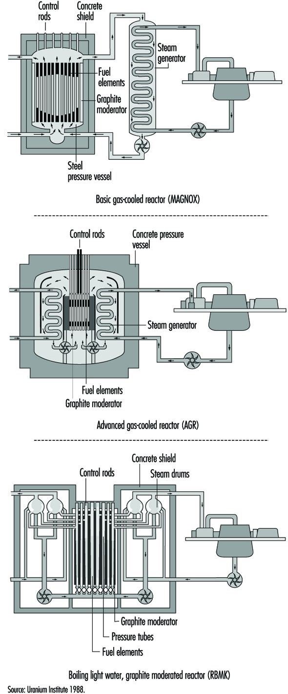
Table 1. Nuclear power station characteristics (1997)
|
Reactor type |
Fuel |
Moderator |
Coolant and its approx. pressure |
Steam generation |
No. of |
Net output |
|
PWR |
Enriched uranium dioxide |
Light water |
Light water |
Indirect |
251 |
223,717 |
|
PHWR (CANDU type) |
Unenriched uranium dioxide |
Heavy water |
Heavy water |
Indirect |
34 |
18,927 |
|
BWR |
Enriched uranium dioxide |
Light water |
Light water |
Direct |
93 |
78,549 |
|
GCR (MAGNOX type) |
Unenriched uranium metal |
Graphite |
Carbon dioxide |
Indirect |
21 |
3,519 |
|
AGR |
Enriched uranium dioxide |
Graphite |
Carbon dioxide |
Indirect |
14 |
8,448 |
|
LWGR (RBMK type) |
Enriched uranium dioxide |
Graphite |
Light water |
Direct |
18 |
13,644 |
|
FBR |
Mixed oxide plutonium |
None |
Sodium |
Indirect |
3 |
928 |
In a pressurized water reactor (PWR) power station, the reactor primary coolant and moderator are the same—purified ordinary water, which is separated from the secondary feedwater/steam circuit by a metallic boundary in steam generators (sometimes called boilers), through which the heat is transferred by conduction. The steam fed to the turbine-generator is therefore not radioactive, and the steam turbine-generator plant can be operated like a conventional power plant. Because hydrogen in the primary coolant/moderator water absorbs a significant fraction of the neutrons, it is necessary to enrich the fuel’s fissile uranium-235 isotope content to between 2% and 5% to sustain a practical chain reaction for long-term power production.
In all operating nuclear power stations with pressurized heavy water reactors (PHWRs), the reactor moderator and primary coolant is heavy water with a very high isotopic deuterium content (>99%). In the CANDU PHWR, which constitutes almost all the operating PHWRs, the moderator is separated from the primary coolant and held at relatively low temperature and pressure, which provides a convenient environment to locate monitoring and control instrumentation, and a built-in back-up cooling capability in the event of primary coolant piping failure. The fuel and primary coolant in the CANDU are in horizontal pressure tubes in the reactor core. As in the PWRs, the primary coolant and secondary feedwater/steam circuit are separated by a metallic boundary in steam generators, through which the heat is transferred from the primary heavy water to the ordinary water steam-feedwater system. The steam fed to the turbine generator plant is therefore ordinary water steam, not radioactive (except for small amounts due to leaks), and the turbine-generator plant can be operated like a conventional thermal power plant. The heavy water moderator and coolant absorbs only a very small fraction of the neutrons generated during fission, allowing a practical chain reaction for long-term power production using natural uranium (0.071% uranium-235). Existing PHWRs can operate with slightly enriched uranium-235 fuel, which results in proportionately greater total energy extraction from the fuel.
In a boiling water reactor (BWR) nuclear power station, the primary cooling water is partially evaporated in the reactor core itself, and the steam generated there is fed directly to the turbine-generator. The operating pressure in the reactor is lower than that in the PWRs, but the steam pressure fed to the turbine is similar. The steam fed to the turbine is slightly radioactive, requiring some precautions because of the potential low-level contamination of the turbine/feedwater system. However, this has not proven to be an important factor in operation and maintenance of BWRs. In BWRs the control of reactor power is affected by the amount of steam in the core, and this has to be offset by appropriate control of the rate of coolant flow or reactivity insertions as the power level of the reactor is changed.
Magnox reactors, also known as gas cooled reactors (GLRs), are fuelled with natural uranium metal clad in magnesium. They are cooled by carbon dioxide at modest pressure, but generate relatively high-temperature steam, which gives good thermal efficiency. They have large cores with low power densities, so that the pressure vessels, which also act as the only containment structures, are also large. The pressure vessels in the early Magnox reactors were steel. In the later Magnox reactors a prestressed concrete vessel contained both the reactor core and the steam-raising heat exchangers.
Advanced gas-cooled reactors (AGRs) use enriched uranium oxide fuel (2.3% U-235). They are cooled by carbon dioxide at higher pressure than the Magnox reactors, and have improved heat transfer and thermal efficiency. The greater core power density in the AGRs compared to the Magnox reactors allows the AGR reactor to be smaller and more powerful. The prestressed concrete pressure vessel, which contains both the reactor core and the steam raising heat exchangers, also acts as the containment structure.
Light water graphite reactors (LWGRs) are a hybrid of different nuclear power systems. The only power stations of this type in operation today are the RBMK reactors located in the former Soviet Union, that is, in Russia, Ukraine and Lithuania. In the RBMK reactors the ordinary water coolant flows upward through vertical coolant channels (tubes) which contain the fuel, and boils within the core. The steam produced in the core is fed directly to the turbine-generator as in a BWR. The graphite moderator which surrounds the coolant channels operates at a temperature sufficiently above that of the coolant so that the heat generated in the graphite by moderating the neutrons is removed by the coolant channels. The RBMK reactors are large and have many coolant channels (>1,500).
Fast breeder reactors (FBRs) require enrichment of fissile material in the range of 20% and can sustain the fission chain reaction primarily by absorbing the fast neutrons produced in the fission process. These reactors do not need a moderator to slow down the neutrons, and can use excess neutrons to breed plutonium-239, a potential fuel for reactors. They can produce more fuel than they consume. While a number of these reactors were built to produce electricity in nine countries around the world, technical and practical difficulties related to the use of liquid metal coolants (sodium) and the very high heat rates has caused interest to wane. There are now only three or four relatively small liquid metal fast breeder reactors (LMFBRs) in service as power producers in the world, producing a total of less than 1,000 megawatts of electric power (MWe), and they are being phased out of service gradually. The technology of breeding reactors, however, has been considerably developed and documented for future use if ever required.
Fuel and Fuel Handling
The process that begins with mining uranium-bearing ore and ends with the final disposal of the used fuel and all fuel processing wastes is usually called the nuclear fuel cycle. There are many variations in fuel cycles, depending on the type of reactor involved and the design of the heat removal arrangements in the reactor core.
The basic PWR and BWR fuel cycles are nearly identical, varying only in the levels of enrichment and the detailed design of the fuel elements. The steps involved, usually at different locations and facilities, are:
- uranium mining and milling to produce yellowcake (U3O8)
- uranium conversion to uranium hexafluoride (UF6)
- enrichment
- fuel fabrication, which involves uranium conversion to uranium dioxide (UO2), fuelled pellet production, fuel rod manufacture in lengths equal to the reactor core height, and manufacture of fuel assemblies containing about 200 fuel rods per assembly in a square array
- installation and operation in a nuclear power plant
- either reprocessing or temporary storage
- shipment of used fuel or enrichment waste to a federal/central repository
- eventual disposal, which is still in the development stage.
Precautions are required during these processes to ensure that the amount of enriched fuel at any location is less than that which could result in a significant fission chain reaction, except, of course, in the reactor. This results in material space restrictions in manufacture, shipping and storage.
In contrast, the CANDU reactor uses natural uranium, and has a simple fuel cycle from mining the ore to fuel disposal, which does not include the steps involved to provide enrichment and reprocessing. The fuel for the CANDU is manufactured semi-automatically in half-metre long round bundles of 28 or 37 fuel rods containing UO2 pellets. There are no space restrictions in manufacturing natural uranium fuel, or in shipping or storing either the new or used fuel. The immobilization and disposal of used CANDU fuel has been under development for 17 years in Canada, and is currently in the concept approval stage.
In all operating power reactors, with the exception of the Magnox type, the basic component of the reactor fuel is the cylindrical fuel pellet, composed of uranium dioxide (UO2) powder which is compacted and then sintered to attain the required density and ceramic characteristics. These sintered pellets, which are sealed in seamless zirconium alloy or stainless steel tubing to produce fuel rods or elements, are chemically inert with respect to their cladding at normal reactor temperatures and pressures. Even if the cladding is damaged or breached and the coolant comes in contact with the UO2, this ceramic material retains most of the radioactive fission products and resists deterioration caused by the high-temperature water.
The Magnox reactors use natural uranium metal fuel clad in magnesium, and operate successfully at relatively high temperatures, because the coolant, carbon dioxide, does not react with these metals under dry conditions.
The basic objective of the design of the fuel rods in a nuclear reactor is to transfer the fission heat generated in the fuel to the coolant, while maintaining the integrity of the fuel rods even under the most severe transient conditions. For all operating reactors, extensive testing of simulated fuel in heat transfer laboratories has demonstrated that the anticipated maximum in-reactor heat transient condition can be accommodated with adequate safety margins by the specific fuel designed and licensed for the application.
New fuel delivered from the fabrication plant to the power station is not significantly radioactive, and can be handled manually or by manually operated lifting/handling tools, without shielding. A typical fuel assembly for a PWR or BWR reactor is a square array of about 200 fuel rods, about 4 m long, weighing about 450 kg. About 200 of these assemblies are required in a large PWR or BWR reactor. The fuel is handled by overhead crane and placed in vertical racks in the dry in the new fuel storage area. To install new fuel in an in-service light-water reactor such as a PWR or BWR, all operations are conducted under a sufficient depth of water to provide shielding for anyone above the reactor. The flanged lid of the reactor vessel must first be removed and some of the used fuel taken out, (usually one-third to one-half reactor core), by overhead crane and fuel-handling elevators.
The used fuel is placed in water-filled storage bays. Other used fuel assemblies in the core may be rearranged in position (generally moved toward the centre of the core), to shape the power production in the reactor. New fuel assemblies are then installed in all vacant fuel site positions. It may require from 2 to 6 weeks to refuel a larger reactor, depending on the workforce and the amount of fuel to be replaced.
The CANDU reactor and some gas-cooled reactors are fuelled on-power by remote-operated equipment which removes used fuel and installs new fuel elements or bundles. In the case of the CANDU, the fuel is half-metre-long bundles of fuel rods, approximately 10 cm in diameter and weighing about 24 kg. The fuel is received from the manufacturer in cardboard packing cases and stored in a designated new-fuel storage area, ready to load into the reactor. Fuel is generally loaded into an operating reactor on a daily basis to sustain the reactivity of the reactor. In a large CANDU reactor, 12 bundles per day is a typical refuelling rate. The bundles are loaded by hand onto a new-fuel loading device which in turn loads the bundles into a fueling machine which is controlled remotely from the station control room. To load new fuel into a reactor, two remote-operated fuelling machines are manoeuvred by remote control and coupled onto the ends of the horizontal fuel channel to be refuelled. The channel is opened by the fuelling machines at both ends while the cooling system is at operating pressure and temperature, and new fuel is pushed in one end and used fuel is withdrawn from the other end of the channel. When the required number of fuel bundles have been installed, the channel seals are re-installed by the fuelling machine, and the fuelling machines may go on to refuel another channel or to discharge the used fuel into the used-fuel water-filled storage bay.
The used fuel discharged from all operating reactors is very radioactive and requires cooling to prevent overheating, and shielding to prevent direct irradiation of any sensitive living organisms or equipment nearby. The usual procedure is to discharge the used fuel into a water-storage pool with at least 4 m of water coverage over the fuel for shielding. This allows safe observation of the fuel through the water, and access for moving it under water to a more long-term storage location.
One year after discharge from a reactor, the overall radioactivity and heat generation from used fuel will decrease to about 1% of its initial value on discharge, and within 10 years to about 0.1% of its initial value at discharge. After about 5 to 10 years from discharge, the heat production has decreased to the point that it is feasible to remove the fuel from the water pool and store it in the dry form in a container with only natural circulation of air around the fuel container. However, it is still quite radioactive, and shielding of its direct radiation is required for many decades. Prevention of ingestion of the fuel material by living organisms is required for a much longer period.
The actual disposal of used fuel from power reactors is still in the development and approval stages. Disposal of used fuel from power reactors in various geologic structures is being studied intensely in a number of countries, but has not as yet been approved anywhere in the world. The concept of storage deep underground in stable rock structures is now in the approval process in Canada as a safe and practical method of finally disposing of these high-level radioactive wastes. However, it is anticipated that even with concept approval by the year 2000, the actual disposal of used fuel will not take place until about 2025.
In-plant Operations
In all 33 countries with nuclear power programmes, there are regulatory bodies that establish and enforce safety regulations related to the operation of nuclear facilities. However, it is generally the power utility which owns and operates nuclear power facilities that is held responsible and liable for the safe operation of its nuclear power plants. The role of the operator is really a management task of information gathering, planning and decision making, and only occasionally includes a more active control when routine operation is disrupted. The operator is not the primary protective system.
All modern nuclear power plants have highly reliable automatic, very responsive control and safety systems which protect the reactor and other plant components continuously, and which are generally designed to be fail-safe on loss of power. The operator is not expected to duplicate or substitute for these automatic control and protective systems. The operator, however, must be able to shut down the reactor almost instantly if necessary, and should be capable of recognizing and responding to any aspect of plant operation, thus adding to the diversity of protection. The operator needs the ability to understand, diagnose and anticipate the development of the overall situation from a large amount of data provided by the automatic data and information systems.
The operator is expected to:
- understand what the normal conditions are in all systems relevant to the current overall status of the plant
- recognize, with help from the automatic systems or special monitoring devices, when abnormal conditions arise, and their significance
- know how to respond correctly to restore the plant to normal operation, or bring the plant to a safe shutdown condition.
How well the operator can do this depends on the design of the machine as well as the operator’s ability and training.
Every nuclear power station must have competent, stable and well-trained operators on duty at all times. Potential nuclear operators undergo a comprehensive training programme, which usually includes classroom and on-the-job training in science, equipment and power systems, radiation protection and operating policies and principles. Training simulators are always used in US utility nuclear plant operation to provide the operator with hands-on experience in plant operations, during upsets and in unusual conditions. The interface between the operator and the power systems is through the control room instrumentation. Well-designed instrumentation systems can improve the understanding and proper response of the operators.
It is usual to appoint the key operating staff for a nuclear power station while it is still under construction, so they can advise from an operating point of view, and can assemble staff who will commission and operate the station. They also prepare a comprehensive set of operating procedures before the station is commissioned and allowed to operate. Design experts and regulatory personnel inspect these procedures for consistency of design intent and operating practices.
The staff are expected to operate the station systematically and rigorously in accordance with the operating procedures and work authorizations. The operating staff continually work to ensure public safety by conducting a comprehensive programme of testing and monitoring the safety systems and protective barriers, and by maintaining the ability to deal with any plant emergency. Where operators may have to take action in response to an alteration in the state of the plant, there are written, systematic procedures to guide them and to provide the detailed information needed to control the plant. Such procedures are reviewed by station and regulatory safety committees.
A well-thought-out operation safety management programme includes:
- detailed knowledge of areas critical to safety
- standards or targets that define acceptable performance
- a programme for monitoring performance, responding to problems and reporting results
- an experience review programme to establish trends, the degree of compliance with standards and the cause of any unacceptable or deteriorating performance
- a means of assessing the impact of proposed changes to hardware or operating procedures and implementing changes consistent with the accepted standard.
In addition to procedures for normal operation, there is an event-reporting system at each nuclear power station to investigate and document any failures and deterioration of equipment, shortcomings in design or construction, and operating errors detected by monitoring systems or regular tests and inspections. The basic cause of each event is determined so that the appropriate corrective or preventive action can be developed. Event reports, including the results of the analysis and recommendations, are reviewed by the station management and by experts in safety and human factors, who are usually based off the station site.
The International Atomic Energy Agency’s (IAEA) Incident Reporting System operates around the world to complement the national systems and ensure that information is shared among all participating countries. The World Association of Nuclear Operators (WANO) also provides a detailed information exchange at the operational level.
Nuclear reactors and all their auxiliary and safety-related systems are maintained and tested according to quality assurance requirements at planned intervals, to ensure reliability throughout their service life. In addition to automatic monitoring, there are systematic manual tests and investigations for evidence of impairment or failure of equipment systems. These include regular field surveillance, preventive maintenance, periodic tests and the study of changes in plant conditions.
Very demanding performance targets are set for process and safety systems to keep the risk to the public and station staff acceptably small. For process systems, which are actively operating while electricity is being generated, failure rates are compared to performance targets, which may result in design changes where performance is substandard. Safety systems need a different approach, because they come into operation only if process systems fail. Comprehensive test programmes monitor these systems and their components, and the results are used to determine how much of the time each of them would likely be out of service. The total amount of time the safety systems are calculated to be out of service is compared to a very high performance standard. If a deficiency is detected in a safety system it is put right immediately or the reactor is shut down.
There are also extensive tests and maintenance programmes during periodic scheduled shutdowns. For example, all pressure-bearing vessels, components and their welds are systematically inspected by non-destructive methods according to safety code regulations.
Safety Principles and Related Safety Design Features
There are four aspects of the fission chain reaction which could be dangerous and which cannot be separated from the use of nuclear energy to produce electricity, and therefore require safety measures:
- Fission results in ionizing radiation, which requires shielding from direct exposure to radiation.
- Highly radioactive fission products are created, requiring tight enclosures to prevent contamination of the external environment and possible ingestion.
- The fission chain reaction is a dynamic process requiring continuous control.
- The heat production cannot be instantly stopped, since radioactive decay continues to produce heat after the fission chain reaction is terminated, requiring long-term cooling.
The safety requirements which these characteristics demand account for the major differences in safety equipment and operating strategy in a nuclear station compared to those in a power-generating station utilizing fossil fuel. How these safety requirements are fulfilled differs for different types of nuclear stations, but the fundamental safety principles are the same in all nuclear stations.
During the licensing procedure, each nuclear installation has to prove that radioactive releases will be less than specified regulatory limits, both during normal operating conditions and in the event of faults or accident conditions. The priority is to prevent failures rather than simply to mitigate their consequences, but the design has to be capable of dealing with failures if, in spite of all precautions, they do occur. This requires the highest degree of quality assurance and control, applied to all equipment, construction functions and operations. Inherent safety characteristics and engineered safety measures are designed to prevent and control accidents and contain and minimize the release of radioactive materials.
In particular, the heat generation and cooling capacity must be matched at all times. During operation, heat is removed from the reactor by a coolant, which is pumped through piping connected to the reactor, and flows over the fuel cladding surface. In the event of loss of power to the pumps or sudden failure of the connecting piping, cooling of the fuel would be interrupted, which could result in a rapid rise in the temperature of the fuel, possible failure of the fuel cladding, and escape of radioactive material from the fuel to the reactor vessel. A rapid shutdown of the fission chain reaction, backed up by possible activation of standby or emergency cooling systems, would prevent fuel damage. These safety measures are provided in all nuclear stations.
Even when the reactor has been shut down, loss of cooling and failure of the standby or emergency cooling capability could result in overheating of the fuel because of the continuing fission product decay heat production in the fuel, as indicated in figure 2. While the decay heat is only 1% or 2% of the full-power heat production, if it is not removed, the fuel temperature could reach failure levels within minutes of complete loss of cooling. The principle of nuclear power plant safety design requires that all circumstances that could lead to fuel overheating, damage and release of radioactive materials from the fuel are carefully assessed and prevented by engineered control and protective systems.
Figure 2. Decay heat after reactor shutdown

To protect a nuclear power station, there are three kinds of safety features: inherent characteristics, passive systems and active systems. These are used in various combinations in operating nuclear stations.
Inherent safety characteristics make use of the laws of nature to keep the power plant safe. There are inherent safety characteristics of some nuclear fuels such that, as their temperature rises, the fission chain reaction rate is slowed. There are inherent safety characteristics with some designs of cooling systems whereby the coolant will circulate over the fuel by natural circulation to adequately remove the decay heat without operation of any pumps. There are inherent safety characteristics in most metallic structures that result in yielding or stretching under severe loads rather than bursting or failure.
Passive safety features include the lifting of dead weight (gravity) relief valves by the pressure of the fluid to be relieved, or in the use of stored energy in emergency coolant injection systems, or in some containment vessels which are designed to accommodate the energy from failure of piping systems and subsequent decay heat.
Active safety systems include all systems which require activating signals and a power supply of some form. Active systems can generally control a wider range of circumstances than inherent and passive systems, and can be tested without restrictions during operation of the reactor.
The safety design of nuclear power stations is based on a selected combination of inherent, passive and active systems to meet the regulatory safety requirements of the jurisdiction in which the nuclear station is located. A high degree of automation in safety-related systems is necessary to relieve operations personnel, as much as possible, of the need to take quick decisions and actions under stress. Nuclear power reactor systems are designed to adjust to changes in demanded power output automatically, and generally changes are gradual. It is particularly important that safety-related systems be continuously capable of responding promptly, effectively and reliably when required. To meet this high level of performance these systems must comply with the highest quality assurance criteria and be designed to the well established safety design principles of redundancy, diversity and physical separation.
Redundancy is the provision of more components or subsystems than are needed to just make the system work—for example, providing three or four components where only two are needed to function for the system to perform properly.
Diversity is the provision of two or more systems which are based on different design or functional principles to perform the same safety function.
Physical separation of components or systems which are designed to perform the same safety function, provides protection against local damage which could otherwise impair the performance of the safety systems.
An important illustration of the application of these safety design principles is in the electric power supply in nuclear stations, which is based on more than one connection to the main power system, backed up on site by several automatic-start diesels and/or combustion turbines, and by banks of batteries and motor-generator sets to ensure the reliable supply of electricity to the vital safety-related systems.
The basic preventive measure against release of radioactive materials from a nuclear station is very simple in principle: a series of leak-tight barriers between the radioactive materials and the environment, in order to provide shielding against direct radiation and containment of the radioactive materials. The innermost barrier is the ceramic or metallic fuel itself, which binds most of the radioactive materials within its matrix. The second barrier is the leak-tight, corrosion-resistant cladding. The third barrier is the primary pressure-bearing boundary of the coolant system. Finally, most nuclear power systems are enclosed in a pressure-resistant containment structure which is designed to withstand failure of the largest piping system within and to contain any radioactive materials released into containment.
The basic aim of the nuclear power station safety design is to maintain the integrity of these multiple barriers by a defence-in-depth approach which can be characterized by three levels of safety measures: preventive, protective and mitigative measures.
Preventive measures include: meeting the highest level of quality assurance during design, construction and operation; highly trained operators who undergo periodic retraining; utilizing inherent safety features; providing appropriate design margins; undertaking careful preventive maintenance, continual testing and inspection and correction of deficiencies; constant monitoring; thorough safety assessments and reassessments when required; and evaluation and causal analysis of incidents and faults, making appropriate modifications.
Protective measures include: fast-acting shut-down systems; responsive automatic pressure-relief valves/systems; interlock circuits to protect against false operation; automatic monitoring of vital safety functions; and continuous measurement and control of radiation levels and effluent radioactivity so as not to exceed allowable limits.
Mitigative measures include: emergency reactor cooling systems; highly reliable emergency feedwater systems; diverse and redundant emergency power systems; containment to prevent any radioactive materials leaking from the station, which is designed for a variety of natural and artificial stresses such as earthquakes, high winds, floods or aircraft impingement; and, finally, emergency planning and accident management, which includes radiation monitoring, informing safety authorities and advising the public, control of contamination and distribution of mitigating materials.
Nuclear safety does not only depend on technical and scientific factors; human factors play a very important role. Regulatory control provides an independent verification of all safety aspects of nuclear stations. However, nuclear safety is primarily ensured not by laws and regulations, but by responsible design, operation and utility management, which includes appropriate reviews and approvals by those with knowledge and authority.
The only nuclear station accident to have very serious consequences for the public occurred during a test of cooling capability in an unusual configuration in a RBMK nuclear station at Chernobyl in Ukraine in 1986. In this severe accident the reactor was destroyed and a large amount of radioactive materials escaped to the environment. It was subsequently found that the reactor did not have an adequate shut-down system and that it was unstable at low power. Design weaknesses, human error and lack of proper utility management all contributed to the accident. Modifications have been made to the remaining operating RBMK reactors to eliminate serious design weaknesses, and operating instructions have been improved to ensure there will not be a repeat of this unfortunate accident.
Much has been learned from the RBMK accident and from other less serious nuclear station accidents (such as the Three Mile Island accident in the United States in 1978) and from many minor accidents and incidents over more than 30 years of nuclear power station operation. The goal of the nuclear community is to ensure that no nuclear power station incident endanger the workers, the public or the environment. Close cooperation under such programmes as the IAEA Incident Reporting Systems and WANO, the scrutiny of industry groups and regulatory agencies, and vigilance by nuclear stations owners and operators, make this goal more attainable.
Acknowledgement: The editor thanks Tim Meadler and the Uranium Institute for providing information for table 1.
Electric Power Generation, Transmission and Distribution Safety: A US Example
Generation, Transmission and Distribution
There are three stages of electric power supply; generation, transmission and distribution. Each of these stages involves distinct production processes, work activities and hazards.
Most electricity is generated at 13,200 to 24,000 volts. The hazards of the electrical power generation process include explosions and burns resulting from unexpected equipment failure. Accidents can also occur when proper lockout/tagout procedures are not followed. These procedures are in place to control energy sources. Before performing maintenance on equipment where the unexpected energizing, start up or release of stored energy could occur and cause injury, the equipment must be isolated from the energy source and rendered inoperative. Failure to properly isolate these energy sources (lockout/tagout) can result in serious injury or death.
After electrical power is generated, it is transmitted over distances using transmission lines. Transmission lines are constructed between transmission substations located at electric generating stations. Transmission lines may be supported overhead on towers or they may be underground. They are operated at high voltages. They send out large amounts of electrical power and extend over considerable distances. When electricity comes out of a generating station, the transmission substation located there steps up the voltages to the range of 138,000–765,000 volts. Within the operating area, transmission substations reduce the transmitted voltage to 34,500–138,000 volts. This power is then carried through lines to the distribution systems located in the local service territory. The major hazards present during the transmission process are electrical. Failure to maintain proper approach distances or use appropriate protective equipment (rubber gloves and sleeves) can result in serious injury or death. Falls also are a source of serious accidents and can occur during maintenance work on overhead lines and while working from poles or bucket trucks.
The distribution system connects the transmission system to the customer’s equipment. The distribution substation reduces the transmitted electrical voltage to 2,400–19,920 volts. A distribution transformer further reduces the voltage. Hazards related to distribution work also are electrical in nature. However, there is the additional hazard of working in enclosed spaces (manholes and vaults) when dealing with an underground distribution system.
Transmission and distribution substations are installations where the voltage, phase or other characteristics of the electrical energy are changed as part of the final distribution process. Electrocutions represent the primary safety hazard in substations. Such accidents are generally caused by failure to maintain proper approach distances to live electrical equipment and/or failure to use appropriate personal protective equipment, including rubber insulating gloves and sleeves.
Safety Hazards of Generation, Transmission and Distribution
The Electric Power Generation, Transmission and Distribution Standard, also known as the Electric Maintenance Standard Codified at 29 CFR 1910.269, was promulgated by the US Occupational Safety and Health Administration (OSHA) on 31 January 1994. The Standard covers all electric utility workers involved in the operation and maintenance of electric power generation, transmission and distribution equipment and associated equipment. In addition, contract lineworkers, contract line clearance tree trimmers and independent power producers are also covered by the provisions of 1910.269. Other countries and regions have similar regulations.
The hazards that are directly addressed by the OSHA standard are those of an electrical nature which would cause electrocution and injuries resulting from electric shock. The consequences of inadvertent contact with high-voltage electricity are often death or serious injuries such as second- and third-degree burns, amputation of limbs, damage to internal organs and neurological damage.
The standard also addresses fatalities and injuries associated with four other types of accidents—struck by or struck against; falls from ladders, scaffolds, poles or other elevations; caught in or between as a result of the accidental activation of machinery during routine maintenance work; and contact with temperature extremes which can occur when high-pressure steam is inadvertently released during maintenance work on boilers. The Eastern Research Group (ERG), who prepared the Economic Impact Study for the proposed OSHA regulation, reported that “there were more accidents associated with transmission and distribution lines than with substations or power generation installations”. ERG reported that in the transmission and distribution line category, line workers, apprentice line workers and working line supervisors experience the most fatal and serious lost-time accidents. Within the substation and power generation category, substation electricians and general utility mechanics experience the most accidents.
Accident Reduction
OSHA has estimated that in the United States an average of 12,976 lost workday injuries occur annually to electric power generation, transmission and distribution employees. They also report that 86 fatalities occur to these workers annually. OSHA estimates that 1,633 lost workday injuries and 61 deaths can be prevented annually through compliance with the provisions of this standard and the other standards referenced in the final rule. OSHA breaks down the reduction in lost-workday injuries and fatalities into two categories. The greatest benefit is expected to be achieved in the electric utilities, which account for approximately 80% of the fatalities. Utility contractors, including electrical contractors and line clearance tree trimmers, and non-utility establishments account for the other 20%. OSHA also expects the greatest reduction in lost workday injuries to be experienced by the electric utilities. The second category of reduction relates to the referencing of existing standards within 1910.269. For example, OSHA expects the employer to provide medical services and first aid as specified in 1910.151.
Excavation operations shall comply with Subpart P of 1926; personal protective equipment shall meet the requirements of Subpart I of 1910; personal fall-arrest equipment shall meet the requirements of Subpart E of Part 1926; and ladders shall comply with Subpart D of 1910. These are a few examples of the many other OSHA standards referenced in the Electric Power Generation, Transmission and Distribution Standard. OSHA believes that these references will foster an increased recognition of the various applicable safety standards and, together with employee training and emphasis on hazard recognition through job briefings, an additional 2 fatalities and 1,310 lost-workday injuries will be prevented annually.
General Provisions
The Electric Power Generation, Transmission, and Distribution Standard provides a comprehensive approach for the control of hazards found in the electric utility industry. This is considered a performance-based standard, where the employer has the opportunity to implement alternative programmes provided he or she can demonstrate that they provide a level of safety equivalent to that specified in the standard. General provisions of the standard include: training requirements, hazardous energy control (lockout/tagout) procedures for power generation, transmission and distribution; enclosed space entry procedures and procedures for working safely in underground installations; requirements for working on or near exposed energized parts; requirements for working on overhead lines; grounding requirements; line clearance tree trimming; procedures for working in substations; and requirements for live-line tools, hand and portable power tools, and ladders and personal protective equipment.
The standard is comprehensive and addresses all aspects of the operation and maintenance of power generation, transmission and distribution equipment.
Significant Provisions
Some of the most significant provisions of the Standard include requirements for employees to have emergency aid training, job briefings, and training in safety-related work practices, safety procedures, and emergency procedures including manhole and pole-top rescue. There are also specific clothing requirements for working on energized equipment, and requirements for entry into underground structures, as well as the control of hazardous energy sources. Another significant element of the standard requires employers to certify that employees have been appropriately trained and can demonstrate proficiency in the work practices specified in the standard. A few of these elements are discussed in more detail below.
OSHA requires that employees performing work on or associated with exposed lines or equipment energized at 50 volts or more be trained in first aid and cardiopulmonary resuscitation (CPR). For field work involving two or more employees at a work location, at least two employees shall be trained. For fixed work locations such as a generating station, a sufficient number of employees must be trained to ensure that an employee exposed to electric shock can be reached within 4 minutes.
The lead employee in a work group must conduct a job briefing with the employees involved in the work before they start each job. The briefing must cover the hazards associated with the job, work procedures involved, special precautions, energy source controls and personal protective equipment. For repetitive and similar jobs there must be one job briefing before the start of the first job of each day or shift. When significant changes occur, another briefing must be conducted. Reviewing the task at hand requires job planning, and job planning helps to reduce accidents.
OSHA also has required that the employer certify that each employee has received the training required to be qualified and competent. The certification shall be made when the employee demonstrates proficiency in the work practices, and shall be maintained for the duration of an employee’s employment. Training alone is inadequate. Proficiency must be demonstrated, generally through testing an employee’s knowledge and understanding of the subject at hand. This will help ensure that only qualified workers work on energized equipment.
There are clothing requirements for workers who are exposed to the hazards of flames or electric arcs. The section requires that the employer ensure that each employee who is exposed to the hazards of flames or electric arcs not wear clothing that, when exposed to flames or electric arcs, could increase the extent of injury that would be sustained by the employee. Clothing made from acetate, nylon, polyester or rayon, either alone or in blends, is prohibited unless the employer can demonstrate that the fabric has been treated to withstand the condition that may be encountered. Employees may choose among cotton, wool or flame-retardant clothing, but the employer must determine, based on the exposure, whether or not a natural fibre such as cotton or wool is acceptable. Cotton or wool could ignite under certain circumstances. Although this section of the standard has caused much controversy throughout the industry, prohibiting the use of synthetics is a significant step towards reducing injuries to electrical workers.
Hazards
OSHA in its preamble to the Electric Power Generation, Transmission and Distribution Standard (29 CFR Part 1910.269) states that “overall accident incidence rates for the electric services industry (that is, the electric utility industry, SIC-491) are slightly lower than corresponding rates for the private sector as a whole” and that “except for electrical and fall hazards, electric utility employees face hazards that are similar in nature and degree to those encountered in many other industries” (OSHA 1994).The preamble goes on to cite US Bureau of Labor Statistics (BLS) files identifying the major sources of injury for electric utilities:
- falls
- overexertion
- being “struck by or against an object”, leading to sprains and strains, cuts, lacerations and contusions/bruises.
The preamble specifically notes that electric shock does not constitute a major (or frequently reported) injury category. However, labour, industry and OSHA files reveal that electrical accidents are the most frequent type of fatal or serious injuries in the electrical utility industry, followed by motor vehicle accidents, falls and “struck by/crushed.”
Many other hazards confront electrical utility workers in performing the varied tasks required by employers. The authors of individual articles in this chapter note many of these in detail; here I will simply mention some of the hazardous exposures.
Musculoskeletal injuries are the most common injuries occurring in this physically active workforce and include:
- vibration white fingers due to jackhammer use
- whiplash due to motor vehicle accidents
- low-back sprain
- head injury
- foot and ankle trauma
- torn medial meniscus.
Electrical workers can work in a wide variety of environments: they climb to the top of rural transmission towers and splice cables in manholes under busy city streets; they swelter on the top floors of the power stations in summer and shiver as they repair overhead distribution lines downed by a blizzard. The physical forces that confront the workers are enormous. A power plant, for example, pushes steam under such pressure that a ruptured pipe may mean scalding and suffocation. Physical hazards in plants in addition to heat include noise, electromagnetic fields (EMF), ionizing radiation in nuclear facilities and asphyxiation in confined spaces. Asbestos exposure has been a major source of morbidity and litigation, and concerns are being raised about other insulating materials. Chemicals such as caustics, corrosives and solvents are widely used. Plants also employ workers in specialized jobs like fire-fighting or scuba diving (to inspect water intake and discharge systems), who are exposed to the unique hazards intrinsic to those tasks.
While modern nuclear power stations have reduced workers’ radiation exposure during normal operating periods, substantial exposure may occur during maintenance and refuelling shut-downs. Excellent radiation monitoring capabilities are required to properly protect workers entering radiation areas during these periods. The fact that many contract workers may enter a nuclear plant during a shut-down and then move on to another plant, creates a need for close coordination between regulatory and industry authorities in monitoring the total annual exposure for an individual worker.
The transmission and distribution systems share some of the hazards of the power station, but also are characterized by unique work exposures. The enormous voltages and currents intrinsic to the system predispose to fatal electric shock and severe burns when workers ignore safety procedures or are inadequately protected. As transformers overheat, they may catch fire and explode, releasing oil and possibly PCBs and their breakdown products. Electrical substations share with power stations the potential of exposure to insulation, EMF and confined space hazards. In the distribution system, the cutting, burning and splicing of electrical cable expose workers to lead and other metals both as dusts and fumes. The underground structures which support the system must also be considered potential confined-space hazards. Pentachlophenol, a pesticide used to preserve wooden utility poles, is an exposure that is somewhat unique to the distribution system.
Finally, meter readers and outdoor workers may be exposed to street violence; fatalities in the course of robbery attempts are not unknown to this workforce.
" DISCLAIMER: The ILO does not take responsibility for content presented on this web portal that is presented in any language other than English, which is the language used for the initial production and peer-review of original content. Certain statistics have not been updated since the production of the 4th edition of the Encyclopaedia (1998)."