- You are here:
-
Home

-
Contents (2)
-
Part XVII. Services and Trade
-
Transport Industry and Warehousing
- Storage

Retsch, Toni
Address: SUVA-Swiss Accident Insurance Organization, Rösslimattstrasse 39, Postfach 4358, 6002 Luzern
Country: Switzerland
Phone: 41 41 419 5376
Fax: 41 41 419 5870
Education: Dipl Ing
Safety Principles for Industrial Robots
Industrial robots are found throughout industry wherever high productivity demands must be met. The use of robots, however, requires design, application and implementation of the appropriate safety controls in order to avoid creating hazards to production personnel, programmers, maintenance specialists and system engineers.
Why Are Industrial Robots Dangerous?
One definition of robots is “moving automatic machines that are freely programmable and are able to operate with little or no human interface”. These types of machines are currently used in a wide variety of applications throughout industry and medicine, including training. Industrial robots are being increasingly used for key functions, such as new manufacturing strategies (CIM, JIT, lean production and so on) in complex installations. Their number and breadth of applications and the complexity of the equipment and installations result in hazards such as the following:
- movements and sequences of movements that are almost impossible to follow, as the robot’s high-speed movements within its radius of action often overlap with those of other machines and equipment
- release of energy caused by flying parts or beams of energy such as those emitted by lasers or by water jets
- free programmability in terms of direction and speed
- susceptibility to influence by external errors (e.g., electromagnetic compatibility)
- human factors.
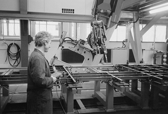
Investigations in Japan indicate that more than 50% of working accidents with robots can be attributed to faults in the electronic circuits of the control system. In the same investigations, “human error” was responsible for less than 20%. The logical conclusion of this finding is that hazards which are caused by system faults cannot be avoided by behavioural measures taken by human beings. Designers and operators therefore need to provide and implement technical safety measures (see figure 1).
Figure 1. Special operating control system for the setting up of a mobile welding robot
Accidents and Operating Modes
Fatal accidents involving industrial robots began to occur in the early 1980s. Statistics and investigations indicate that the majority of incidents and accidents do not take place in normal operation (automatic fulfilment of the assignment concerned). When working with industrial robot machines and installations, there is an emphasis on special operation modes such as commissioning, setting up, programming, test runs, checks, troubleshooting or maintenance. In these operating modes, persons are usually in a danger zone. The safety concept must protect personnel from negative events in these types of situations.
International Safety Requirements
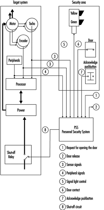
The 1989 EEC Machinery Directive (89/392/EEC (see the article “Safety principles for CNC machine tools” in this chapter and elsewhere in this Encyclopaedia)) establishes the principal safety and health requirements for machines. A machine is considered to be the sum total of interlinked parts or devices, of which at least one part or device can move and correspondingly has a function. Where industrial robots are concerned, it must be noted that the entire system, not just one single piece of equipment on the machine, must meet the safety requirements and be fitted with the appropriate safety devices. Hazard analysis and risk assessment are suitable methods of determining whether these requirements have been satisfied (see figure 2).
Figure 2. Block diagram for a personnel security system
Requirements and Safety Measures in Normal Operation
The use of robot technology places maximum demands on hazard analysis, risk assessment and safety concepts. For this reason, the following examples and suggestions can serve only as guidelines:
1. Given the safety goal that manual or physical access to hazardous areas involving automatic movements must be prevented, suggested solutions include the following:
- Prevent manual or physical access into danger zones by means of mechanical barriers.
- Use safety devices of the sort which respond when approached (light barriers, safety mats), and take care to switch off machinery safely when accessed or entered.
- Permit manual or physical access only when the entire system is in a safe state. For example, this can be achieved by the use of interlocking devices with closure mechanisms on the access doors.
2. Given the safety goal that no person may be injured as a result of the release of energy (flying parts or beams of energy), suggested solutions include:
- Design should prevent any release of energy (e.g., correspondingly dimensioned connections, passive gripper interlocking devices for gripper change mechanisms, etc.).
- Prevent the release of energy from the danger zone, for example, by a correspondingly dimensioned safety hood.
3. The interfaces between normal operation and special operation (e.g., door interlocking devices, light barriers, safety mats) are necessary to enable the safety control system to automatically recognize the presence of personnel.
Demands and Safety Measures in Special Operation Modes
Certain special operation modes (e.g., setting up, programming) on an industrial robot require movements which must be assessed directly at the site of operation. The relevant safety goal is that no movements may endanger the persons involved. The movements should be
- only of the scheduled style and speed
- prolonged only as long as instructed
- those which may be performed only if it can be guaranteed that no parts of the human body are in the danger zone.
A suggested solution to this goal could involve the use of special operating control systems which permit only controllable and manageable movements using acknowledgeable controls. The speed of movements is thus safely reduced (energy reduction by the connection of an isolation transformer or the use of fail-safe state monitoring equipment) and the safe condition is acknowledged before the control is allowed to activate (see figure 3).
Figure 3. Six-axis industrial robot in a safety cage with material gates

Demands on Safety Control Systems
One of the features of a safety control system must be that the required safety function is guaranteed to work whenever any faults arise. Industrial robot machines should be almost instantaneously directed from a hazardous state to a safe state. Safety control measures needed to achieve this include the following safety goals:
- A fault in the safety control system may not trigger off a hazardous state.
- A fault in the safety control system must be identified (immediately or at intervals).
Suggested solutions to providing reliable safety control systems would be:
- redundant and diverse layout of electro-mechanical control systems including test circuits
- redundant and diverse set-up of microprocessor control systems developed by different teams. This modern approach is considered to be state-of-the-art; for example, those complete with safety light barriers.
Safety Goals for the Construction and Use of Industrial Robots.
When industrial robots are built and used, both manufacturers as well as users are required to install state-of-the-art safety controls. Apart from the aspect of legal responsibility, there may also be a moral obligation to ensure that robot technology is also a safe technology.
Normal operation mode
The following safety conditions should be provided when robot machines are operating in the normal mode:
- The field of movement of the robot and the processing areas used by peripheral equipment must be secured in such a way as to prevent manual or physical access by persons to areas which are hazardous as a result of automatic movements.
- Protection should be provided so that flying workpieces or tools are not allowed to cause damage.
- No persons must be injured by parts, tools or workpieces ejected by the robot or by the release of energy, due to faulty gripper(s), gripper power failure, inadmissible speed, collision(s) or faulty workpiece(s).
- No persons may be injured by the release of energy or by parts ejected by peripheral equipment.
- Feed and removal apertures must be designed to prevent manual or physical access to areas which are hazardous as a result of automatic movements. This condition must also be fulfilled when production material is removed. If production material is fed to the robot automatically, no hazardous areas may be created by feed and removal apertures and the moving production material.
Special operation modes
The following safety conditions should be provided when robot machines are operating in special modes:
The following must be prevented during rectification of a breakdown in the production process:
- manual or physical access to areas which are hazardous due to automatic movements by the robot or by peripheral equipment
- hazards which arise from faulty behaviour on the part of the system or from inadmissible command input if persons or parts of the body are in the area exposed to hazardous movements
- hazardous movements or conditions initiated by the movement or removal of production material or waste products
- injuries caused by peripheral equipment
- movements that have to be carried out with the safety guard(s) for normal operation removed, to be carried out only within the operational scope and speed, and only as long as instructed. Additionally, no person(s) or parts of the body may be present in the area at risk.
The following safe conditions should be assured during set up:
No hazardous movements may be initiated as a result of a faulty command or incorrect command input.
- The replacement of robot machine or peripheral parts must not initiate any hazardous movements or conditions.
- If movements have to be carried out with the safety guard(s) for normal operation removed when conducting setting-up operations, such movements may be carried out only within the directed scope and speed and only as long as instructed. Additionally, no person(s) or parts of the body may be present in the area at risk.
- During setting-up operations, the peripheral equipment must not make any hazardous movements or initiate any hazardous conditions.
During programming, the following safety conditions are applicable:
- Manual or physical access to areas which are hazardous due to automatic movements must be prevented.
- If movements are carried out with the safety guard(s) for normal operation removed, the following conditions must be fulfilled:
- (a)Only the command to move may be carried out, and only for as long as it is issued.
- (b)Only controllable movements may be carried out (i.e., they must be clearly visible, low-speed movements).
- (c)Movements may be initiated only if they do not constitute a hazard to the programmer or other persons.
- Peripheral equipment must not represent a hazard to the programmer or other persons.
Safe test operations require the following precautions:
Prevent manual or physical access to areas which are hazardous due to automatic movements.
- Peripheral equipment must not be a source of danger.
When inspecting robot machines, safe procedures include the following:
- If it is necessary to enter the robot’s field of movement for inspection purposes, this is permissible only if the system is in a safe state.
- Hazards caused by faulty behaviour on the part of the system or by inadmissible command input must be prevented.
- Peripheral equipment must not be a source of danger to inspection personnel.
Troubleshooting often requires starting the robot machine while it is in a potentially hazardous condition, and special safe work procedures such as the following should be implemented:
- Access to areas which are hazardous as a result of automatic movements must be prevented.
- The starting up of a drive unit as a result of a faulty command or false command input must be prevented.
- In handling a defective part, all movements on the part of the robot must be prevented.
- Injuries caused by machine parts which are ejected or fall off must be prevented.
- If, during troubleshooting, movements have to be carried out with the safety guard(s) for normal operation removed, such movements may be carried out only within the scope and speed laid down and only as long as instructed. Additionally, no person(s) or parts of the body may be present in the area at risk.
- Injuries caused by peripheral equipment must be prevented.
Remedying a fault and maintenance work also may require start-up while the machine is in an unsafe condition, and therefore require the following precautions:
- The robot must not be able to start up.
- The handling of various machine parts, either manually or with ancillary equipment, must be possible without risk of exposure to hazards.
- It must not be possible to touch parts that are “live”.
- Injuries caused by the escape of liquid or gaseous media must be prevented.
- Injuries caused by peripheral equipment must be prevented.
Safety Principles for CNC Machine Tools
Whenever simple and conventional production equipment, such as machine tools, is automated, the result is complex technical systems as well as new hazards. This automation is achieved through the use of computer numeric control (CNC) systems on machine tools, called CNC machine tools (e.g., milling machines, machining centres, drills and grinders). In order to be able to identify the potential hazards inherent in automatic tools, the various operating modes of each system should be analysed. Previously conducted analyses indicate that a differentiation should be made between two types of operation: normal operation and special operation.
It is often impossible to prescribe the safety requirements for CNC machine tools in the shape of specific measures. This may be because there are too few regulations and standards specific to the equipment which provide concrete solutions. Safety requirements can be determined only if the possible hazards are identified systematically by conducting a hazard analysis, particularly if these complex technical systems are fitted with freely programmable control systems (as with CNC machine tools).
In the case of newly developed CNC machine tools, the manufacturer is obliged to carry out a hazard analysis on the equipment in order to identify whatever dangers may be present and to show by means of constructive solutions that all dangers to persons, in all of the different operating modes, are eliminated. All the hazards identified must be subjected to a risk assessment wherein each risk of an event is dependent on the scope of damage and the frequency with which it may occur. The hazard to be assessed is also given a risk category (minimized, normal, increased). Wherever the risk cannot be accepted on the basis of the risk assessment, solutions (safety measures) must be found. The purpose of these solutions is to reduce the frequency of occurrence and the scope of damage of an unplanned and potentially hazardous incident (an “event”).
The approaches to solutions for normal and increased risks are to be found in indirect and direct safety technology; for minimized risks, they are to be found in referral safety technology:
- Direct safety technology. Care is taken at the design stage to eliminate any hazards (e.g., the elimination of shearing and trapping points).
- Indirect safety technology. The hazard remains. However, the addition of technical arrangements prevents the hazard from turning into an event (e.g., such arrangements may include the prevention of access to dangerous moving parts by means of physical safety hoods, the provision of safety devices which turn power off, shielding from flying parts using safety guards, etc.).
- Referral safety technology. This applies only to residual hazards and minimized risks—that is, hazards which can lead to an event as a result of human factors. The occurrence of such an event can be prevented by appropriate behaviour on the part of the person concerned (e.g., instructions on behaviour in the operating and maintenance manuals, personnel training, etc.).
International Safety Requirements
The EC Machinery Directive (89/392/EEC) of 1989 lays down the principal safety and health requirements for machines. (According to the Machinery Directive, a machine is considered to be the sum total of interlinked parts or devices, of which at least one can move and correspondingly has a function.) In addition, individual standards are created by international standardization bodies to illustrate possible solutions (e.g., by attending to fundamental safety aspects, or by examining electrical equipment fitted to industrial machinery). The aim of these standards is to specify protection goals. These international safety requirements give manufacturers the necessary legal basis to specify these requirements in the above-mentioned hazard analyses and risk assessments.
Operating Modes
When using machine tools, a differentiation is made between normal operation and special operation. Statistics and investigations indicate that the majority of incidents and accidents do not take place in normal operation (i.e., during the automatic fulfilment of the assignment concerned). With these types of machines and installations, there is an emphasis on special modes of operations such as commissioning, setting up, programming, test runs, checks, troubleshooting or maintenance. In these operating modes, persons are usually in a danger zone. The safety concept must protect personnel from harmful events in these types of situations.
Normal operation
The following applies to automatic machines when carrying out normal operation: (1) the machine fulfils the assignment for which it was designed and constructed without any further intervention by the operator, and (2) applied to a simple turning machine, this means that a workpiece is turned to the correct shape and chips are produced. If the workpiece is changed manually, changing the workpiece is a special mode of operation.
Special modes of operation
Special modes of operation are working processes which allow normal operation. Under this heading, for example, one would include workpiece or tool changes, rectifying a fault in a production process, rectifying a machine fault, setting up, programming, test runs, cleaning and maintenance. In normal operation, automatic systems fulfil their assignments independently. From the viewpoint of working safety, however, automatic normal operation becomes critical when the operator has to intervene working processes. Under no circumstances may the persons intervening in such processes be exposed to hazards.
Personnel
Consideration must be given to the persons working in the various modes of operation as well as to third parties when safeguarding machine tools. Third parties also include those indirectly concerned with the machine, such as supervisors, inspectors, assistants for transporting material and dismantling work, visitors and others.
Demands and Safety Measures for Machine Accessories
Interventions for jobs in special operation modes mean that special accessories have to be used to assure work can be conducted safely. The first type of accessories include equipment and items used to intervene in the automatic process without the operator’s having to access a hazardous zone. This type of accessory includes (1) chip hooks and tongs which have been so designed that chips in the machining area can be removed or pulled away through the apertures provided in the safety guards, and (2) workpiece clamping devices with which the production material can be manually inserted into or removed from an automatic cycle
Various special modes of operation—for example, remedial work or maintenance work—make it necessary for personnel to intervene in a system. In these cases, too, there is a whole range of machine accessories designed to increase working safety—for example, devices to handle heavy grinding wheels when the latter are changed on grinders, as well as special crane slings for dismantling or erecting heavy components when machines are overhauled. These devices are the second type of machine accessory for increasing safety during work in special operations. Special operation control systems can also be considered to represent a second type of machine accessory. Particular activities can be carried out safely with such accessories—for example, a device can be set up in the machine axes when feed movements are necessary with the safety guards open.
These special operation control systems must satisfy particular safety requirements. For example, they must ensure that only the movement requested is carried out in the way requested and only for as long as requested. The special operation control system must therefore be designed in such a way as to prevent any faulty action from turning into hazardous movements or states.
Equipment which increases the degree of automation of an installation can be considered to be a third type of machine accessory for increasing working safety. Actions which were previously carried out manually are done automatically by the machine in normal operation, such as equipment including portal loaders, which change the workpieces on machine tools automatically. The safeguarding of automatic normal operation causes few problems because the intervention of an operator in the course of events is unnecessary and because possible interventions can be prevented by safety devices.
Requirements and Safety Measures for the Automation of Machine Tools
Unfortunately, automation has not led to the elimination of accidents in production plants. Investigations simply show a shift in the occurrence of accidents from normal to special operation, primarily due to the automation of normal operation so that interventions in the course of production are no longer necessary and personnel are thus no longer exposed to danger. On the other hand, highly automatic machines are complex systems which are difficult to assess when faults occur. Even the specialists employed to rectify faults are not always able to do so without incurring accidents. The amount of software needed to operate increasingly complex machines is growing in volume and complexity, with the result that an increasing number of electrical and commissioning engineers suffer accidents. There is no such thing as flawless software, and changes in software often lead to changes elsewhere which were neither expected nor wanted. In order to prevent safety from being affected, hazardous faulty behaviour caused by external influence and component failures must not be possible. This condition can be fulfilled only if the safety circuit is designed as simply as possible and is separate from the rest of the controls. The elements or sub-assemblies used in the safety circuit must also be fail-safe.
It is the task of the designer to develop designs that satisfy safety requirements. The designer cannot avoid having to consider the necessary working procedures, including the special modes of operation, with great care. Analyses must be made to determine which safe work procedures are necessary, and the operating personnel must become familiar with them. In the majority of cases, a control system for special operation will be necessary. The control system usually observes or regulates a movement, while at the same time, no other movement must be initiated (as no other movement is needed for this work, and thus none is expected by the operator). The control system does not necessarily have to carry out the same assignments in the various modes of special operation.
Requirements and Safety Measures in Normal and Special Modes of Operation
Normal operation
The specification of safety goals should not impede technical progress because adapted solutions can be selected. The use of CNC machine tools makes maximum demands on hazard analysis, risk assessment and safety concepts. The following describes several safety goals and possible solutions in greater detail.
Safety goal
- Manual or physical access to hazardous areas during automatic movements must be prevented.
Possible solutions
- Prevent manual or physical access into danger zones by means of mechanical barriers.
- Provide safety devices that respond when approached (light barriers, safety mats) and switch off machinery safely during interventions or entry.
- Allow manual or physical access to machinery (or its vicinity) only when the entire system is in a safe state (e.g., by using interlocking devices with closure mechanisms on the access doors).
Safety goal
- The possibility of any persons being injured as a result of the release of energy (flying parts or beams of energy) should be eliminated.
Possible solution
- Prevent the release of energy from the danger zone—for example, by a correspondingly dimensioned safety hood.
Special operation
The interfaces between normal operation and special operation (e.g., door interlocking devices, light barriers, safety mats) are necessary to enable the safety control system to recognize automatically the presence of personnel. The following describes certain special operation modes (e.g., setting up, programming) on CNC machine tools which require movements that must be assessed directly at the site of operation.
Safety goals
- Movements must take place only in such a way that they cannot be a hazard for the persons concerned. Such movements must be executed only in the scheduled style and speed and continued only as long as instructed.
- They are to be attempted only if it can be guaranteed that no parts of the human body are in the danger zone.
Possible solution
- Install special operating control systems which permit only controllable and manageable movements using finger-tip control via “acknowledge-type” push buttons. The speed of movements is thus safely reduced (provided that energy has been reduced by means of an isolation transformer or similar monitoring equipment).
Demands on Safety Control Systems
One of the features of a safety control system must be that the safety function is guaranteed to work whenever any faults arise so as to direct processes from a hazardous state to a safe state.
Safety goals
- A fault in the safety control system must not trigger off a dangerous state.
- A fault in the safety control system must be identified (immediately or at intervals).
Possible solutions
- Put in place a redundant and diverse layout of electro-mechanical control systems, including test circuits.
- Put in place a redundant and diverse set-up of microprocessor control systems developed by different teams. This approach is considered to be state of the art, for example, in the case of safety light barriers.
Conclusion
It is apparent that the increasing trend in accidents in normal and special modes of operation cannot be halted without a clear and unmistakable safety concept. This fact must be taken into account in the preparation of safety regulations and guidelines. New guidelines in the shape of safety goals are necessary in order to allow advanced solutions. This objective enables designers to choose the optimum solution for a specific case while at the same time demonstrating the safety features of their machines in a fairly simple way by describing a solution to each safety goal. This solution can then be compared with other existing and accepted solutions, and if it is better or at least of equal value, a new solution can then be chosen. In this way, progress is not hampered by narrowly formulated regulations.
Main Features of the EEC Machinery Directive
The Council Directive of 14 June 1989 on the approximation of the laws of the Member States relating machinery (89/392/EEC) applies to each individual state.
- Each individual state must integrate the directive in its legislation.
- Valid from 1 January 1993.
- Requires that all manufacturers adhere to the state of the art.
- The manufacturer must produce a technical construction file which contains full information on all fundamental aspects of safety and health care.
- The manufacturer must issue the declaration of conformity and the CE marking of the machines.
- Failure to place a complete technical documentation at the disposal of a state supervisory centre is considered to represent the non-fulfilment of the machine guidelines. A pan-EEC sales prohibition may be the consequence.
Safety Goals for the Construction and Use of CNC Machine Tools
1. Lathes
1.1 Normal mode of operation
1.1.1 The work area is to be safeguarded so that it is impossible to reach or step into the danger zones of automatic movements, either intentionally or unintentionally.
1.1.2 The tool magazine is to be safeguarded so that it is impossible to reach or step into the danger zones of automatic movements, either intentionally or unintentionally.
1.1.3 The workpiece magazine is to be safeguarded so that it is impossible to reach or step into the danger zones of automatic movements, either intentionally or unintentionally.
1.1.4 Chip removal must not result in personal injury due to the chips or moving parts of the machine.
1.1.5 Personal injuries resulting from reaching into drive systems must be prevented.
1.1.6 The possibility of reaching into the danger zones of moving chip conveyors must be prevented.
1.1.7 No personal injury to operators or third persons must result from flying workpieces or parts thereof.
For example, this can occur
- due to insufficient clamping
- due to inadmissible cutting force
- due to inadmissible rotation speed
- due to collision with the tool or machine parts
- due to workpiece breakage
- due to defective clamping fixtures
- due to power failure
1.1.8 No personal injury must result from flying workpiece clamping fixtures.
1.1.9 No personal injury must result from flying chips.
1.1.10 No personal injury must result from flying tools or parts thereof.
For example, this can occur
- due to material defects
- due to inadmissible cutting force
- due to a collision with the workpiece or a machine part
- due to inadequate clamping or tightening
1.2 Special modes of operation
1.2.1 Workpiece changing.
1.2.1.1 Workpiece clamping must be done in such a way that no parts of the body can become trapped between closing clamping fixtures and workpiece or between the advancing sleeve tip and workpiece.
1.2.1.2 The starting of a drive (spindles, axes, sleeves, turret heads or chip conveyors) as a consequence of a defective command or invalid command must be prevented.
1.2.1.3 It must be possible to manipulate the workpiece manually or with tools without danger.
1.2.2 Tool changing in tool holder or tool turret head.
1.2.2.1 Danger resulting from the defective behaviour of the system or due to entering an invalid command must be prevented.
1.2.3 Tool changing in the tool magazine.
1.2.3.1 Movements in the tool magazine resulting from a defective or invalid command must be prevented during tool changing.
1.2.3.2 It must not be possible to reach into other moving machine parts from the tool loading station.
1.2.3.3 It must not be possible to reach into danger zones on the further movement of the tool magazine or during the search. If taking place with the guards for normal operation mode removed, these movements may only be of the designated kind and only be carried out during the period of time ordered and only when it can be ensured that no parts of the body are in these danger zones.
1.2.4 Measurement check.
1.2.4.1 Reaching into the work area must only be possible after all movements have been brought to a standstill.
1.2.4.2 The starting of a drive resulting from a defective command or invalid command input must be prevented.
1.2.5 Set-up.
1.2.5.1 If movements are executed during set-up with the guards for normal mode of operation removed, then the operator must be safeguarded by another means.
1.2.5.2 No dangerous movements or changes of movements must be initiated as a result of a defective command or invalid command input.
1.2.6 Programming.
1.2.6.1 No movements may be initiated during programming which endanger a person in the work area.
1.2.7 Production fault.
1.2.7.1 The starting of a drive resulting from a defective command on invalid command input setpoint must be prevented.
1.2.7.2 No dangerous movements or situations are to be initiated by the movement or removal of the workpiece or waste.
1.2.7.3 Where movements have to take place with the guards for the normal mode of operation removed, these movements may only be of the kind designated and only executed for the period of time ordered and only when it can be ensured that no parts of the body are in these danger zones.
1.2.8 Troubleshooting.
1.2.8.1 Reaching into the danger zones of automatic movements must be prevented.
1.2.8.2 The starting of a drive as a result of a defective command or invalid command input must be prevented.
1.2.8.3 A movement of the machine on manipulation of the defective part must be prevented.
1.2.8.4 Personal injury resulting from a machine part splintering off or dropping must be prevented.
1.2.8.5 If, during troubleshooting, movements have to take place with the guards for the normal mode of operation removed, these movements may only be of the kind designated and only executed for the period of time ordered and only when it can be ensured that no parts of the body are in these danger zones.
1.2.9 Machine malfunction and repair.
1.2.9.1 The machine must be prevented from starting.
1.2.9.2 Manipulation of the different parts of the machine must be possible either manually or with tools without any danger.
1.2.9.3 It must not be possible to touch live parts of the machine.
1.2.9.4 Personal injury must not result from the issue of fluid or gaseous media.
2. Milling machines
2.1 Normal mode of operation
2.1.1 The work area is to be safeguarded so that it is impossible to reach or step into the danger zones of automatic movements, either intentionally or unintentionally.
2.1.2 Chip removal must not result in personal injury due to the chips or moving parts of the machine.
2.1.3 Personal injuries resulting from reaching into drive systems must be prevented.
No personal injury to operators or third persons must result from flying workpieces or parts thereof.
For example, this can occur
- due to insufficient clamping
- due to inadmissible cutting force
- due to collision with the tool or machine parts
- due to workpiece breakage
- due to defective clamping fixtures
- due to power failure
2.1.4 No personal injury must result from flying workpiece clamping fixtures.
2.1.5 No personal injury must result from flying chips.
2.1.6 No personal injury must result from flying tools or parts thereof.
For example, this can occur
- due to material defects
- due to inadmissible speed of rotation
- due to inadmissible cutting force
- due to collision with workpiece or machine part
- due to inadequate clamping or tightening
- due to power failure
Special modes of operation
2.2.1 Workpiece changing.
2.2.1.1 Where power-operated clamping fixtures are used, it must not be possible for parts of the body to become trapped between the closing parts of the clamping fixture and the workpiece.
2.2.1.2 The starting of a drive (spindle, axis) resulting from a defective command or invalid command input must be prevented.
2.2.1.3 The manipulation of the workpiece must be possible manually or with tools without any danger.
2.2.2 Tool changing.
2.2.2.1 The starting of a drive resulting from a defective command or invalid command input must be prevented.
2.2.2.2 It must not be possible for fingers to become trapped when putting in tools.
2.2.3 Measurement check.
2.2.3.1 Reaching into the work area must only be possible after all movements have been brought to a standstill.
2.2.3.2 The starting of a drive resulting from a defective command or invalid command input must be prevented.
2.2.4 Set-up.
2.2.4.1 If movements are executed during set-up with guards for normal mode of operation removed, the operator must be safeguarded by another means.
2.2.4.2 No dangerous movements or changes of movements must be initiated as a result of a defective command or invalid command input.
2.2.5 Programming.
2.2.5.1 No movements must be initiated during programming which endanger a person in the work area.
2.2.6 Production fault.
2.2.6.1 The starting of drive resulting from a defective command or invalid command input must be prevented.
2.2.6.2 No dangerous movements or situations must be initiated by the movement or removal of the workpiece or waste.
2.2.6.3 Where movements have to take place with the guards for the normal mode of operation removed, these movements may only be of the kind designated and only executed for the period of time ordered and only when it can be ensured that no parts of the body are in these danger zones.
2.2.7 Troubleshooting.
2.2.7.1 Reaching into the danger zones of automatic movements must be prevented.
2.2.7.2 The starting of a drive as a result of a defective command or invalid command input must be prevented.
2.2.7.3 Any movement of the machine on manipulation of the defective part must be prevented.
2.2.7.4 Personal injury resulting from a machine part splintering off or dropping must be prevented.
2.2.7.5 If, during troubleshooting, movements have to take place with the guards for the normal mode of operation removed, these movements may only be of the kind designated and only executed for the period of time ordered and only when it can be ensured that no parts of the body are in these danger zones.
2.2.8 Machine malfunction and repair.
2.2.8.1 Starting the machine must be prevented.
2.2.8.2 Manipulation of the different parts of the machine must be possible manually or with tools without any danger.
2.2.8.3 It must not be possible to touch live parts of the machine.
2.2.8.4 Personal injury must not result from the issue of fluid or gaseous media.
3. Machining centres
3.1 Normal mode of operation
3.1.1 The work area must be safeguarded so that is impossible to reach or step into the danger zones of automatic movements, either intentionally or unintentionally.
3.1.2 The tool magazine must be safeguarded so that it is impossible to reach or step into the danger zones of automatic movements.
3.1.3 The workpiece magazine must be safeguarded so that it is impossible to reach or step into the danger zones of automatic movements.
3.1.4 Chip removal must not result in personal injury due to the chips or moving parts of the machine.
3.1.5 Personal injuries resulting from reaching into drive systems must be prevented.
3.1.6 The possibility of reaching into danger zones of moving chip conveyors (screw conveyors, etc.) must be prevented.
3.1.7 No personal injury to operators or third persons must result from flying workpieces or parts thereof.
For example, this can occur
- due to insufficient clamping
- due to inadmissible cutting force
- due to collision with the tool or machine parts
- due to workpiece breakage
- due to defective clamping fixtures
- due to changing to the wrong workpiece
- due to power failure
3.1.8 No personal injury must result from flying workpiece clamping fixtures.
3.1.9 No personal injury must result from flying chips.
3.1.10 No personal injury must result from flying tools or parts thereof.
For example, this can occur
- due to material defects
- due to inadmissible speed of rotation
- due to inadmissible cutting force
- due to collision with workpiece or machine part
- due to inadequate clamping or tightening
- due to the tool flying out of the tool changer
- due to selecting the wrong tool
- due to power failure
3.2 Special modes of operation
3.2.1 Workpiece changing.
3.2.1.1 Where power-operated clamping fixtures are used, it must not be possible for parts of the body to become trapped between the closing parts of the clamping fixture and the workpiece.
3.2.1.2 The starting of a drive resulting from a defective command or invalid command input must be prevented.
3.2.1.3 It must be possible to manipulate the workpiece manually or with tools without any danger.
3.2.1.4 Where workpieces are changed in a clamping station, it must not be possible from this location to reach or step into automatic movement sequences of the machine or workpiece magazine. No movements must be initiated by the control while a person is present in the clamping zone. The automatic insertion of the clamped workpiece into the machine or workpiece magazine is only to take place when the clamping station is also safeguarded with a protective system corresponding to that for normal mode of operation.
3.2.2 Tool changing in the spindle.
3.2.2.1 The starting of a drive resulting from a defective command or invalid command input must be prevented.
3.2.2.2 It must not be possible for fingers to become trapped when putting in tools.
3.2.3 Tool changing in tool magazine.
3.2.3.1 Movements in the tool magazine resulting from defective commands or invalid command input must be prevented during tool changing.
3.2.3.2 It must not be possible to reach into other moving machine parts from the tool loading station.
3.2.3.3 It must not be possible to reach into danger zones on the further movement of the tool magazine or during the search. If taking place with the guards for the normal mode of operation removed, these movements may only be of the kind designated and only executed for the period of time ordered and only when it can be ensured that no parts of the body are in these danger zones.
3.2.4 Measurement check.
3.2.4.1 Reaching into the work area must only be possible after all movements have been brought to a standstill.
3.2.4.2 The starting of a drive resulting from a defective command or invalid command input must be prevented.
3.2.5 Set-up.
3.2.5.1 If movements are executed during set-up with the guards for normal mode of operation removed, then the operator must be safeguarded by another means.
3.2.5.2 No dangerous movements or changes of movement must be initiated as a result of a defective command or invalid command input.
3.2.6 Programming.
3.2.6.1 No movements must be initiated during programming which endanger a person in the work area.
3.2.7 Production fault.
3.2.7.1 The starting of a drive resulting from a defective command or invalid command input must be prevented.
3.2.7.2 No dangerous movements or situations must be initiated by the movement or removal of the workpiece or waste.
3.2.7.3 Where movements have to take place with the guards for the normal mode of operation removed, these movements may only be of the kind designated and only executed for the period of time ordered and only when it can be ensured that no parts of the body are in these danger zones.
3.2.8 Troubleshooting.
3.2.8.1 Reaching into the danger zones of automatic movements must be prevented.
3.2.8.2 The starting of a drive as a result of a defective command or invalid command input must be prevented.
3.2.8.3 Any movement of the machine on manipulation of the defective part must be prevented.
3.2.8.4 Personal injury resulting from a machine part splintering off or dropping must be prevented.
3.2.8.5 If, during troubleshooting, movements have to take place with the guards for the normal mode of operation removed, these movements may only be of the kind designated and only executed for the period of time ordered and only when it can be ensured that no parts of the body are in these danger zones.
3.2.9 Machine malfunction and repair.
3.2.9.1 Starting the machine must be prevented.
3.2.9.2 Manipulation of the different parts of the machine must be possible manually or with tools without any danger.
3.2.9.3 It must not be possible to touch live parts of the machine.
3.2.9.4 Personal injury must not result from the issue of fluid or gaseous media.
4. Grinding machines
4.1 Normal mode of operation
4.1.1 The work area is to be safeguarded so that it is impossible to reach or step into the danger zones of automatic movements, either intentionally or unintentionally.
4.1.2 Personal injuries resulting from reaching into drive systems must be prevented.
4.1.3 No personal injury to operators or third persons must result from flying workpieces or parts thereof.
For example, this can occur
- due to insufficient clamping
- due to inadmissible cutting force
- due to inadmissible rotation speed
- due to collision with the tool or machine parts
- due to workpiece breakage
- due to defective clamping fixtures
- due to power failure
4.1.4 No personal injury must result from flying workpiece clamping fixtures.
4.1.5 No personal injury or fires must result from sparking.
4.1.6 No personal injury must result from flying parts of grinding wheels.
For example, this can occur
- due to inadmissible rotation speed
- due to inadmissible cutting force
- due to material defects
- due to collision with workpiece or machine part
- due to inadequate clamping (flanges)
- due to using incorrect grinding wheel
Special modes of operation
4.2.1 Workpiece changing.
4.2.1.1 Where power-operated clamping fixtures are used, it must not be possible for parts of the body to become trapped between the closing parts of the clamping fixture and the workpiece.
4.2.1.2 The starting of a feed drive resulting from a defective command or invalid command input must be prevented.
4.2.1.3 Personal injury caused by the rotating grinding wheel must be prevented when manipulating the workpiece.
4.2.1.4 Personal injury resulting from a bursting grinding wheel must not be possible.
4.2.1.5 The manipulation of the workpiece must be possible manually or with tools without any danger.
4.2.2 Tool changing (grinding wheel changing)
4.2.2.1 The starting of a feed drive resulting from .a defective command or invalid command input must be prevented.
4.2.2.2 Personal injury caused by the rotating grinding wheel must not be possible during measuring procedures.
4.2.2.3 Personal injury resulting from a bursting grinding wheel must not be possible.
4.2.3 Measurement check.
4.2.3.1 The starting of a feed drive resulting from a defective command or invalid command input must be prevented.
4.2.3.2 Personal injury caused by the rotating grinding wheel must not be possible during measuring procedures.
4.2.3.3 Personal injury resulting from a bursting grinding wheel must not be possible.
4.2.4. Set-up.
4.2.4.1 If movements are executed during set-up with the guards for normal mode of operation removed, then the operator must be safeguarded by another means.
4.2.4.2 No dangerous movements or changes of movement must be initiated as a result of a defective command or invalid command input.
4.2.5 Programming.
4.2.5.1 No movements must be initiated during programming which endanger a person in the work area.
4.2.6 Production fault.
4.2.6.1 The starting of a feed drive resulting from a defective command or invalid command input must be prevented.
4.2.6.2 No dangerous movements or situations must be initiated by the movement or removal of the workpiece or waste.
4.2.6.3 Where movements have to take place with the guards for the normal mode of operation removed, these movements may only be of the kind designated and only executed for the period of time ordered and only when it can be ensured that no parts of the body are in these danger zones.
4.2.6.4 Personal injury caused by the rotating grinding wheel must be prevented.
4.2.6.5 Personal injury resulting from a bursting grinding wheel must not be possible.
4.2.7 Troubleshooting.
4.2.7.1 Reaching into the danger zones of automatic movements must be prevented.
4.2.7.2 The starting of a drive as a result of a defective command or invalid command input must be prevented.
4.2.7.3 Any movement of the machine on manipulation of the defective part must be prevented.
4.2.7.4 Personal injury resulting from a machine part splintering off or dropping must be prevented.
4.2.7.5 Personal injury caused the operator’s contacting or by the bursting of the rotating grinding wheel must be prevented.
4.2.7.6 If, during troubleshooting, movements have to take place with the guards for the normal mode of operation removed, these movements may only be of the kind designated and only executed for the period of time ordered and only when it can be ensured that no parts of the body are in these danger zones.
4.2.8 Machine malfunction and repair.
4.2.8.1 Starting the machine must be prevented.
4.2.8.2 Manipulation of the different parts of the machine must be possible manually or with tools without any danger.
4.2.8.3 It must not be possible to touch live parts of the machine.
4.2.8.4 Personal injury must not result from the issue of fluid or gaseous media.
Principles for the Design of Safe Control Systems
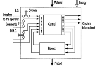
It is generally agreed that control systems must be safe during use. With this in mind, most modern control systems are designed as shown in figure 1.
Figure 1. General design of control systems
The simplest way to make a control system safe is to construct an impenetrable wall around it so as to prevent human access or interference into the danger zone. Such a system would be very safe, albeit impractical, since it would be impossible to gain access in order to perform most testing, repair and adjustment work. Because access to danger zones must be permitted under certain conditions, protective measures other than just walls, fences and the like are required to facilitate production, installation, servicing and maintenance.
Some of these protective measures can be partly or fully integrated into control systems, as follows:
- Movement can be stopped immediately should anybody enter the danger zone, by means of emergency stop (ES) buttons.
- Push-button controls permit movement only when the push-button is activated.
- Double-hand controls (DHC) permit movement only when both hands are engaged in depressing the two control elements (thus ensuring that hands are kept away from the danger zones).
These types of protective measures are activated by operators. However, because human beings often represent a weak point in applications, many functions, such as the following, are performed automatically:
- Movements of robot arms during the servicing or “teach-in” are very slow. Nonetheless, speed is continuously monitored. If, because of a control system failure, the speed of automatic robot arms were to increase unexpectedly during either the servicing or teach-in period, the monitoring system would activate and immediately terminate movement.
- A light barrier is provided to prevent access into a danger zone. If the light beam is interrupted, the machine will stop automatically.
Normal function of control systems is the most important precondition for production. If a production function is interrupted due to a control failure, it is at most inconvenient but not hazardous. If a safety-relevant function is not performed, it could result in lost production, equipment damage, injury or even death. Therefore, safety-relevant control system functions must be more reliable and safer than normal control system functions. According to European Council Directive 89/392/EEC (Machine Guidelines), control systems must be designed and constructed so that they are safe and reliable.
Controls consist of a number of components connected together so as to perform one or more functions. Controls are subdivided into channels. A channel is the part of a control that performs a specific function (e.g., start, stop, emergency stop). Physically, the channel is created by a string of components (transistors, diodes, relays, gates, etc.) through which, from one component to the next, (mostly electrical) information representing that function is transferred from input to output.
In designing control channels for safety-relevant functions (those functions which involve humans), the following requirements must be fulfilled:
- Components used in control channels with safety-relevant functions must be able to withstand the rigours of normal use. Generally, they must be sufficiently reliable.
- Errors in the logic must not cause dangerous situations. Generally, the safety-relevant channel is to be sufficiently failure proof.
- External influences (factors) should not lead to temporary or permanent failures in safety-relevant channels.
Reliability
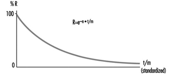
Reliability is the ability of a control channel or component to perform a required function under specified conditions for a given period of time without failing. (Probability for specific components or control channels can be calculated using suitable methods.) Reliability must always be specified for a specific time value. Generally, reliability can be expressed by the formula in figure 2.
Figure 2. Reliability formula
Reliability of complex systems
Systems are built from components. If the reliabilities of the components are known, the reliability of the system as a whole can be calculated. In such cases, the following apply:
Serial systems
The total reliability Rtot of a serial system consisting of N components of the same reliability RC is calculated as in figure 3.
Figure 3. Reliability graph of serially connected components
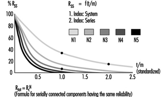
The total reliability is lower than the reliability of the least reliable component. As the number of serially connected components increases, the total reliability of the chain falls significantly.
Parallel systems
The total reliability Rtot of a parallel system consisting of N components of the same reliability RC is calculated as in figure 4.
Figure 4. Reliability graph of parallel connected components
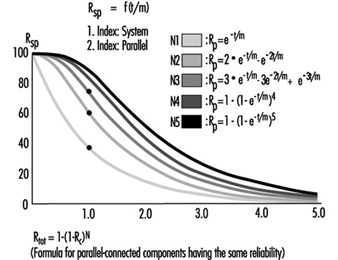
Total reliability can be improved significantly through the parallel connection of two or more components.
Figure 5 illustrates a practical example. Note that the circuitry will switch off the motor more reliably. Even if relay A or B fails to open its contact, the motor will still be switched off.
Figure 5. Practical example of figure 4

To calculate the total reliability of a channel is simple if all necessary component reliabilities are known and available. In the case of complex components (integrated circuits, microprocessors, etc.) the calculation of the total reliability is difficult or impossible if the necessary information is not published by the manufacturer.
Safety
When professionals speak about safety and call for safe machines, they mean the safety of the entire machine or system. This safety is, however, too general, and not precisely enough defined for the designer of controls. The following definition of safety may be practical and usable to designers of control circuitry: Safety is the ability of a control system to perform the required function within prescribed limits, for a given duration, even when anticipated fault(s) occur. Consequently, it must be clarified during the design how “safe” the safety-related channel must be. (The designer can develop a channel that is safe against first failure, against any one failure, against two failures, etc.) Furthermore, a channel that performs a function which is used to prevent accidents may be essentially reliable, but it does not have to be inevitably safe against failures. This may be best explained by the following examples:
Example 1
The example illustrated in figure 6 is a safety-relevant control channel performing the required safety function. The first component may be a switch that monitors, for example, the position of an access door to a dangerous area. The last component is a motor which drives moving mechanical parts within the danger area.
Figure 6. A safety-relevant control channel performing the required safety function
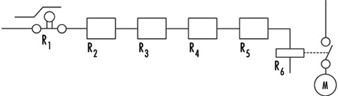
The required safety function in this case is a dual one: If the door is closed, the motor may run. If the door is open, the motor must be switched off. Knowing reliabilities R1 to R6, it is possible to calculate reliability Rtot. Designers should use reliable components in order to maintain sufficiently high reliability of the whole control system (i.e., the probability that this function may still be performed in, say, even 20 years should be accounted for in the design). As a result, designers must fulfil two tasks: (1) the circuitry must perform the required function, and (2) the reliability of the components and of the whole control channel must be adequate.
The following question should now be asked: Will the aforementioned channel perform the required safety functions even if a failure occurs in the system (e.g., if a relay contact sticks or a component malfunctions)? The answer is “No”. The reason is that a single control channel consisting only of serially connected components and working with static signals is not safe against one failure. The channel can have only a certain reliability, which guarantees the probability that the function will be carried out. In such situations, safety is always meant as failure related.
Example 2
If a control channel is to be both reliable and safe, the design must be modified as in figure 7. The example illustrated is a safety-relevant control channel consisting of two fully separated subchannels.
Figure 7. A safety-relevant control channel with two fully separate subchannels
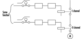
This design is safe against the first failure (and possible further failures in the same subchannel), but is not safe against two failures which may occur in two different subchannels (simultaneously or at different times) because there is no failure detection circuit. Consequently, initially both subchannels work with a high reliability (see parallel system), but after the first failure only one subchannel will work, and reliability decreases. Should a second failure occur in the subchannel still working, both will have then failed, and the safety function will no longer be performed.
Example 3
The example illustrated in figure 8 is a safety-relevant control channel consisting of two fully separate subchannels which monitor each other.
Figure 8. A safety-relevant control channel with two fully separate subchannels which monitor each other
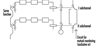
Such a design is failure safe because after any failure, only one subchannel will be non-functional, while the other subchannel remains available and will perform the safety function. Moreover, the design has a failure detection circuit. If, due to a failure, both subchannels fail to work in the same way, this condition will be detected by “exclusive or” circuitry, with the result that the machine will be automatically switched off. This is one of the best ways of designing machine controls—designing safety-relevant subchannels. They are safe against one failure and at the same time provide enough reliability so that the chances that two failures will occur simultaneously is minuscule.
Redundancy
It is apparent that there are various methods by which a designer may improve reliability and/or safety (against failure). The previous examples illustrate how a function (i.e., door closed, motor may run; door opened, motor must be stopped) can be realized by various solutions. Some methods are very simple (one subchannel) and others more complicated (two subchannels with mutual supervising). (See figure 9.)
Figure 9. Reliability of redundant systems with or without failure detection
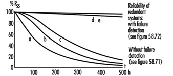
There is a certain redundancy in the complex circuitry and/or components in comparison with the simple ones. Redundancy can be defined as follows: (1) Redundancy is the presence of more means (components, channels, higher safety factors, additional tests and so on) than are really necessary for the simple fulfilling of the desired function; (2) redundancy obviously does not “improve” the function, which is performed anyway. Redundancy only improves reliability and/or safety.
Some safety professionals believe that redundancy is only the doubling or tripling, and so on, of the system. This is a very limited interpretation, as redundancy may be interpreted much more broadly and flexibly. Redundancy may be not only included in the hardware; it may be included in the software too. Improving the safety factor (e.g., a stronger rope instead of a weaker rope) may also be considered as a form of redundancy.
Entropy
Entropy, a term found mostly in thermodynamics and astronomy, may be defined as follows: Everything tends towards decay. Therefore, it is absolutely certain that all components, subsystems or systems, independently of the technology in use, will fail sometime. This means that there are no 100% reliable and/or safe systems, subsystems or components. All of them are merely more or less reliable and safe, depending on the structure’s complexity. The failures which inevitably occur earlier or later demonstrate the action of entropy.
The only means available to designers to counter entropy is redundancy, which is achieved by (a) introducing more reliability into the components and (b) providing more safety throughout the circuit architecture. Only by sufficiently raising the probability that the required function will be performed for the required period of time, can designers in some degree defend against entropy.
Risk Assessment
The greater the potential risk, the higher the reliability and/or safety (against failures) that is required (and vice versa). This is illustrated by the following two cases:
Case 1
Access to the mould tool fixed in an injection moulding machine is safeguarded by a door. If the door is closed, the machine may work, and if the door is opened, all dangerous movements have to be stopped. Under no circumstances (even in case of failure in the safety-related channel) may any movements, especially those which operate the tool, occur.
Case 2
Access to an automatically controlled assembly line that assembles small plastic components under pneumatic pressure is guarded by a door. If this door is opened, the line will have to be stopped.
In Case 1, if the door-supervising control system should fail, a serious injury may occur if the tool is closed unexpectedly. In Case 2, only slight injury or insignificant harm may result if the door-supervising control system fails.
It is obvious that in the first case much more redundancy must be introduced to attain the reliability and/or safety (against failure) required to protect against extreme high risk. In fact, according to European Standard EN 201, the supervising control system of the injection moulding machine door has to have three channels; two of which are electrical and mutually supervised and one of which is mostly equipped with hydraulics and testing circuits. All these three supervising functions relate to the same door.
Conversely, in applications like that described in Case 2, a single channel activated by a switch with positive action is appropriate to the risk.
Control Categories
Because all of the above considerations are generally based on information theory and consequently are valid for all technologies, it does not matter whether the control system is based on electronic, electro-mechanical, mechanical, hydraulic or pneumatic components (or a mixture of them), or on some other technology. The inventiveness of the designer on the one hand and economic questions on the other hand are the primary factors affecting a nearly endless number of solutions as to how to realize safety-relevant channels.
To prevent confusion, it is practical to set certain sorting criteria. The most typical channel structures used in machine controls for performing safety-related functions are categorized according to:
- reliability
- behaviour in case of failure
- failure-disclosing time.
Their combinations (not all possible combinations are shown) are illustrated in table 1.
Table 1. Some possible combinations of circuit structures in machine controls for safety-related functions
|
Criteria (Questions) |
Basic strategy |
|||||
|
By raising the reliability (is the occurrence of failure shifted to the possibly far future?) |
By suitable circuit structure (architecture) failure will be at least detected (Cat. 2) or failure effect on the channel will be eliminated (Cat. 3) or failure will be disclosed immediately (Cat. 4) |
|||||
|
Categories |
||||||
|
This solution is basically wrong |
B |
1 |
2 |
3 |
4 |
|
|
Can the circuit components with stand the expected influences; are they constructed according to state of the art? |
No |
Yes |
Yes |
Yes |
Yes |
Yes |
|
Have well tried components and/or methods been used? |
No |
No |
Yes |
Yes |
Yes |
Yes |
|
Can a failure be detected automatically? |
No |
No |
No |
Yes |
Yes |
Yes |
|
Does a failure prevent the performing of the safety-related function? |
Yes |
Yes |
Yes |
Yes |
No |
No |
|
When will the failure be detected? |
Never |
Never |
Never |
Early (latest at the end of interval that is not longer than one machine cycle) |
Immediately (when the signal loses dynamical |
|
|
In consumer products |
To be used in machines |
|||||
The category applicable for a specific machine and its safety-related control system is mostly specified in the new European standards (EN), unless the national authority, the user and the manufacturer mutually agree that another category should be applied. The designer then develops a control system which fulfils the requirements. For example, considerations governing the design of a control channel may include the following:
- The components have to withstand the expected influences. (YES/NO)
- Their construction should be according to state-of-the-art standards. (YES/NO)
- Well-tried components and methods are used. (YES/NO)
- Failure must be detected. (YES/NO)
- Will the safety function be performed even in case of failure? (YES/NO)
- When will the failure be detected? (NEVER, EARLY, IMMEDIATELY)
This process is reversible. Using the same questions, one can decided which category an existing, previously developed control channel belongs to.
Category examples
Category B
The control channel components primarily used in consumer wares have to withstand the expected influences and be designed according to state of the art. A well-designed switch may serve as an example.
Category 1
The use of well-tried components and methods is typical for Category 1. A Category 1 example is a switch with positive action (i.e., requires forced opening of contacts). This switch is designed with robust parts and is activated by relatively high forces, thus reaching extremely high reliability only in contact opening. In spite of sticking or even welded contacts, these switches will open. (Note: Components such as transistors and diodes are not considered as being well-tried components.) Figure 10 will serve as an illustration of a Category 1 control.
Figure 10. A switch with a positive action
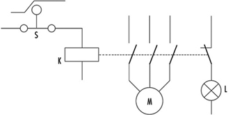
This channel uses switch S with positive action. The contactor K is supervised by the light L. The operator is advised that the normally open (NO) contacts stick by means of indication light L. The contactor K has forced guided contacts. (Note: Relays or contactors with forced guidance of contacts have, in comparison with usual relays or contactors, a special cage made from insulating material so that if normally closed (NC) contacts are closed, all NO contacts have to be opened, and vice versa. This means that by use of NC contacts a check may be made to determine that the working contacts are not sticking or welded together.)
Category 2
Category 2 provides for automatic detection of failures. Automatic failure detection has to be generated before each dangerous movement. Only if the test is positive may the movement be performed; otherwise the machine will be stopped. Automatic failure detection systems are used for light barriers to prove that they are still working. The principle is illustrated in figure 1.
Figure 11. Circuit including a failure detector
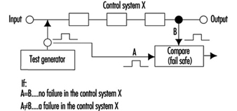
This control system is tested regularly (or occasionally) by injecting an impulse to the input. In a properly working system this impulse will then be transferred to the output and compared to an impulse from a test generator. When both impulses are present, the system obviously works. Otherwise, if there is no output impulse, the system has failed.
Category 3
Circuitry has been previously described under Example 3 in the Safety section of this article, figure 8.
The requirement—that is, automatic failure detection and the ability to perform the safety function even if one failure has occurred anywhere—can be fulfilled by two-channel control structures and by mutual supervising of the two channels.
For machine controls only, the dangerous failures have to be investigated. It should be noted that there are two kinds of failure:
- Non-dangerous failures are those that, after their occurrence, cause a “safe state” of the machine by providing for switching off the motor.
- Dangerous failures are those that, after their occurrence, cause an “unsafe state” of the machine, as the motor cannot be switched off or the motor starts to move unexpectedly.
Category 4
Category 4 typically provides for the application of a dynamic, continuously changing signal on the input. The presence of a dynamic signal on the output means running (“1”), and the absence of a dynamic signal means stop (“0”).
For such circuitry it is typical that after failure of any component the dynamic signal will no longer be available on the output. (Note: The static potential on the output is irrelevant.) Such circuits may be called “fail-safe”. All failures will be disclosed immediately, not after the first change (as in Category 3 circuits).
Further comments on control categories
Table 1 has been developed for usual machine controls and shows the basic circuit structures only; according to the machine directive it should be calculated on the assumption that only one failure will occur in one machine cycle. This is why the safety function does not have to be performed in the case of two coincident failures. It is assumed that a failure will be detected within one machine cycle. The machine will be stopped and then repaired. The control system then starts again, fully operable, without failures.
The first intent of the designer should be not to permit “standing” failures, which would not be detected during one cycle as they might later be combined with newly occurring failure(s) (failure cumulation). Such combinations (a standing failure and a new failure) can cause a malfunction of even Category 3 circuitry.
In spite of these tactics, it is possible that two independent failures will occur at the same time within the same machine cycle. It is only very improbable, especially if highly reliable components have been used. For very high-risk applications, three or more subchannels should be used. This philosophy is based on the fact that the mean time between failures is much longer than the machine cycle.
This does not mean, however, that the table cannot be further expanded. Table 1 is basically and structurally very similar to the Table 2 used in EN 954-1. However, it does not try to include too many sorting criteria. The requirements are defined according to the rigorous laws of logic, so that only clear answers (YES or NO) can be expected. This allows a more exact assessment, sorting and classification of submitted circuitry (safety-related channels) and, last but not least, significant improvement of assessment reproducibility.
It would be ideal if risks could be classified in various risk levels and then a definite link established between risk levels and categories, with this all independent of the technology in use. However, this is not fully possible. Early after creating categories it became clear that even given the same technology, various questions were not sufficiently answered. Which is better: a very reliable and well-designed component of Category 1, or a system fulfilling the requirements of Category 3 with poor reliability?
To explain this dilemma one must differentiate between two qualities: reliability and safety (against failures). They are not comparable, as both these qualities have different features:
- The component with highest reliability has the unpleasant feature that in the event of failure (even if highly improbable) the function will cease to perform.
- Category 3 systems, where even in case of one failure the function will be performed, are not safe against two failures at the same time (what may be important is whether sufficiently reliable components have been used).
Considering the above, it may be that the best solution (from the high-risk point of view) is to use highly reliable components and configure them so that the circuitry is safe against at least one failure (preferably more). It is clear that such a solution is not the most economical. In practice, the optimization process is mostly the consequence of all these influences and considerations.
Experience with practical use of the categories shows that it is rarely possible to design a control system that can utilize only one category throughout. Combination of two or even three parts, each of a different category, is typical, as illustrated in the following example:
Many safety light barriers are designed in Category 4, wherein one channel works with a dynamic signal. At the end of this system there usually are two mutually supervised subchannels which work with static signals. (This fulfils the requirements for Category 3.)
According to EN 50100, such light barriers are classified as Type 4 electro-sensitive protective devices, although they are composed of two parts. Unfortunately, there is no agreement how to denominate control systems consisting of two or more parts, each part of another category.
Programmable Electronic Systems (PESs)
The principles used to create table 1 can, with certain restrictions of course, be generally appled to PESs too.
PES-only system
In using PESs for control, the information is transferred from the sensor to the activator through a large number of components. Beyond that, it even passes “through” software. (See figure 12).
Figure 12. A PES system circuit
Although modern PESs are very reliable, the reliability is not as high as may be required for processing safety functions. Beyond that, the usual PES systems are not safe enough, since they will not perform the safety-related function in case of a failure. Therefore, using PESs for processing of safety functions without any additional measures is not permitted.
Very low-risk applications: Systems with one PES and additional measures
When using a single PES for control, the system consists of the following primary parts:
Input part
The reliability of a sensor and input of a PES can be improved by doubling them. Such a double-system input configuration can be further supervised by software to check if both subsystems are delivering the same information. Thus the failures in the input part can be detected. This is nearly the same philosophy as required for Category 3. However, because the supervising is done by software and only once, this may be denominated as 3- (or not as reliable as 3).
Middle part
Although this part cannot be well doubled, it can be tested. Upon switching on (or during operation), a check of the entire instruction set can be performed. At the same intervals, the memory can also be checked by suitable bit patterns. If such checks are conducted without failure, both parts, CPU and memory, are obviously working properly. The middle part has certain features typical of Category 4 (dynamic signal) and others typical of Category 2 (testing performed regularly at suitable intervals). The problem is that these tests, in spite of their extensiveness, cannot be really complete, as the one-PES system inherently does not allow them.
Output part
Similar to an input, the output (including activators) can also be doubled. Both subsystems can be supervised with respect to the same result. Failures will be detected and the safety function will be performed. However, there are the same weak points as in the input part. Consequently, Category 3 is chosen in this case.
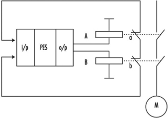
In figure 13 the same function is brought to relays A and B. The control contacts a and b, then informs two input systems whether both relays are doing the same work (unless a failure in one of the channels has occurred). Supervising is done again by software.
Figure 13. A PES circuit with a failure-detection system

The whole system can be described as Category 3-/4/2/3- if properly and extensively done. Nevertheless, the weak points of such systems as above described cannot be fully eliminated. In fact, improved one PESs are actually used for safety-related functions only where the risks are rather low (Hölscher and Rader 1984).
Low- and medium-risk applications with one PES
Today almost every machine is equipped with a PES control unit. To solve the problem of insufficient reliability and usually insufficient safety against failure, the following design methods are commonly used:
- In relatively simple machines such as lifts, the functions are divided into two groups: (1) the functions that are not related to safety are processed by the PES; (2) the safety-related functions are combined in one chain (safety circuit) and processed outside of the PES (see figure 14).
Figure 14. State of the art for stop category 0

- The method given above is not suitable for more complex machines. One reason is that such solutions usually are not safe enough. For medium-risk applications, solutions should fulfil the requirements for category 3. General ideas of how such designs may look are presented in figure 15 and figure 16.
Figure 15. State of the art for stop category 1
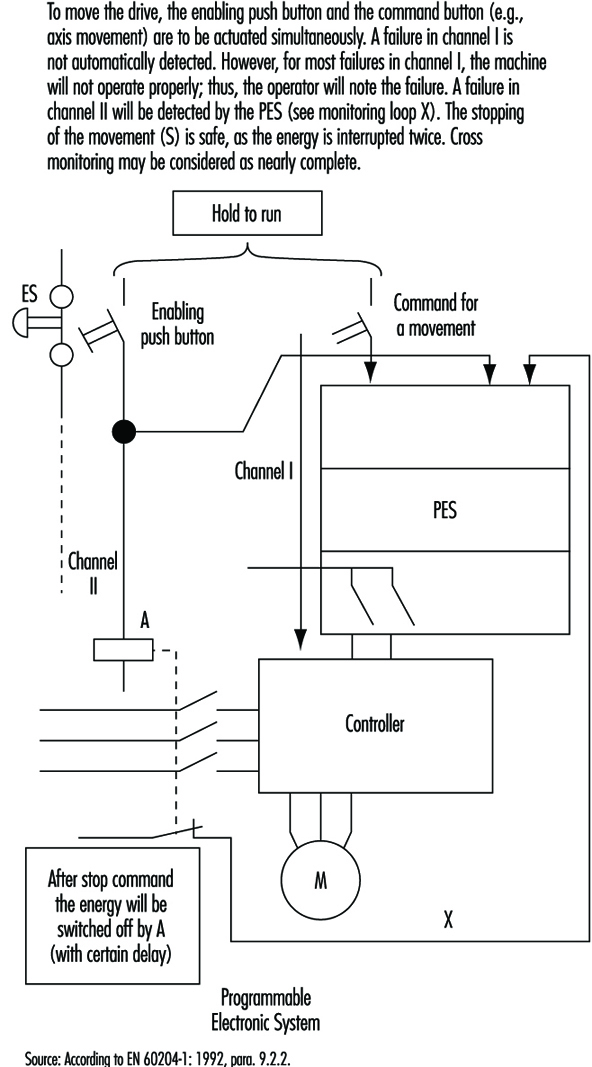
Figure 16. State of the art for stop category 2
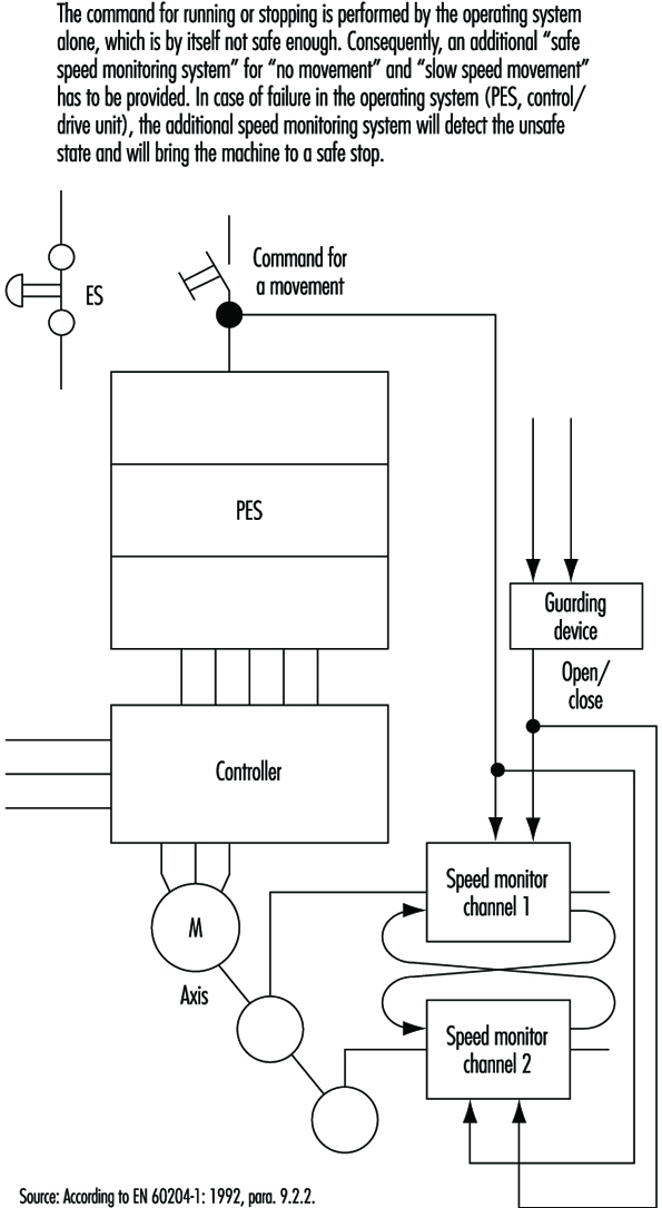
High-risk applications: systems with two (or more) PESs
Aside from complexity and expense, there are no other factors that would prevent designers from using fully doubled PES systems such as Siemens Simatic S5-115F, 3B6 Typ CAR-MIL and so on. These typically include two identical PESs with homogenous software, and assume the use of “well-tried” PESs and “well-tried” compilers (a well-tried PES or compiler can be considered one that in many practical applications over 3 or more years has shown that systematic failures have been obviously eliminated). Although these doubled PES systems do not have the weak points of single-PES systems, it does not mean that doubled PES systems solve all problems. (See figure 17).
Figure 17. Sophisticated system with two PESs
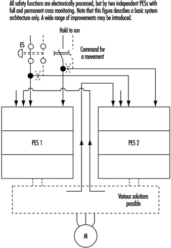
Systematic Failures
Systematic failures may result from errors in specifications, design and other causes, and may be present in hardware as well as in software. Double-PES systems are suitable for use in safety-related applications. Such configurations allow the detection of random hardware failures. By means of hardware diversity such as the use of two different types, or products of two different manufacturers, systematic hardware failures could be disclosed (it is highly unlikely that an identical hardware systematic failure would occur in both PES).
Software
Software is a new element in safety considerations. Software is either correct or incorrect (with respect to failures). Once correct, software cannot become instantly incorrect (as compared to hardware). The aims are to eradicate all errors in the software or to at least identify them.
There are various ways of achieving this goal. One is the verification of the program (a second person attempts to discover the errors in a subsequent test). Another possibility is diversity of the software, wherein two different programs, written by two programmers, address the same problem. If the results are identical (within certain limits), it can be assumed that both program sections are correct. If the results are different, it is presumed that errors are present. (N.B., The architecture of the hardware naturally must also be considered.)
Summary
When using PESs, generally the same following basic considerations are to be taken in account (as described in the previous sections).
- One control system without any redundancy may be allocated to Category B. One control system with additional measures may be Category 1 or even higher, but not higher than 2.
- A two-part control system with mutual comparison of results may be allocated to Category 3. A two-part control system with mutual comparison of results and more or less diversity may be allocated to Category 3 and is suitable for higher-risk applications.
A new factor is that for the system with a PES, even software should be evaluated from the correctness point of view. Software, if correct, is 100% reliable. At this stage of technological development, the best possible and known technical solutions will probably not be used, since the limiting factors are still economic. Furthermore, various groups of experts are continuing to develop the standards for safety applications of PESs (e.g., EC, EWICS). Although there are various standards already available (VDE0801, IEC65A and so on), this matter is so broad and complex that none of them may be considered as final.
Lathes
Adapted from the 3rd edition, Encyclopaedia of Occupational Health and Safety.
The important part lathes play in metalworking shops is best illustrated by the fact that 90 to 95% of the swarf (metal shavings) produced in the valves and fittings industry originates from lathes. About one-tenth of the accidents reported in this industry are due to lathes; this corresponds to one-third of all machine accidents. According to a study of the relative accident frequency per machine unit carried out in a plant manufacturing small precision parts and electrical equipment, lathes rank fifth after woodworking machines, metal-cutting saws, power presses and drilling machines. The need for protective measures on lathes is therefore beyond doubt.
Turning is a machine process in which the diameter of material is reduced by a tool with a special cutting edge. The cutting movement is produced by rotating the workpiece, and the feed and traverse movements are produced by the tool. By varying these three basic movements, and also by choosing the appropriate tool cutting-edge geometry and material, it is possible to influence the rate of stock removal, surface quality, shape of the chip formed and tool wear.
Structure of Lathes
A typical lathe consists of:
- a bed or base with machined slideways for the saddle and tailstock
- a headstock mounted on the bed, with the spindle and chuck
- a feed gearbox attached to the front of the bed for transmitting the feed movement as a function of the cutting speed through the leadscrew or feed shaft and apron to the saddle
- a saddle (or carriage) carrying the cross slide which performs the traverse movement
- a toolpost mounted on the cross slide (see figure 1).
Figure 1. Lathes and similar machines
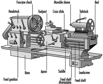
This basic model of a lathe can be infinitely varied, from the universal machine to the special automatic lathe designed for one type of work only.
The most important types of lathe are as follows:
- Centre lathe. This is the most frequently used turning machine. It corresponds to the basic model with horizontal turning axis. The work is held between centres, by a faceplate or in a chuck.
- Multiple-tool lathe. This enables several tools to be engaged at the same time.
- Turret lathe, capstan lathe. Machines of this type enable a workpiece to be machined by several tools which are engaged one after the other. The tools are held in the turret, which rotates for bringing them into cutting position. The turrets are generally of the disc or crown type, but there are also drum-type turret lathes.
- Copy-turning lathes. The desired shape is transmitted by tracer control from a template to the work.
- Automatic lathe. The various operations, including the change of the work, are automated. There are bar automatics and chucking automatics.
- Vertical lathe (boring and turning mill). The work turns about a vertical axis; it is clamped to a horizontal revolving table. This type of machine is generally used for machining large castings and forgings.
- NC and CNC lathes. All the aforementioned machines can be equipped with a numerical control (NC) or computer-assisted numerical control (CNC) system. The result is a semi-automated or fully automated machine which can be used rather universally, thanks to the great versatility and easy programmability of the control system.
The future development of the lathe will probably concentrate on control systems. Contact controls will be increasingly replaced by electronic control systems. As regards the latter, there is a trend in evolution from interpolation-programmed to memory-programmed controls. It is foreseeable in the long run that the use of increasingly efficient process computers will tend to optimize the machining process.
Accidents
Lathe accidents are generally caused by:
- disregard for safety regulations when the machines are installed in workshops (e.g., not enough space between machines, no power disconnect switch for each machine)
- missing guards or the absence of auxiliary devices (severe injuries have been caused to workers who tried to brake the spindle of their lathes by pressing one of their hands against unguarded belt pulleys and to operators who inadvertently engaged unguarded clutch levers or pedals; injuries due to flying chips because of the absence of hinged or sliding covers have also occurred)
- inadequately located control elements (e.g., a turner’s hand can be pierced by the tailstock centre if the pedal controlling the chuck is mistaken for the one controlling the hydraulic circuit of the tailstock centre movement)
- adverse conditions of work (i.e., shortcomings from the point of view of occupational physiology)
- lack of PPE or wearing unsuitable work clothing (severe and even fatal injuries have been caused to lathe operators who wore loose clothes or had long, free-hanging hair)
- insufficient instruction of personnel (an apprentice was fatally injured when he filed a short shaft which was fixed between centres and rotated by a cranked carrier on the spindle nose and a straight one on the shaft; the lathe carrier seized his left-hand sleeve, which was wrapped around the workpiece, dragging the apprentice violently into the lathe)
- poor work organization leading to the use of unsuitable equipment (e.g., a long bar was machined on a conventional production lathe; it was too long for this lathe, and it projected more than 1 m beyond the headstock; moreover, the chuck aperture was too large for the bar and was made up by inserting wooden wedges; when the lathe spindle started rotating, the free bar end bent by 45° and struck the operator’s head; the operator died during the following night)
- defective machine elements (e.g., a loose carrier pin in a clutch may cause the lathe spindle to start rotating while the operator is adjusting a workpiece in the chuck).
Accident Prevention
The prevention of lathe accidents starts at the design stage. Designers should give special attention to control and transmission elements.
Control elements
Each lathe must be equipped with a power disconnect (or isolating) switch so that maintenance and repair work may be carried out safely. This switch must disconnect the current on all poles, reliably cut the pneumatic and hydraulic power and vent the circuits. On large machines, the disconnect switch should be so designed that it can be padlocked in its out position—a safety measure against accidental reconnection.
The layout of the machine controls should be such that the operator can easily distinguish and reach them, and that their manipulation presents no hazard. This means that controls must never be arranged at points which can be reached only by passing the hand over the working zone of the machine or where they may be hit by flying chips.
Switches which monitor guards and interlock them with the machine drive should be chosen and installed in such a way that they positively open the circuit as soon as the guard is shifted from its protecting position.
Emergency stop devices must cause the immediate standstill of the dangerous movement. They must be designed and located in such a way that they can be easily operated by the threatened worker. Emergency stop buttons must be easily reached and should be in red.
The actuating elements of control gear which may trip a dangerous machine movement must be guarded so as to exclude any inadvertent operation. For instance, the clutch engaging levers on the headstock and apron should be provided with safety locking devices or screens. A push-button can be made safe by lodging it in a recess or by shrouding it with a protective collar.
Hand-operated controls should be designed and located in such a way that the hand movement corresponds to the controlled machine movement.
Controls should be identified with easily readable and understandable markings. To avoid misunderstandings and linguistic difficulties, it is advisable to use symbols.
Transmission elements
All moving transmission elements (belts, pulleys, gears) must be covered with guards. An important contribution to the prevention of lathe accidents can be made by the persons responsible for the installation of the machine. Lathes should be so installed that the operators tending them do not hinder or endanger each other. The operators should not turn their backs towards passageways. Protective screens should be installed where neighbouring workplaces or passageways are within the range of flying chips.
Passageways must be clearly marked. Enough space should be left for materials-handling equipment, for stacking workpieces and for tool boxes. Bar-stock guides must not protrude into the passageways.
The floor on which the operator stands must be insulated against cold. Care should be taken that the insulation forms no stumbling obstacle, and the flooring should not become slippery even when covered with a film of oil.
Conduit and pipework should be installed in such a way that they do not become obstacles. Temporary installations should be avoided.
Safety engineering measures on the shop floor should be directed in particular at the following points:
- work-holding fixtures (faceplates, chucks, collets) should be dynamically balanced before use
- the maximum permissible speed of a chuck should be indicated on the chuck by the manufacturer and respected by the lathe operator
- when scroll chucks are used, it should be ensured that the jaws cannot be slung out when the lathe is started
- chucks of this type should be designed in such a manner that the key cannot be taken off before the jaws have been secured. The chuck keys in general should be so designed that it is impossible to leave them in the chuck.
It is important to provide for auxiliary lifting equipment to facilitate mounting and removing of heavy chucks and faceplates. To prevent chucks from running off the spindle when the lathe is suddenly braked, they must be securely fixed. This can be achieved by putting a retaining nut with left-hand thread on the spindle nose, by using a “Camlock” quick-action coupling, by fitting the chuck with a locking key or by securing it with a two-part locking ring.
When powered work-holding fixtures are used, such as hydraulically operated chucks, collets and tailstock centres, measures must be taken which make it impossible for the hands to be introduced into the danger zone of closing fixtures. This can be achieved by limiting the travel of the clamping element to 6 mm, by choosing the location of deadman’s controls so as to exclude the introduction of the hands into the danger zone or by providing a moving guard which has to be closed before the clamping movement can be started.
If starting the lathe while the chuck jaws are open presents a danger, the machine should be equipped with a device which prevents the spindle rotation being started before the jaws are closed. The absence of power must not cause the opening or closure of a powered work-holding fixture.
If the gripping force of a power chuck diminishes, the spindle rotation must be stopped, and it must be impossible to start the spindle. Reversing the gripping direction from inside to outside (or vice versa) while the spindle rotates must not cause the chuck to be dislodged from the spindle. Removal of holding fixtures from the spindle should be possible only when the spindle has ceased rotating.
When machining bar stock, the portion projecting beyond the lathe must be enclosed by bar-stock guides. Bar feed weights must be guarded by hinged covers extending to the floor.
Carriers
To prevent serious accidents—in particular, when filing work in a lathe—unprotected carriers must not be used. A centring safety carrier should be used, or a protective collar should be fitted to a conventional carrier. It is also possible to use self-locking carriers or to provide the carrier disc with a protective cover.
Working zone of the lathe
Universal-lathe chucks should be guarded by hinged covers. If possible, protective covers should be interlocked with spindle drive circuits. Vertical boring and turning mills should be fenced with bars or plates to prevent injury from revolving parts. To enable the operator to watch the machining process safely, platforms with railings must be provided. In certain cases, TV cameras can be installed so that the operator may monitor the tool edge and tool in-feed.
The working zones of automatic lathes, NC and CNC lathes should be completely enclosed. Enclosures of fully automatic machines should only have openings through which the stock to be machined is introduced, the turned part ejected and the swarf removed from the working zone. These openings must not constitute a hazard when work passes through them, and it must be impossible to reach through them into the danger zone.
The working zones of semi-automatic, NC and CNC lathes must be enclosed during the machining process. The enclosures are generally sliding covers with limit switches and interlocking circuit.
Operations requiring access to the working zone, such as change of work or tools, gauging and so on, must not be carried out before the lathe has been safely stopped. Zeroing a variable-speed drive is not considered a safe standstill. Machines with such drives must have locked protective covers that cannot be unlocked before the machine is safely stopped (e.g., by cutting the spindle-motor power supply).
If special tool-setting operations are required, an inching control is to be provided which enables certain machine movements to be tripped while the protective cover is open. In such cases, the operator can be protected by special circuit designs (e.g., by permitting only one movement to be tripped at a time). This can be achieved by using two-hand controls.
Turning swarf
Long turning chips are dangerous because they may get entangled with arms and legs and cause serious injury. Continuous and ravelled chips can be avoided by choosing appropriate cutting speeds, feeds and chip thicknesses or by using lathe tools with chip breakers of the gullet or step type. Swarf hooks with handle and buckle should be used for removing chips.
Ergonomics
Every machine should be so designed that it enables a maximal output to be obtained with a minimum of stress on the operator. This can be achieved by adapting the machine to the worker.
Ergonomic factors must be taken into account when designing the human-machine interface of a lathe. Rational workplace design also includes providing for auxiliary handling equipment, such as loading and unloading attachments.
All controls must be located within the physiological sphere or reach of both hands. The controls must be clearly laid out and should be logical to operate. Pedal-operated controls should be avoided in machines tended by standing operators.
Experience has shown that good work is performed when the workplace is designed for both standing and sitting postures. If the operator has to work standing up, he or she should be given the possibility of changing posture. Flexible seats are in many cases a welcome relief for strained feet and legs.
Measures should be taken to create optimal thermal comfort, taking into account the air temperature, relative humidity, air movement and radiant heat. The workshop should be adequately ventilated. There should be local exhaust devices to eliminate gaseous emanations. When machining bar stock, sound-absorbent-lined guide tubes should be used.
The workplace should preferably be provided with uniform lighting, affording an adequate level of illumination.
Work Clothing and Personal Protection
Overalls should be close fitting and buttoned or zipped to the neck. They should be without breast pockets, and the sleeves must be tightly buttoned at the wrists. Belts should not be worn. No finger rings and bracelets should be worn when working on lathes. Wearing of safety spectacles should be obligatory. When heavy workpieces are machined, safety shoes with steel toe caps must be worn. Protective gloves must be worn whenever swarf is being collected.
Training
The lathe operator’s safety depends to a large extent on working methods. It is therefore important that he or she should receive thorough theoretical and practical training to acquire skills and develop a behaviour affording the best possible safeguards. Correct posture, correct movements, correct choice and handling of tools should become routine to such an extent that the operator works correctly even if his or her concentration is temporarily relaxed.
Important points in a training programme are an upright posture, the proper mounting and removal of the chuck and the accurate and secure fixing of workpieces. Correct holding of files and scrapers and safe working with abrasive cloth must be intensively practised.
Workers must be well informed about the hazards of injury which may be caused when gauging work, checking adjustments and cleaning lathes.
Maintenance
Lathes must be regularly maintained and lubricated. Faults must be corrected immediately. If safety is at stake in the event of a fault, the machine should be put out of operation until corrective action has been taken.
Repair and maintenance work must be carried out only after the machine has been isolated from the power supply
.
" DISCLAIMER: The ILO does not take responsibility for content presented on this web portal that is presented in any language other than English, which is the language used for the initial production and peer-review of original content. Certain statistics have not been updated since the production of the 4th edition of the Encyclopaedia (1998)."