- You are here:
-
Home

-
Part VI. General Hazards
- Lighting

46. Lighting
Chapter Editor: Juan Guasch Farrás
Table of Contents
Figures and Tables
Types of Lamps and Lighting
Richard Forster
Conditions Required for Visual
Fernando Ramos Pérez and Ana Hernández Calleja
General Lighting Conditions
N. Alan Smith
Tables
Click a link below to view table in article context.
1. Improved output & wattage of some 1,500 mm fluorescent tube lamps
2. Typical lamp efficacies
3. International Lamp Coding System (ILCOS) for some lamp types
4. Common colours & shapes of incandescent lamps & ILCOS codes
5. Types of high-pressure sodium lamp
6. Colour contrasts
7. Reflection factors of different colours & materials
8. Recommended levels of maintained illuminance for locations/tasks
Figures
Point to a thumbnail to see figure caption, click to see figure in article context.
|
|


Types of Lamps and Lighting
A lamp is an energy converter. Although it may carry out secondary functions, its prime purpose is the transformation of electrical energy into visible electromagnetic radiation. There are many ways to create light. The standard method for creating general lighting is the conversion of electrical energy into light.
Types of Light
Incandescence
When solids and liquids are heated, they emit visible radiation at temperatures above 1,000 K; this is known as incandescence.
Such heating is the basis of light generation in filament lamps: an electrical current passes through a thin tungsten wire, whose temperature rises to around 2,500 to 3,200 K, depending upon the type of lamp and its application.
There is a limit to this method, which is described by Planck’s Law for the performance of a black body radiator, according to which the spectral distribution of energy radiated increases with temperature. At about 3,600 K and above, there is a marked gain in emission of visible radiation, and the wavelength of maximum power shifts into the visible band. This temperature is close to the melting point of tungsten, which is used for the filament, so the practical temperature limit is around 2,700 K, above which filament evaporation becomes excessive. One result of these spectral shifts is that a large part of the radiation emitted is not given off as light but as heat in the infrared region. Filament lamps can thus be effective heating devices and are used in lamps designed for print drying, food preparation and animal rearing.
Electric discharge
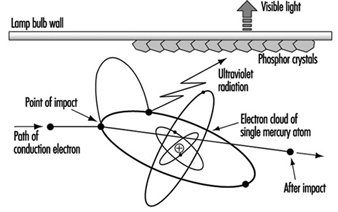
Electrical discharge is a technique used in modern light sources for commerce and industry because of the more efficient production of light. Some lamp types combine the electrical discharge with photoluminescence.
An electric current passed through a gas will excite the atoms and molecules to emit radiation of a spectrum which is characteristic of the elements present. Two metals are commonly used, sodium and mercury, because their characteristics give useful radiations within the visible spectrum. Neither metal emits a continuous spectrum, and discharge lamps have selective spectra. Their colour rendering will never be identical to continuous spectra. Discharge lamps are often classed as high pressure or low pressure, although these terms are only relative, and a high-pressure sodium lamp operates at below one atmosphere.
Types of Luminescence
Photoluminescence occurs when radiation is absorbed by a solid and is then re-emitted at a different wavelength. When the re-emitted radiation is within the visible spectrum the process is called fluorescence or phosphorescence.
Electroluminescence occurs when light is generated by an electric current passed through certain solids, such as phosphor materials. It is used for self-illuminated signs and instrument panels but has not proved to be a practical light source for the lighting of buildings or exteriors.
Evolution of Electric Lamps
Although technological progress has enabled different lamps to be produced, the main factors influencing their development have been external market forces. For example, the production of filament lamps in use at the start of this century was possible only after the availability of good vacuum pumps and the drawing of tungsten wire. However, it was the large-scale generation and distribution of electricity to meet the demand for electric lighting that determined market growth. Electric lighting offered many advantages over gas- or oil-generated light, such as steady light that requires infrequent maintenance as well as the increased safety of having no exposed flame, and no local by-products of combustion.
During the period of recovery after the Second World War, the emphasis was on productivity. The fluorescent tubular lamp became the dominant light source because it made possible the shadow-free and comparatively heat-free lighting of factories and offices, allowing maximum use of the space. The light output and wattage requirements for a typical 1,500 mm fluorescent tubular lamp is given in table 1.
Table 1. Improved light output and wattage requirements of some typical 1,500 mm fluorescent tube lamps
|
Rating (W) |
Diameter (mm) |
Gas fill |
Light output (lumens) |
|
80 |
38 |
argon |
4,800 |
|
65 |
38 |
argon |
4,900 |
|
58 |
25 |
krypton |
5,100 |
|
50 |
25 |
argon |
5,100 |
By the 1970s oil prices rose and energy costs became a significant part of operating costs. Fluorescent lamps that produce the same amount of light with less electrical consumption were demanded by the market. Lamp design was refined in several ways. As the century closes there is a growing awareness of global environment issues. Better use of declining raw materials, recycling or safe disposal of products and the continuing concern over energy consumption (particularly energy generated from fossil fuels) are impacting on current lamp designs.
Performance Criteria
Performance criteria vary by application. In general, there is no particular hierarchy of importance of these criteria.
Light output: The lumen output of a lamp will determine its suitability in relation to the scale of the installation and the quantity of illumination required.
Colour appearance and colour rendering: Separate scales and numerical values apply to colour appearance and colour rendering. It is important to remember that the figures provide guidance only, and some are only approximations. Whenever possible, assessments of suitability should be made with actual lamps and with the colours or materials that apply to the situation.
Lamp life: Most lamps will require replacement several times during the life of the lighting installation, and designers should minimize the inconvenience to the occupants of odd failures and maintenance. Lamps are used in a wide variety of applications. The anticipated average life is often a compromise between cost and performance. For example, the lamp for a slide projector will have a life of a few hundred hours because the maximum light output is important to the quality of the image. By contrast, some roadway lighting lamps may be changed every two years, and this represents some 8,000 burning hours.
Further, lamp life is affected by operating conditions, and thus there is no simple figure that will apply in all conditions. Also, the effective lamp life may be determined by different failure modes. Physical failure such as filament or lamp rupture may be preceded by reduction in light output or changes in colour appearance. Lamp life is affected by external environmental conditions such as temperature, vibration, frequency of starting, supply voltage fluctuations, orientation and so on.
It should be noted that the average life quoted for a lamp type is the time for 50% failures from a batch of test lamps. This definition of life is not likely to be applicable to many commercial or industrial installations; thus practical lamp life is usually less than published values, which should be used for comparison only.
Efficiency: As a general rule the efficiency of a given type of lamp improves as the power rating increases, because most lamps have some fixed loss. However, different types of lamps have marked variation in efficiency. Lamps of the highest efficiency should be used, provided that the criteria of size, colour and lifetime are also met. Energy savings should not be at the expense of the visual comfort or the performance ability of the occupants. Some typical efficacies are given in table 2.
Table 2. Typical lamp efficacies
|
Lamp efficacies |
|
|
100 W filament lamp |
14 lumens/watt |
|
58 W fluorescent tube |
89 lumens/watt |
|
400 W high-pressure sodium |
125 lumens/watt |
|
131 W low-pressure sodium |
198 lumens/watt |
Main lamp types
Over the years, several nomenclature systems have been developed by national and international standards and registers.
In 1993, the International Electrotechnical Commission (IEC) published a new International Lamp Coding System (ILCOS) intended to replace existing national and regional coding systems. A list of some ILCOS short form codes for various lamps is given in table 3.
Table 3. International Lamp Coding System (ILCOS) short form coding system for some lamp types
|
Type (code) |
Common ratings (watts) |
Colour rendering |
Colour temperature (K) |
Life (hours) |
|
Compact fluorescent lamps (FS) |
5–55 |
good |
2,700–5,000 |
5,000–10,000 |
|
High-pressure mercury lamps (QE) |
80–750 |
fair |
3,300–3,800 |
20,000 |
|
High-pressure sodium lamps (S-) |
50–1,000 |
poor to good |
2,000–2,500 |
6,000–24,000 |
|
Incandescent lamps (I) |
5–500 |
good |
2,700 |
1,000–3,000 |
|
Induction lamps (XF) |
23–85 |
good |
3,000–4,000 |
10,000–60,000 |
|
Low-pressure sodium lamps (LS) |
26–180 |
monochromatic yellow colour |
1,800 |
16,000 |
|
Low-voltage tungsten halogen lamps (HS) |
12–100 |
good |
3,000 |
2,000–5,000 |
|
Metal halide lamps (M-) |
35–2,000 |
good to excellent |
3,000–5,000 |
6,000–20,000 |
|
Tubular fluorescent lamps (FD) |
4–100 |
fair to good |
2,700–6,500 |
10,000–15,000 |
|
Tungsten halogen lamps (HS) |
100–2,000 |
good |
3,000 |
2,000–4,000 |
Incandescent lamps
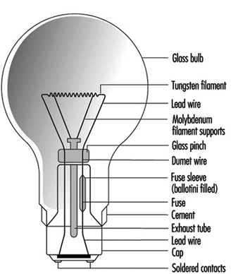
These lamps use a tungsten filament in an inert gas or vacuum with a glass envelope. The inert gas suppresses tungsten evaporation and lessens the envelope blackening. There is a large variety of lamp shapes, which are largely decorative in appearance. The construction of a typical General Lighting Service (GLS) lamp is given in figure 1.
Figure 1. Construction of a GLS lamp
Incandescent lamps are also available with a wide range of colours and finishes. The ILCOS codes and some typical shapes include those shown in table 4.
Table 4. Common colours and shapes of incandescent lamps, with their ILCOS codes
|
Colour/Shape |
Code |
|
Clear |
/C |
|
Frosted |
/F |
|
White |
/W |
|
Red |
/R |
|
Blue |
/B |
|
Green |
/G |
|
Yellow |
/Y |
|
Pear shaped (GLS) |
IA |
|
Candle |
IB |
|
Conical |
IC |
|
Globular |
IG |
|
Mushroom |
IM |
Incandescent lamps are still popular for domestic lighting because of their low cost and compact size. However, for commercial and industrial lighting the low efficacy generates very high operating costs, so discharge lamps are the normal choice. A 100 W lamp has a typical efficacy of 14 lumens/watt compared with 96 lumens/watt for a 36 W fluorescent lamp.
Incandescent lamps are simple to dim by reducing the supply voltage, and are still used where dimming is a desired control feature.
The tungsten filament is a compact light source, easily focused by reflectors or lenses. Incandescent lamps are useful for display lighting where directional control is needed.
Tungsten halogen lamps
These are similar to incandescent lamps and produce light in the same manner from a tungsten filament. However the bulb contains halogen gas (bromine or iodine) which is active in controlling tungsten evaporation. See figure 2.
Figure 2. The halogen cycle
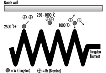
Fundamental to the halogen cycle is a minimum bulb wall temperature of 250 °C to ensure that the tungsten halide remains in a gaseous state and does not condense on the bulb wall. This temperature means bulbs made from quartz in place of glass. With quartz it is possible to reduce the bulb size.
Most tungsten halogen lamps have an improved life over incandescent equivalents and the filament is at a higher temperature, creating more light and whiter colour.
Tungsten halogen lamps have become popular where small size and high performance are the main requirement. Typical examples are stage lighting, including film and TV, where directional control and dimming are common requirements.
Low-voltage tungsten halogen lamps
These were originally designed for slide and film projectors. At 12 V the filament for the same wattage as 230 V becomes smaller and thicker. This can be more efficiently focused, and the larger filament mass allows a higher operating temperature, increasing light output. The thick filament is more robust. These benefits were realized as being useful for the commercial display market, and even though it is necessary to have a step-down transformer, these lamps now dominate shop-window lighting. See figure 3.
Figure 3. Low-voltage dichroic reflector lamp
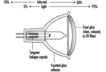
Although users of film projectors want as much light as possible, too much heat damages the transparency medium. A special type of reflector has been developed, which reflects only the visible radiation, allowing infrared radiation (heat) to pass through the back of lamp. This feature is now part of many low-voltage reflector lamps for display lighting as well as projector equipment.
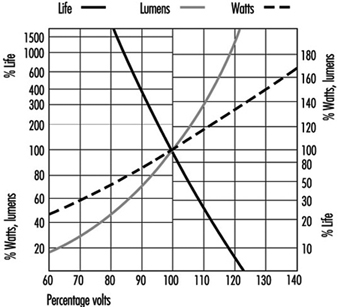
Voltage sensitivity: All filament lamps are sensitive to voltage variation, and light output and life are affected. The move to “harmonize” the supply voltage throughout Europe at 230 V is being achieved by widening the tolerances to which the generating authorities can operate. The move is towards ±10%, which is a voltage range of 207 to 253 V. Incandescent and tungsten halogen lamps cannot be operated sensibly over this range, so it will be necessary to match actual supply voltage to lamp ratings. See figure 4.
Figure 4. GLS filament lamps and supply voltage
Discharge lamps will also be affected by this wide voltage variation, so the correct specification of control gear becomes important.
Tubular fluorescent lamps
These are low pressure mercury lamps and are available as “hot cathode” and “cold cathode” versions. The former is the conventional fluorescent tube for offices and factories; “hot cathode” relates to the starting of the lamp by pre-heating the electrodes to create sufficient ionization of the gas and mercury vapour to establish the discharge.
Cold cathode lamps are mainly used for signage and advertising. See figure 5.
Figure 5. Principle of fluorescent lamp
Fluorescent lamps require external control gear for starting and to control the lamp current. In addition to the small amount of mercury vapour, there is a starting gas (argon or krypton).
The low pressure of mercury generates a discharge of pale blue light. The major part of the radiation is in the UV region at 254 nm, a characteristic radiation frequency for mercury. Inside of the tube wall is a thin phosphor coating, which absorbs the UV and radiates the energy as visible light. The colour quality of the light is determined by the phosphor coating. A range of phosphors are available of varying colour appearance and colour rendering.
During the 1950s phosphors available offered a choice of reasonable efficacy (60 lumens/watt) with light deficient in reds and blues, or improved colour rendering from “deluxe” phosphors of lower efficiency (40 lumens/watt).
By the 1970s new, narrow-band phosphors had been developed. These separately radiated red, blue and green light but, combined, produced white light. Adjusting the proportions gave a range of different colour appearances, all with similar excellent colour rendering. These tri-phosphors are more efficient than the earlier types and represent the best economic lighting solution, even though the lamps are more expensive. Improved efficacy reduces operating and installation costs.
The tri-phosphor principle has been extended by multi-phosphor lamps where critical colour rendering is necessary, such as for art galleries and industrial colour matching.
The modern narrow-band phosphors are more durable, have better lumen maintenance, and increase lamp life.
Compact fluorescent lamps
The fluorescent tube is not a practical replacement for the incandescent lamp because of its linear shape. Small, narrow-bore tubes can be configured to approximately the same size as the incandescent lamp, but this imposes a much higher electrical loading on the phosphor material. The use of tri-phosphors is essential to achieve acceptable lamp life. See figure 6.
Figure 6. Four-leg compact fluorescent

All compact fluorescent lamps use tri-phosphors, so, when they are used together with linear fluorescent lamps, the latter should also be tri-phosphor to ensure colour consistency.
Some compact lamps include the operating control gear to form retro-fit devices for incandescent lamps. The range is increasing and enables easy upgrading of existing installations to more energy-efficient lighting. These integral units are not suitable for dimming where that was part of the original controls.
High-frequency electronic control gear: If the normal supply frequency of 50 or 60 Hz is increased to 30 kHz, there is a 10% gain in efficacy of fluorescent tubes. Electronic circuits can operate individual lamps at such frequencies. The electronic circuit is designed to provide the same light output as wire-wound control gear, from reduced lamp power. This offers compatibility of lumen package with the advantage that reduced lamp loading will increase lamp life significantly. Electronic control gear is capable of operating over a range of supply voltages.
There is no common standard for electronic control gear, and lamp performance may differ from the published information issued by the lamp makers.
The use of high-frequency electronic gear removes the normal problem of flicker, to which some occupants may be sensitive.
Induction lamps
Lamps using the principle of induction have recently appeared on the market. They are low-pressure mercury lamps with tri-phosphor coating and as light producers are similar to fluorescent lamps. The energy is transferred to the lamp by high-frequency radiation, at approximately 2.5 MHz from an antenna positioned centrally within the lamp. There is no physical connection between the lamp bulb and the coil. Without electrodes or other wire connections the construction of the discharge vessel is simpler and more durable. Lamp life is mainly determined by the reliability of the electronic components and the lumen maintenance of the phosphor coating.
High-pressure mercury lamps
High-pressure discharges are more compact and have higher electrical loads; therefore, they require quartz arc tubes to withstand the pressure and temperature. The arc tube is contained in an outer glass envelope with a nitrogen or argon-nitrogen atmosphere to reduce oxidation and arcing. The bulb effectively filters the UV radiation from the arc tube. See figure 7.
Figure 7. Mercury lamp construction
At high pressure, the mercury discharge is mainly blue and green radiation. To improve the colour a phosphor coating of the outer bulb adds red light. There are deluxe versions with an increased red content, which give higher light output and improved colour rendering.
All high-pressure discharge lamps take time to reach full output. The initial discharge is via the conducting gas fill, and the metal evaporates as the lamp temperature increases.
At the stable pressure the lamp will not immediately restart without special control gear. There is a delay while the lamp cools sufficiently and the pressure reduces, so that the normal supply voltage or ignitor circuit is adequate to re-establish the arc.
Discharge lamps have a negative resistance characteristic, and so the external control gear is necessary to control the current. There are losses due to these control gear components so the user should consider total watts when considering operating costs and electrical installation. There is an exception for high-pressure mercury lamps, and one type contains a tungsten filament which both acts as the current limiting device and adds warm colours to the blue/green discharge. This enables the direct replacement of incandescent lamps.
Although mercury lamps have a long life of about 20,000 hours, the light output will fall to about 55% of the initial output at the end of this period, and therefore the economic life can be shorter.
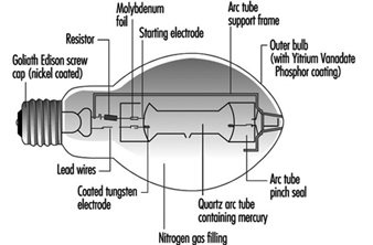
Metal halide lamps
The colour and light output of mercury discharge lamps can be improved by adding different metals to the mercury arc. For each lamp the dose is small, and for accurate application it is more convenient to handle the metals in powder form as halides. This breaks down as the lamp warms up and releases the metal.
A metal halide lamp can use a number of different metals, each of which give off a specific characteristic colour. These include:
- dysprosium—broad blue-green
- indium—narrow blue
- lithium—narrow red
- scandium—broad blue-green
- sodium—narrow yellow
- thallium—narrow green
- tin—broad orange-red
There is no standard mixture of metals, so metal halide lamps from different manufacturers may not be compatible in appearance or operating performance. For lamps with the lower wattage ratings, 35 to 150 W, there is closer physical and electrical compatibility with a common standard.
Metal halide lamps require control gear, but the lack of compatibility means that it is necessary to match each combination of lamp and gear to ensure correct starting and running conditions.
Low-pressure sodium lamps
The arc tube is similar in size to the fluorescent tube but is made of special ply glass with an inner sodium resistant coating. The arc tube is formed in a narrow “U” shape and is contained in an outer vacuum jacket to ensure thermal stability. During starting, the lamps have a strong red glow from the neon gas fill.
The characteristic radiation from low-pressure sodium vapour is a monochromatic yellow. This is close to the peak sensitivity of the human eye, and low-pressure sodium lamps are the most efficient lamps available at nearly 200 lumens/watt. However the applications are limited to where colour discrimination is of no visual importance, such as trunk roads and underpasses, and residential streets.
In many situations these lamps are being replaced by high-pressure sodium lamps. Their smaller size offers better optical control, particularly for roadway lighting where there is growing concern over excessive sky glow.
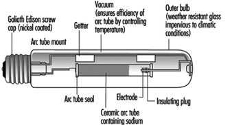
High-pressure sodium lamps
These lamps are similar to high-pressure mercury lamps but offer better efficacy (over 100 lumens/watt) and excellent lumen maintenance. The reactive nature of sodium requires the arc tube to be manufactured from translucent polycrystalline alumina, as glass or quartz are unsuitable. The outer glass bulb contains a vacuum to prevent arcing and oxidation. There is no UV radiation from the sodium discharge so phosphor coatings are of no value. Some bulbs are frosted or coated to diffuse the light source. See figure 8.
Figure 8. High-pressure sodium lamp construction
As the sodium pressure is increased, the radiation becomes a broad band around the yellow peak, and the appearance is golden white. However, as the pressure increases, the efficiency decreases. There are currently three separate types of high-pressure sodium lamps available, as shown in table 5.
Table 5. Types of high-pressure sodium lamp
|
Lamp type (code) |
Colour (K) |
Efficacy (lumens/watt) |
Life (hours) |
|
Standard |
2,000 |
110 |
24,000 |
|
Deluxe |
2,200 |
80 |
14,000 |
|
White (SON) |
2,500 |
50 |
Generally the standard lamps are used for exterior lighting, deluxe lamps for industrial interiors, and White SON for commercial/display applications.
Dimming of Discharge Lamps
The high-pressure lamps cannot be satisfactorily dimmed, as changing the lamp power changes the pressure and thus the fundamental characteristics of the lamp.
Fluorescent lamps can be dimmed using high-frequency supplies generated typically within the electronic control gear. The colour appearance remains very constant. In addition, the light output is approximately proportional to the lamp power, with consequent saving in electrical power when the light output is reduced. By integrating the light output from the lamp with the prevailing level of natural daylight, a near constant level of illuminance can be provided in an interior.
Conditions Required for Visual Comfort
Human beings possess an extraordinary capacity to adapt to their environment and to their immediate surroundings. Of all the types of energy that humans can utilize, light is the most important. Light is a key element in our capacity to see, and it is necessary to appreciate the form, the colour and the perspective of the objects that surround us in our daily lives. Most of the information we obtain through our senses we obtain through sight—close to 80%. Very often, and because we are so used to having it available, we take it for granted. We should not fail to keep in mind, however, that aspects of human welfare, like our state of mind or our level of fatigue, are affected by illumination and the colour of the things that surround us. From the point of view of safety at work, visual capacity and visual comfort are extraordinarily important. This is because many accidents are due to, among other reasons, illumination deficiencies or errors made by the worker because he or she finds it hard to identify objects or the risks associated with machinery, conveyances, dangerous containers and so on.
Visual disorders associated with deficiencies in the illumination system are common in the workplace. Due to the ability of sight to adapt to situations with deficient lighting, these aspects are sometimes not considered as seriously as they should be.
The correct design of an illumination system should offer the optimal conditions for visual comfort. For the attainment of this goal an early line of collaboration between architects, lighting designers and those responsible for hygiene at the worksite should be established. This collaboration should precede the beginning of the project, to avoid errors that would be difficult to correct once the project is completed. Among the most important aspects that should be kept in mind are the type of lamp that will be used and the lighting system that will be installed, the distribution of luminance, illumination efficiencies and the spectral composition of light.
The fact that light and colour affect the productivity and the psycho-physiological well-being of the worker should encourage the initiatives of illumination technicians, physiologists and ergonomists, to study and determine the most favourable conditions of light and colour at each work station. The combination of illumination, the contrast of luminances, the colour of light, the reproduction of colour or the selection of colours are the elements that determine colour climate and visual comfort.
Factors that Determine Visual Comfort
The prerequisites that an illumination system must fulfil in order to provide the conditions necessary for visual comfort are the following:
- uniform illumination
- optimal luminance
- no glare
- adequate contrast conditions
- correct colours
- absence of stroboscopic effect or intermittent light.
It is important to consider light in the workplace not only by quantitative criteria, but also by qualitative criteria. The first step is to study the work station, the precision required of the tasks performed, the amount of work, the mobility of the worker and so on. Light should include components both of diffuse and of direct radiation. The result of the combination will produce shadows of greater or lesser intensity that will allow the worker to perceive the form and position of objects at the work station. Annoying reflections, which make it harder to perceive details, should be eliminated, as well as excessive glare or deep shadows.
The periodic maintenance of the lighting installation is very important. The goal is to prevent the ageing of lamps and the accumulation of dust on the luminaries that will result in a constant loss of light. For this reason it is important to select lamps and systems that are easy to maintain. An incandescent light bulb maintains its efficiency until the moments before failure, but this is not the case with fluorescent tubes, which may lower their output down to 75% after a thousand hours of use.
Levels of illumination
Each activity requires a specific level of illumination in the area where the activity takes place. In general, the higher the difficulty for visual perception, the higher the average level of illumination should be as well. Guidelines for minimal levels of illumination associated with different tasks exist in various publications. Concretely, those listed in figure 1 have been gleaned from European norms CENTC 169, and are based more on experience than on scientific knowledge.
Figure 1. Levels of illumination as a function of tasks performed
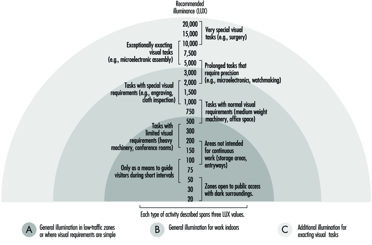
The level of illumination is measured with a luxometer that converts luminous energy into an electrical signal, which is then amplified and offers an easy reading on a calibrated scale of lux. When selecting a certain level of illumination for a particular work station the following points should be studied:
- the nature of the work
- reflectance of the object and of the immediate surroundings
- differences with natural light and the need for daytime illumination
- the worker’s age.
Units and magnitudes of illumination
Several magnitudes are commonly used in the field of illumination. The basic ones are:
Luminous flux: Luminous energy emitted per unit of time by a light source. Unit: lumen (lm).
Luminous intensity: Luminous flux emitted in a given direction by a light that is not equally distributed. Unit: candela (cd).
Level of illumination: Level of illumination of a surface of one square metre when it receives a luminous flux of one lumen. Unit: lux = lm/m2.
Luminance or photometric brilliance: Is defined for a surface in a particular direction, and is the relation between luminous intensity and the surface seen by an observer situated in the same direction (apparent surface). Unit: cd/m2.
Contrast: Difference in luminance between an object and its surroundings or between different parts of an object.
Reflectance: Proportion of light that is reflected by a surface. It is a non-dimensional quantity. Its value ranges between 0 and 1.
Factors that affect the visibility of objects
The degree of safety with which a task is executed depends, in large part, on the quality of illumination and on visual capacities. The visibility of an object can be altered in many ways. One of the most important is the contrast of luminances due to reflection factors, to shadows, or to colours of the object itself, and to the reflection factors of colour. What the eye really perceives are the differences of luminance between an object and its surroundings, or between different parts of the same object. Table 1 lists the contrasts between colours in descending order.
The luminance of an object, of its surroundings, and of the work area influence the ease with which an object is seen. It is therefore of key importance that the area where the visual task is performed, and its surroundings, be carefully analysed.
Table 1. Colour contrasts
|
Colour contrasts in descending order |
|
|
Colour of the object |
Colour of the background |
|
Black |
Yellow |
|
Green |
White |
|
Red |
White |
|
Blue |
White |
|
White |
Blue |
|
Black |
White |
|
Yellow |
Black |
|
White |
Red |
|
White |
Green |
|
White |
Black |
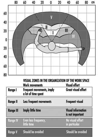
The size of the object that must be observed, which may be adequate or not depending on the distance and the angle of vision of the observer, is another factor. These last two factors determine the arrangement of the work station, classifying different zones according to their ease of vision. We can establish five zones in the work area (see figure 2).
Figure 2. Distribution of visual zones in the work station
Another factor is the time frame during which vision occurs. The time of exposure will be greater or smaller depending on whether the object and the observer are static, or whether one or both of them are moving. The adaptive capacity of the eye to adjust automatically to the different illuminations of objects can also have considerable influence on visibility.
Light distribution; glare
Key factors in the conditions that affect vision are the distribution of light and the contrast of luminances. In so far as the distribution of light is concerned, it is preferable to have good general illumination instead of localized illumination in order to avoid glare. For this reason, electrical accessories should be distributed as uniformly as possible in order to avoid differences in luminous intensity. Constant shuttling through zones that are not uniformly illuminated causes eye fatigue, and with time this can lead to reduced visual output.
Glare is produced when a brilliant source of light is present in the visual field; the result is a diminution in the capacity to distinguish objects. Workers who suffer the effects of glare constantly and successively can suffer from eye strain as well as from functional disorders, even though in many cases they are not aware of it.
Glare can be direct when its origin is bright sources of light directly in the line of vision, or by reflection when light is reflected on surfaces with high reflectance. The factors involved in glare are:
- Luminance of the source of light: The maximum tolerable lumi nance by direct observation is 7,500 cd/m2. Figure 3 shows some of the approximate values of luminance for several sources of light.
- Location of the source of light: This kind of glare occurs when the source of light is within a 45-degree angle of the observer’s line of sight, and will be minimized to the degree that the source of light is placed beyond that angle. Ways and methods of avoiding direct and reflective glare can be seen in the following figures (see figure 4).
Figure 3. Approximate values of luminance
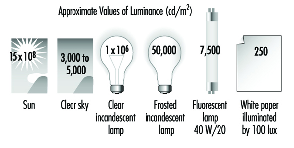
Figure 4. Factors that affect glare

In general, there is more glare when sources of light are mounted at lower elevations or when installed in large rooms, because sources of light in large rooms or sources of light that are too low can easily fall within the angle of vision that produces glare.
3. Distribution of luminance among different objects and surfaces: The greater the differences in luminance are among the objects within the field of vision, the greater will be the glare created and the greater will be the deterioration in the capacity to see due to the effects on the adaptive processes of sight. The maximum recommended luminance disparities are:
- visual task—work surface: 3:1
- visual task—surroundings: 10:1
4. Time frame of the exposure: Even light sources with a low luminance can cause glare if the length of the exposure is prolonged too much.
Avoiding glare is a relatively simple proposition and can be achieved in different ways. One way, for example, is by placing grilles under the sources of illumination, or by using enveloping diffusers or parabolic reflectors that can direct light properly, or by installing the sources of light in such a way that they will not interfere with the angle of vision. When designing the work site, the correct distribution of luminance is as important as the illumination itself, but it is also important to consider that a distribution of luminance that is too uniform makes the three-dimensional and spatial perception of objects more difficult.
Lighting Systems
The interest in natural illumination has increased recently. This is due less to the quality of illumination it affords than to the well-being that it provides. But since the level of illumination from natural sources is not uniform, an artificial lighting system is required.
The most common lighting systems used are the following:
General uniform illumination
In this system light sources are spread out evenly without regard to the location of the work stations. The average level of illumination should be equal to the level of illumination required for the task that will be carried out. These systems are used mainly in workplaces where work stations are not fixed.
It should conform to three fundamental characteristics: The first is to be equipped with anti-glare devices (grilles, diffusers, reflectors and so on). The second is that it should distribute a fraction of the light toward the ceiling and the upper part of the walls. And the third is that the light sources should be installed as high as possible, to minimize glare and achieve illumination that is as homogeneous as possible. (See figure 5)
Figure 5. Lighting systems
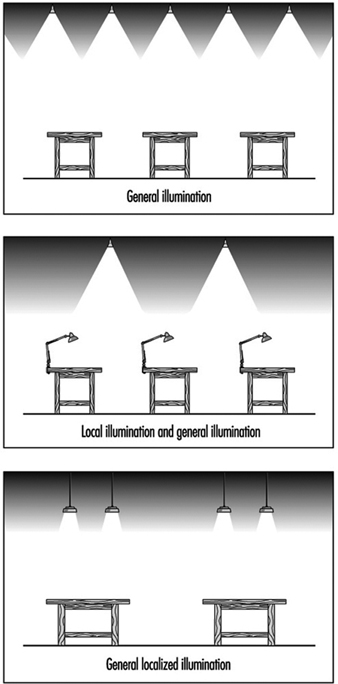
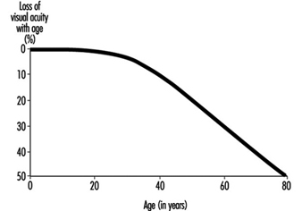
This system tries to reinforce the general illumination scheme by placing lamps close to the work surfaces. These types of lamps often produce glare, and reflectors should be placed in such a way that they block the source of light from the direct sight of the worker. The use of localized illumination is recommended for those applications where visual demands are very critical, such as levels of illumination of 1,000 lux or greater. Generally, visual capacity deteriorates with the age of the worker, which makes it necessary to increase the level of general illumination or to second it with localized illumination. This phenomenon can be clearly appreciated in figure 6.
Figure 6. Loss of visual acuity with age
General localized illumination
This type of illumination consists of ceiling sources distributed with two things in mind—the illumination characteristics of the equipment and the illumination needs of each work station. This type of illumination is indicated for those spaces or work areas that will require a high level of illumination, and it requires knowing the future location of each work station in advance of the design stage.
Colour: Basic Concepts
Selecting an adequate colour for a worksite contributes a great deal to the efficiency, safety and general well-being of the employees. In the same way, the finish of the surfaces and of the equipment found in the work environment contributes to creating pleasant visual conditions and a pleasant work environment.
Ordinary light consists of electromagnetic radiations of different wavelengths that correspond to each of the bands of the visible spectrum. By mixing red, yellow and blue light we can obtain most of the visible colours, including white. Our perception of the colour of an object depends on the colour of the light with which it is illuminated and on the way the object itself reflects light.
Lamps can be classified into three categories depending on the appearance of the light they emit:
- colour with a warm appearance: a white, reddish light recommended for residential use
- colour with intermediate appearance: a white light recommended for worksites
- colour with a cold appearance: a white, bluish light recommended for tasks that require a high level of illumination or for hot climates.
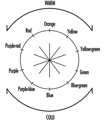
Colours may also be classified as warm or cold according to their tonality (see figure 7).
Figure 7. Tonality of "warm" and "cold" colours
Contrast and temperature of different colours
Colour contrasts are influenced by the colour of the light selected, and for that reason the quality of illumination will depend on the colour of the light chosen for an application. The selection of the colour of light to be used should be made based on the task that will be carried out under it. If the colour is close to white, the rendition of colour and the diffusion of light will be better. The more light approaches the red end of the spectrum the worse the reproduction of colour will be, but the environment will be warmer and more inviting.
The colour appearance of illumination depends not only on the colour of light, but also on the level of luminous intensity. A colour temperature is associated with the different forms of illumination. The sensation of satisfaction with the illumination of a given environment depends on this colour temperature. In this way, for example, a 100 W incandescent filament light bulb has a colour temperature of 2,800 K, a fluorescent tube has a colour temperature of 4,000 K and an overcast sky has a colour temperature of 10,000 K.
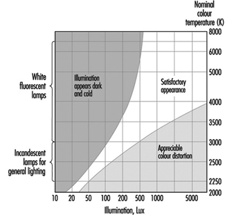
Kruithof defined, through empirical observations, a diagram of well-being for different levels of illumination and colour temperatures in a given environment (see figure 8). In this way, he demonstrated that it is possible to feel comfortable in certain environments with low levels of illumination if the colour temperature is also low—if the level of illumination is one candle, for example, with a colour temperature of 1,750 K.
Figure 8. Comfort diagram as a function of illumination and colour temperatures
The colours of electric lamps can be subdivided into three groups related to their colour temperatures:
- daylight white—around 6,000 K
- neutral white—around 4,000 K
- warm white—around 3,000 K
Combination and selection of colours
The selection of colours is very relevant when we consider it together with those functions where identifying the objects that must be manipulated is important. It is also relevant when delimiting avenues of communication and in those tasks that require sharp contrast.
The selection of tonality is not as important a question as the selection of the proper reflective qualities of a surface. There are several recommendations that apply to this aspect of work surfaces:
Ceilings: The surface of a ceiling should be as white as possible (with a reflection factor of 75%), because light will then reflect from it in a diffuse way, dissipating darkness and reducing the glare from other surfaces. This will also mean a savings in artificial lighting.
Walls and floors: The surfaces of walls at eye level can produce glare. Pale colours with reflective factors of 50 to 75% tend to be adequate for walls. While glossy paints tend to last longer than matte colours, they are more reflective. Walls should therefore have a matte or semi-gloss finish.
Floors should be finished in slightly darker colours than walls and ceilings to avoid glare. The reflective factor of floors should be between 20 and 25%.
Equipment: Work surfaces, machinery and tables should have reflective factors of between 20 and 40%. Equipment should have a lasting finish of pure colour—light browns or greys—and the material should not be shiny.
The proper use of colours in the work environment facilitates well-being, increases productivity and can have a positive impact on quality. It can also contribute to better organization and the prevention of accidents.
There is a generalized belief that whitening the walls and ceilings and supplying adequate levels of illumination is all that can possibly be done as far as the visual comfort of employees is concerned. But these comfort factors can be improved by combining white with other colours, thus avoiding the fatigue and the boredom that characterize monochromatic environments. Colours also have an effect on a person’s level of stimulation; warm colours tend to activate and relax, while cold colours are used to induce the individual to release or liberate his or her energy.
The colour of light, its distribution, and the colours used in a given space are, among others, key factors that influence the sensations a person feels. Given the many colours and comfort factors that exist, it is impossible to set precise guidelines, especially considering that all these factors must be combined according to the characteristics and the requirements of a particular work station. A number of basic and general practical rules can be listed, however, that can help create a liveable environment:
- Bright colours produce comfortable, stimulating and serene feelings, while dark colours tend to have a depressing effect.
- Sources of warm-coloured light help reproduce warm colours well. Warm-coloured objects are more pleasing to the eye in warm light than in cold light.
- Clear and dull colours (like pastels) are very appropriate as background colours, while objects should have rich and saturated colours.
- Warm colours excite the nervous system and give the sensation that temperature is rising.
- Cold colours are preferable for objects. They have a calming effect and can be used to produce the effect of curvature. Cold colours help create the sensation that temperature is dropping.
- The sensation of colour of an object depends on the background colour and on the effect of the light source on its surface.
- Environments that are physically cold or hot can be tempered by using warm or cold lighting, respectively.
- The intensity of a colour will be inversely proportional to the part of the normal visual field that it occupies.
- The spatial appearance of a room can be influenced by colour. A room will seem to have a lower ceiling if its walls are painted a bright colour and the floor and ceiling are darker, and it will seem to have a higher ceiling if the walls are darker and the ceiling is bright.
Identifying objects through colour
The selection of colours can influence the effectiveness of lighting systems by influencing the fraction of light that is reflected. But colour also plays a key role when it comes to identifying objects. We can use brilliant and eye-catching colours or colour contrasts to highlight situations or objects that require special attention. Table 2 lists some of the factors of reflection for different colours and materials.
Table 2. Reflection factors of different colours and materials illuminated with white light
|
Colour/material |
Reflection factor (%) |
|
White |
100 |
|
White paper |
80–85 |
|
Ivory, lime-yellow |
70–75 |
|
Bright yellow, light ochre, light green, pastel blue, light pink, cream |
60–65 |
|
Lime-green, pale gray, pink, orange, blue-gray |
50–55 |
|
Blond wood, blue sky |
40–45 |
|
Oak, dry concrete |
30–35 |
|
Deep red, leaf-green, olive-green, meadow-green |
20–25 |
|
Dark blue, purple |
10–15 |
|
Black |
0 |
In any case, identification by colour should be employed only when it is truly necessary, since identification by colour will work properly only if there are not too many objects that are highlighted by colour. The following are some recommendations for identifying different elements by colour:
- Fire and safety equipment: It is advisable to identify this equipment by placing a recognizable graphic on the nearest wall so that it can be found quickly.
- Machinery: The colouring of stop or emergency devices with bright colours on all machinery is critical. It is also advisable to mark with colour the areas that need lubrication or periodic maintenance, which can add ease and functionality to these procedures.
- Tubing and pipes: If they are important or carry dangerous substances the best advice is to colour them completely. In some cases it may be enough to colour only a line along their length.
- Stairways: In order to make descent easier, one band for every step is preferable to several.
- Risks: Colour should be used to identify a risk only when the risk cannot be eliminated. Identification will be much more effective if it is carried out according to a predetermined colour code.
General Lighting Conditions
Lighting is provided within interiors in order to satisfy the following requirements:
- to assist in providing a safe working environment
- to assist in the performance of visual tasks
- to develop an appropriate visual environment.
The provision of a safe working environment has to be at the top of the list of priorities, and, in general, safety is increased by making hazards clearly visible. The order of priority of the other two requirements will depend to a large extent upon the use to which the interior is put. Task performance can be improved by ensuring that task detail is easier to see, while appropriate visual environments are developed by varying the lighting emphasis given to objects and surfaces within an interior.
Our general feeling of well-being, including morale and fatigue, is influenced by light and colour. Under low lighting levels, objects would have little or no colour or shape and there would be a loss in perspective. Conversely an excess of light may be just as unwanted as too little light.
In general, people prefer a room with daylight to a room which is windowless. Furthermore, contact with the outside world is considered to aid the feeling of well-being. The introduction of automatic lighting controls, together with high-frequency dimming of fluorescent lamps, has made it possible to provide interiors with a controlled combination of daylight and artificial light. This has the added benefit of saving on energy costs.
Perception of the character of an interior is influenced by both the brightness and colour of visible surfaces, both interior and exterior. The general lighting conditions within an interior can be achieved by using daylight or artificial lighting, or more likely by a combination of both.
Evaluation of Lighting
General requirements
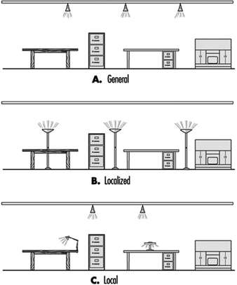
Lighting systems used in commercial interiors can be sub-divided into three major categories—general lighting, localized lighting and local lighting.
General lighting installations typically provide an approximately uniform illuminance over the whole of the working plane. Such systems are often based upon the lumen method of design, where an average illuminance is:
Average illuminance (lux) =![]()
Localized lighting systems provide illuminance on general work areas with a simultaneous reduced level of illuminance in adjacent areas.
Local lighting systems provide illuminance for relatively small areas incorporating visual tasks. Such systems are normally complemented by a specified level of general lighting. Figure 1 illustrates the typical differences between the systems described.
Figure 1. Lighting systems
Where visual tasks are to be performed it is essential to achieve a demanded level of illuminance and to consider the circumstances that influence its quality.
The use of daylight to illuminate tasks has both merits and limitations. Windows admitting daylight into an interior provide good three-dimensional modelling, and though the spectral distribution of daylight varies throughout the day, its colour rendering is generally considered to be excellent.
However, a constant illuminance on a task cannot be provided by natural daylight only, due to its wide variability, and if the task is within the same field of view as a bright sky, then disabling glare is likely to occur, thereby impairing task performance. The use of daylight for task illuminance has only partial success, and artificial lighting, over which greater control can be exercised, has a major role to play.
Since the human eye will perceive surfaces and objects only through light which is reflected from them, it follows that surface characteristics and reflectance values together with the quantity and quality of light will influence the appearance of the environment.
When considering the lighting of an interior it is essential to determine the illuminance level and to compare it with recommended levels for different tasks (see table 1).
Table 1. Typical recommended levels of maintained illuminance for different locations or visual tasks
|
|
Typical recommended level of maintained illuminance (lux) |
|
General offices |
500 |
|
Computer workstations |
500 |
|
Factory assembly areas |
|
|
Rough work |
300 |
|
Medium work |
500 |
|
Fine work |
750 |
|
Very fine work |
|
|
Instrument assembly |
1,000 |
|
Jewellery assembly/repairs |
1,500 |
|
Hospital operating theatres |
50,000 |
Lighting for visual tasks
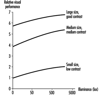
The ability of the eye to discern detail—visual acuity—is significantly influenced by task size, contrast and the viewer’s visual performance. Increase in the quantity and quality of lighting will also significantly improve visual performance. The effect of lighting on task performance is influenced by the size of the critical details of the task and upon the contrast between task and surrounding background. Figure 2 shows the effects of illuminance upon visual acuity. When considering visual task lighting it is important to consider the ability of the eye to carry out the visual task with both speed and accuracy. This combination is known as visual performance. Figure 3 gives typical effects of illuminance on the visual performance of a given task.
Figure 2. Typical relationship between visual acuity and illuminance
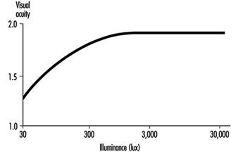
Figure 3. Typical relationship between visual performance and illuminance
The prediction of illuminance reaching a working surface is of prime importance in lighting design. However, the human visual system responds to the distribution of luminance within the field of view. The scene within a visual field is interpreted by differentiating between surface colour, reflectance and illumination. Luminance depends upon both the illuminance on, and reflectance of, a surface. Both illuminance and luminance are objective quantities. The response to brightness, however, is subjective.
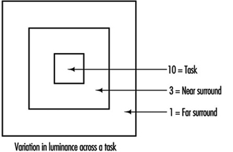
In order to produce an environment which provides visual satisfaction, comfort and performance, luminances within the field of view need to be balanced. Ideally the luminances surrounding a task should decrease gradually, thereby avoiding harsh contrasts. Suggested variation in luminance across a task is shown in figure 4.
Figure 4. Variation in luminance across a task
The lumen method of lighting design leads to an average horizontal plane illuminance on the working plane, and it is possible to use the method to establish average illuminance values on the walls and ceilings within an interior. It is possible to convert average illuminance values into average luminance values from details of the mean reflectance value of the room surfaces.
The equation relating luminance and illuminance is: ![]()
Figure 5. Typical relative illuminance values together with suggested reflectance values
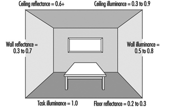
Figure 5 shows a typical office with relative illuminance values (from an overhead general lighting system) on the main room surfaces together with suggested reflectances. The human eye tends to be drawn to that part of the visual scene which is brightest. It follows that higher luminance values usually occur at a visual task area. The eye acknowledges detail within a visual task by discriminating between lighter and darker parts of the task. The variation in brightness of a visual task is determined from calculation of the luminance contrast:
![]()
where
Lt = Luminance of the task
Lb = Luminance of the background
and both luminances are measured in cd·m–2
The vertical lines in this equation signify that all values of luminance contrast are to be considered positive.
The contrast of a visual task will be influenced by the reflectance properties of the task itself. See figure 5.
Optical Control of Lighting
If a bare lamp is used in a luminaire, the distribution of light is unlikely to be acceptable and the system will almost certainly be uneconomical. In such situations the bare lamp is likely to be a source of glare to the room occupants, and while some light may eventually reach the working plane, the effectiveness of the installation is likely to be seriously reduced because of the glare.
It will be evident that some form of light control is required, and the methods most frequently employed are detailed below.
Obstruction
If a lamp is installed within an opaque enclosure with only a single aperture for the light to escape, then the light distribution will be very limited, as shown in figure 6.
Figure 6. Lighting output control by obstruction

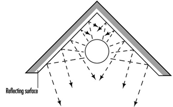
Reflection
This method uses reflective surfaces, which may vary from a highly matt finish to a highly specular or mirror-like finish. This method of control is more efficient than obstruction, since stray light is collected and redirected to where it is required. The principle involved is shown in figure 7.
Figure 7. Light output control by reflection
Diffusion
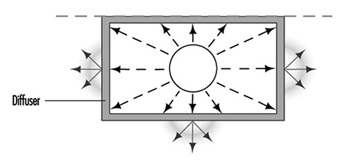
If a lamp is installed within a translucent material, the apparent size of the light source is increased with a simultaneous reduction in its brightness. Practical diffusers unfortunately absorb some of the emitted light, which consequently reduces the overall efficiency of the luminaire. Figure 8 illustrates the principle of diffusion.
Figure 8. Light output control by diffusion
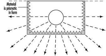
Refraction
This method uses the “prism” effect, where typically a prism material of glass or plastic “bends” the rays of light and in so doing redirects the light to where it is required. This method is extremely suitable for general interior lighting. It has the advantage of combining good glare control with an acceptable efficiency. Figure 9 shows how refraction assists in optical control.
In many cases a luminaire will use a combination of the methods of optical control described.
Figure 9. Light output control by refraction
Luminance distribution
The light output distribution from a luminaire is significant in determining the visual conditions subsequently experienced. Each of the four methods of optical control described will produce differing light output distribution properties from the luminaire.
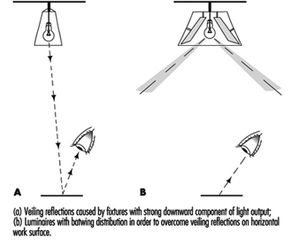
Veiling reflections often occur in areas where VDUs are installed. The usual symptoms experienced in such situations are reduced ability to read correctly from the text on a screen due to the appearance of unwanted high-luminance images on the screen itself, typically from overhead luminaires. A situation can develop where veiling reflections also appear on paper on a desk in an interior.
If the luminaires in an interior have a strong vertically downward component of light output, then any paper on a desk beneath such a luminaire will reflect the light source into the eyes of an observer who is reading from or working on the paper. If the paper has a gloss finish, the situation is aggravated.
The solution to the problem is to arrange for the luminaires used to have a light output distribution which is predominantly at an angle to the downward vertical, so that following the basic laws of physics (angle of incidence = angle of reflection) the reflected glare will be minimized. Figure 10 shows a typical example of both the problem and the cure. The light output distribution from the luminaire used to overcome the problem is referred to as a batwing distribution.
Figure 10. Veiling reflections
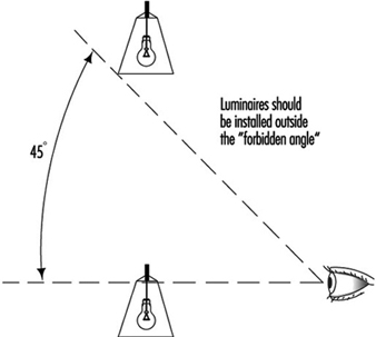
Light distribution from luminaires can also lead to direct glare, and in an attempt to overcome this problem, local lighting units should be installed outside the 45-degree “forbidden angle”, as shown in figure 11.
Figure 11. Diagrammatic representation of the forbidden angle
Optimal Lighting Conditions for Visual Comfortand Performance
It is appropriate when investigating lighting conditions for visual comfort and performance to consider those factors affecting the ability to see detail. These can be sub-divided into two categories—characteristics of the observer and characteristics of the task.
Characteristics of the observer.
These include:
- sensitivity of the individual’s visual system to size, contrast, exposure time
- transient adaptation characteristics
- susceptibility to glare
- age
- motivational and psychological characteristics.
Characteristics of the task.
These include:
- configuration of detail
- contrast of detail/background
- background luminance
- specularity of detail.
With reference to particular tasks, the following questions need to be answered:
- Are the task details easy to see?
- Is the task likely to be undertaken for lengthy periods?
- If errors result from the performance of the task, are the consequences considered to be serious?
In order to produce optimal workplace lighting conditions it is important to consider the requirements placed upon the lighting installation. Ideally task lighting should reveal colour, size, relief and surface qualities of a task while simultaneously avoiding the creation of potentially dangerous shadows, glare and “harsh” surroundings to the task itself.
Glare.
Glare occurs when there is excessive luminance in the field of view. The effects of glare on vision can be divided into two groups, termed disability glare and discomfort glare.
Consider the example of glare from the headlights of an oncoming vehicle during darkness. The eye cannot adapt simultaneously to the headlights of the vehicle and to the much lower brightness of the road. This is an example of disability glare, since the high luminance light sources produce a disabling effect due to the scattering of light in the optic media. Disability glare is proportional to the intensity of the offending source of light.
Discomfort glare, which is more likely to occur in interiors, can be reduced or even totally eliminated by reducing the contrast between the task and its surroundings. Matt, diffusely reflecting finishes on work surfaces are to be preferred to gloss or specularly reflecting finishes, and the position of any offending light source should be outside the normal field of vision. In general, successful visual performance occurs when the task itself is brighter than its immediate surrounds, but not excessively.
The magnitude of discomfort glare is given a numerical value and compared with reference values in order to predict whether the level of discomfort glare will be acceptable. The method of calculation of glare index values used in the UK and elsewhere is considered under “Measurement”.
Measurement
Lighting surveys
One survey technique often used relies upon a grid of measuring points over the whole area under consideration. The basis of this technique is to divide the whole of the interior into a number of equal areas, each ideally square. The illuminance at the centre of each of the areas is measured at desk-top height (typically 0.85 metres above floor level), and an average value of illuminance is calculated. The accuracy of the value of average illuminance is influenced by the number of measuring points used.
A relationship exists which enables the minimum number of measuring points to be calculated from the value of room index applicable to the interior under consideration.
![]()
Here, length and width refer to the room dimensions, and mounting height is the vertical distance between the centre of the light source and the working plane.
The relationship referred to is given as:
Minimum number of measuring points = (x + 2)2
where “x” is the value of the room index taken to the next highest whole number, except that for all values of RI equal to or greater than 3, x is taken as 4. This equation gives the minimum number of measuring points, but conditions often require more than this minimum number of points to be used.
When considering the lighting of a task area and its immediate surround, variance in illuminance or uniformity of illuminance must be considered.
![]()
Over any task area and its immediate surround, uniformity should be not less than 0.8.
In many workplaces it is unnecessary to illuminate all areas to the same level. Localized or local lighting may provide some degree of energy saving, but whichever system is used the variance in illuminance across an interior must not be excessive.
The diversity of illuminance is expressed as:
![]()
At any point in the major area of the interior, the diversity of illuminance should not exceed 5:1.
Instruments used for measuring illuminance and luminance typically have spectral responses which vary from the response of the human visual system. The responses are corrected, often by the use of filters. When filters are incorporated, the instruments are referred to as colour corrected.
Illuminance meters have a further correction applied which compensates for the direction of incident light falling upon the detector cell. Instruments which are capable of accurately measuring illuminance from varying directions of incident light are said to be cosine corrected.
Measurement of glare index
The system used frequently in the UK, with variations elsewhere, is essentially a two-stage process. The first stage establishes an uncorrected glare index value (UGI). Figure 12 provides an example.
Figure 12. Elevation and plan views of typical interior used in example
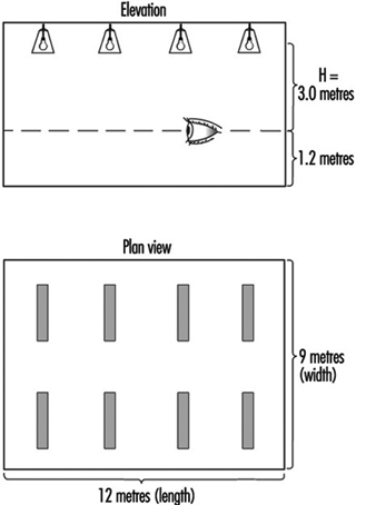
The height H is the vertical distance between the centre of the light source and the eye level of a seated observer, which is normally taken as 1.2 metres above floor level. The major dimensions of the room are then converted into multiples of H. Thus, since H = 3.0 metres, then length = 4H and width = 3H. Four separate calculations of UGI have to be made in order to determine the worst case scenario in accordance with the layouts shown in figure 13.
Figure 13. Possible combinations of luminaire orientation and viewing direction within the interior considered in the example

Tables are produced by lighting equipment manufacturers which specify, for given values of fabric reflectance within a room, values of uncorrected glare index for each combination of values of X and Y.
The second stage of the process is to apply correction factors to the UGI values depending upon values of lamp output flux and deviation in value of height (H).
The final glare index value is then compared with the Limiting Glare Index value for specific interiors, given in references such as the CIBSE Code for Interior Lighting (1994).
" DISCLAIMER: The ILO does not take responsibility for content presented on this web portal that is presented in any language other than English, which is the language used for the initial production and peer-review of original content. Certain statistics have not been updated since the production of the 4th edition of the Encyclopaedia (1998)."