- You are here:
-
Home

-
Part VI. General Hazards
- Electricity

40. Electricity
Chapter Editor: Dominique Folliot
Table of Contents
Figures and Tables
Electricity—Physiological Effects
Dominique Folliot
Static Electricity
Claude Menguy
Prevention And Standards
Renzo Comini
Tables
Click a link below to view table in article context.
1. Estimates of the rate of electrocution-1988
2. Basic relationships in electrostatics-Collection of equations
3. Electron affinities of selected polymers
4. Typical lower flammability limits
5. Specific charge associated with selected industrial operations
6. Examples of equipment sensitive to electrostatic discharges
Figures
Point to a thumbnail to see figure caption, click to see figure in article context.


Electricity-Physiological Effects
The study of the hazards, electrophysiology and prevention of electrical accidents requires an understanding of several technical and medical concepts.
The following definitions of electrobiological terms are taken from chapter 891 of the International Electrotechnical Vocabulary (Electrobiology) (International Electrotechnical Commission) (IEC) (1979).
An electrical shock is the physiopathological effect resulting from the direct or indirect passage of an external electrical current through the body. It includes direct and indirect contacts and both unipolar and bipolar currents.
Individuals—living or deceased—having suffered electrical shocks are said to have suffered electrification; the term electrocution should be reserved for cases in which death ensues. Lightning strikes are fatal electrical shocks resulting from lightning (Gourbiere et al. 1994).
International statistics on electrical accidents have been compiled by the International Labour Office (ILO), the European Union (EU), the Union internationale des producteurs et distributeurs d’énergie électrique (UNIPEDE), the International Social Security Association (ISSA) and the TC64 Committee of the International Electrotechnical Commission. Interpretation of these statistics is hampered by variations in data collection techniques, insurance policies and definitions of fatal accidents from country to country. Nevertheless, the following estimates of the rate of electrocution are possible (table 1).
Table 1. Estimates of the rate of electrocution - 1988
|
Electrocutions |
Total |
|
|
United States* |
2.9 |
714 |
|
France |
2.0 |
115 |
|
Germany |
1.6 |
99 |
|
Austria |
0.9 |
11 |
|
Japan |
0.9 |
112 |
|
Sweden |
0.6 |
13 |
* According to the National Fire Protection Association (Massachusetts, US) these US statistics are more reflective of extensive data collection and legal reporting requirements than of a more dangerous environment. US statistics include deaths from exposure to public utility transmission systems and electrocutions caused by consumer products. In 1988, 290 deaths were caused by consumer products (1.2 deaths per million inhabitants). In 1993, the rate of death by electrocution from all causes dropped to 550 (2.1 deaths per million inhabitants); 38% were consumer product-related (0.8 deaths per million inhabitants).
The number of electrocutions is slowly decreasing, both in absolute terms and, even more strikingly, as a function of the total consumption of electricity. Approximately half of electrical accidents are occupational in origin, with the other half occurring at home and during leisure activities. In France, the average number of fatalities between 1968 and 1991 was 151 deaths per year, according to the Institut national de la santé et de la recherche médicale (INSERM).
Physical and Physiopathological Basis of Electrification
Electrical specialists divide electrical contacts into two groups: direct contacts, involving contact with live components, and indirect contacts, involving grounded contacts. Each of these requires fundamentally different preventive measures.
From a medical point of view, the current’s path through the body is the key prognostic and therapeutic determinant. For example, bipolar contact of a child’s mouth with an extension cord plug causes extremely serious burns to the mouth—but not death if the child is well insulated from the ground.
In occupational settings, where high voltages are common, arcing between an active component carrying a high voltage and workers who approach too closely is also possible. Specific work situations can also affect the consequences of electrical accidents: for example, workers may fall or act inappropriately when surprised by an otherwise relatively harmless electrical shock.
Electrical accidents may be caused by the entire range of voltages present in workplaces. Every industrial sector has its own set of conditions capable of causing direct, indirect, unipolar, bipolar, arcing, or induced contact, and, ultimately, accidents. While it is of course beyond the scope of this article to describe all human activities which involve electricity, it is useful to remind the reader of the following major types of electrical work, which have been the object of international preventive guidelines described in the chapter on prevention:
- activities involving work on live wires (the application of extremely rigorous protocols has succeeded in reducing the number of electrifications during this type of work)
- activities involving work on unpowered wires, and
- activities performed in the vicinity of live wires (these activities require the most attention, as they are often performed by personnel who are not electricians).
Physiopathology
All the variables of Joule’s law of direct current—
W=V x I x t = RI2t
(the heat produced by an electric current is proportional to the resistance and the square of the current)—are closely interrelated. In the case of alternating current, the effect of frequency must also be taken into account (Folliot 1982).
Living organisms are electrical conductors. Electrification occurs when there is a potential difference between two points in the organism. It is important to emphasize that the danger of electrical accidents arises not from mere contact with a live conductor, but rather from simultaneous contact with a live conductor and another body at a different potential.
The tissues and organs along the current path may undergo functional motor excitation, in some cases irreversible, or may suffer temporary or permanent injury, generally as a result of burns. The extent of these injuries is a function of the energy released or the quantity of electricity passing through them. The transit time of the electric current is therefore critical in determining the degree of injury. (For example, electric eels and rays produce extremely unpleasant discharges, capable of inducing a loss of consciousness. However, despite a voltage of 600V, a current of approximately 1A and a subject resistance of approximately 600 ohms, these fish are incapable of inducing a lethal shock, since the discharge duration is too brief, of the order of tens of microseconds.) Thus, at high voltages (>1,000V), death is often due to the extent of the burns. At lower voltages, death is a function of the amount of electricity (Q=I x t), reaching the heart, determined by the type, location and area of the contact points.
The following sections discuss the mechanism of death due to electrical accidents, the most effective immediate therapies and the factors determining the severity of injury—namely, resistance, intensity, voltage, frequency and wave-form.
Causes of Death in Electrical Accidents in Industry
In rare cases, asphyxia may be the cause of death. This may result from prolonged tetanus of the diaphragm, inhibition of the respiratory centres in cases of contact with the head, or very high current densities, for example as a result of lightning strikes (Gourbiere et al. 1994). If care can be provided within three minutes, the victim may be revived with a few puffs of mouth-to-mouth resuscitation.
On the other hand, peripheral circulatory collapse secondary to ventricular fibrillation remains the main cause of death. This invariably develops in the absence of cardiac massage applied simultaneously with mouth-to-mouth resuscitation. These interventions, which should be taught to all electricians, should be maintained until the arrival of emergency medical aid, which almost always takes more than three minutes. A great many electropathologists and engineers around the world have studied the causes of ventricular fibrillation, in order to design better passive or active protective measures (International Electrotechnical Commission 1987; 1994). Random desynchronization of the myocardium requires a sustained electric current of a specific frequency, intensity and transit time. Most importantly, the electrical signal must arrive at the myocardium during the so-called vulnerable phase of the cardiac cycle, corresponding to the start of the T-wave of the electrocardiogram.
The International Electrotechnical Commission (1987; 1994) has produced curves describing the effect of current intensity and transit time on the probability (expressed as percentages) of fibrillation and the hand-foot current path in a 70-kg male in good health. These tools are appropriate for industrial currents in the frequency range of 15 to 100 Hz, with higher frequencies currently under study. For transit times of less than 10 ms, the area under the electrical signal curve is a reasonable approximation of the electrical energy.
Role of Various Electrical Parameters
Each of the electrical parameters (current, voltage, resistance, time, frequency) and wave-form are important determinants of injury, both in their own right and by virtue of their interaction.
Current thresholds have been established for alternating current, as well as for other conditions defined above. The current intensity during electrification is unknown, since it is a function of tissue resistance at the moment of contact (I = V/R), but is generally perceptible at levels of approximately 1 mA. Relatively low currents can cause muscular contractions that may prevent a victim from letting go of an energized object. The threshold of this current is a function of condensity, contact area, contact pressure and individual variations. Virtually all men and almost all women and children can let go at currents up to 6 mA. At 10 mA it has been observed that 98.5% of men and 60% of women and 7.5% of children can let go. Only 7.5% of men and no women or children can let go at 20mA. No one can let go at 30mA and greater.
Currents of approximately 25 mA may cause tetanus of the diaphragm, the most powerful respiratory muscle. If contact is maintained for three minutes, cardiac arrest may also ensue.
Ventricular fibrillation becomes a danger at levels of approximately 45 mA, with a probability in adults of 5% after a 5-second contact. During heart surgery, admittedly a special condition, a current of 20 to 100 × 10–6A applied directly to the myocardium is sufficient to induce fibrillation. This myocardial sensitivity is the reason for strict standards applied to electromedical devices.
All other things (V, R, frequency) being equal, current thresholds also depend on the wave-form, animal species, weight, current direction in the heart, ratio of the current transit time to the cardiac cycle, point in the cardiac cycle at which the current arrives, and individual factors.
The voltage involved in accidents is generally known. In cases of direct contact, ventricular fibrillation and the severity of burns are directly proportional to voltage, since
V = RI and W = V x I x t
Burns arising from high-voltage electric shock are associated with many complications, only some of which are predictable. Accordingly accident victims must be cared for by knowledgeable specialists. Heat release occurs primarily in the muscles and neurovascular bundles. Plasma leakage following tissue damage causes shock, in some cases rapid and intense. For a given surface area, electrothermic burns—burns caused by an electrical current—are always more severe than other types of burn. Electrothermic burns are both external and internal and, although this may not be initially apparent, can induce vascular damage with serious secondary effects. These include internal stenoses and thrombi which, by virtue of the necrosis they induce, often necessitate amputation.
Tissue destruction is also responsible for the release of chromoproteins such as myoglobin. Such release is also observed in victims of crush injuries, although the extent of release is remarkable in victims of high-voltage burns. Myoglobin precipitation in renal tubules, secondary to acidosis brought on by anoxia and hyperkalaemia, is thought to be the cause of anuria. This theory, experimentally confirmed but not universally accepted, is the basis for recommendations for immediate alkalization therapy. Intravenous alkalization, which also corrects hypovolaemia and acidosis secondary to cell death, is the recommended practice.
In the case of indirect contacts, the contact voltage (V) and conventional voltage limit must also be taken into account.
The contact voltage is the voltage to which a person is subjected on simultaneously touching two conductors between which a voltage differential exists due to defective insulation. The intensity of the resultant current flow depends on the resistances of the human body and the external circuit. This current should not be allowed to rise above safe levels, which is to say that it must conform to safe time-current curves. The highest contact voltage that can be tolerated indefinitely without inducing electropathological effects is termed the conventional voltage limit or, more intuitively, the safety voltage.
The actual value of the resistance during electrical accidents is unknown. Variations in in-series resistances—for example, clothes and shoes—explain much of the variation observed in the effects of ostensibly similar electrical accidents, but exert little influence on the outcome of accidents involving bipolar contacts and high-voltage electrifications. In cases involving alternating current, the effect of capacitive and inductive phenomena must be added to the standard calculation based on voltage and current (R=V/I).
The resistance of the human body is the sum of the skin resistance (R) at the two points of contact and the body’s internal resistance (R). Skin resistance varies with environmental factors and, as noted by Biegelmeir (International Electrotechnical Commission 1987; 1994), is partially a function of the contact voltage. Other factors such as pressure, contact area, the state of the skin at the point of contact, and individual factors also influence resistance. It is thus unrealistic to attempt to base preventive measures on estimates of skin resistance. Prevention should instead be based on the adaptation of equipment and procedures to humans, rather than the reverse. In order to simplify matters, the IEC has defined four types of environment—dry, humid, wet and immersion—and has defined parameters useful for the planning of prevention activities in each case.
The frequency of the electrical signal responsible for electrical accidents is generally known. In Europe, it is almost always 50 Hz and in the Americas, it is generally 60 Hz. In rare cases involving railways in countries such as Germany, Austria and Switzerland, it may be 16 2/3 Hz, a frequency which theoretically represents a greater risk of tetanization and of ventricular fibrillation. It should be recalled that fibrillation is not a muscle reaction but is caused by repetitive stimulation, with a maximum sensitivity at approximately 10 Hz. This explains why, for a given voltage, extremely low-frequency alternating current is considered to be three to five times more dangerous than direct current with regard to effects other than burns.
The thresholds described previously are directly proportional to the frequency of the current. Thus, at 10 kHz, the detection threshold is ten times higher. The IEC is studying revised fibrillation hazard curves for frequencies above 1,000 Hz (International Electrotechnical Commission 1994).
Above a certain frequency, the physical laws governing penetration of current into the body change completely. Thermal effects related to the amount of energy released become the main effect, as capacitive and inductive phenomena start to predominate.
The wave-form of the electrical signal responsible for an electrical accident is usually known. It may be an important determinant of injury in accidents involving contact with capacitors or semiconductors.
Clinical Study of Electric Shock
Classically, electrifications have been divided into low- (50 to 1,000 V) and high- (>1,000 V) voltage incidents.
Low voltage is a familiar, indeed omnipresent, hazard, and shocks due to it are encountered in domestic, leisure, agricultural and hospital settings as well as in industry.
In reviewing the range of low-voltage electric shocks, from the most trivial to the most serious, we must start with uncomplicated electrical shock. In these cases, victims are able to remove themselves from harm on their own, retain consciousness and maintain normal ventilation. Cardiac effects are limited to simple sinus tachycardia with or without minor electrocardiographic abnormalities. Despite the relatively minor consequences of such accidents, electrocardiography remains an appropriate medical and medico-legal precaution. Technical investigation of these potentially serious incidents is indicated as a complement to clinical examination (Gilet and Choquet 1990).
Victims of shock involving somewhat stronger and longer-lasting electrical contact shocks may suffer from perturbations or loss of consciousness, but completely recover more or less rapidly; treatment accelerates recovery. Examination generally reveals neuromuscular hypertonias, hyper-reflective ventilation problems and congestion, the last of which is often secondary to oropharyngeal obstruction. Cardiovascular disorders are secondary to hypoxia or anoxia, or may take the form of tachycardia, hypertension and, in some cases, even infarction. Patients with these conditions require hospital care.
The occasional victims who lose consciousness within a few seconds of contact appear pale or cyanotic, stop breathing, have barely perceptible pulses and exhibit mydriasis indicative of acute cerebral injury. Although usually due to ventricular fibrillation, the precise pathogenesis of this apparent death is, however, irrelevant. The important point is the rapid commencement of well-defined therapy, since it has been known for some time that this clinical state never leads to actual death. The prognosis in these cases of electric shock—from which total recovery is possible— depends on the rapidity and quality of first aid. Statistically, this is most likely to be administered by non-medical personnel, and the training of all electricians in the basic interventions likely to ensure survival is therefore indicated.
In cases of apparent death, emergency treatment must take priority. In other cases, however, attention must be paid to multiple traumas resulting from violent tetanus, falls or the projection of the victim through the air. Once the immediate life-threatening danger has been resolved, trauma and burns, including those caused by low-voltage contacts, should be attended to.
Accidents involving high voltages result in significant burns as well as the effects described for low-voltage accidents. The conversion of electrical energy to heat occurs both internally and externally. In a study of electrical accidents in France made by the medical department of the power utility, EDF-GDF, almost 80% of the victims suffered burns. These can be classified into four groups:
- arc burns, usually involving exposed skin and complicated in some cases by burns from burning clothing
- multiple, extensive and deep electrothermic burns, caused by high-voltage contacts
- classical burns, caused by burning clothing and the projection of burning matter, and
- mixed burns, caused by arcing, burning and current flow.
Follow-up and complementary examinations are performed as required, depending on the particulars of the accident. The strategy used to establish a prognosis or for medico-legal purposes is of course determined by the nature of observed or expected complications. In high-voltage electrifications (Folliot 1982) and lightning strikes (Gourbiere et al. 1994), enzymology and the analysis of chromoproteins and blood clotting parameters are obligatory.
The course of recovery from electrical trauma may well be compromised by early or late complications, especially those involving the cardiovascular, nervous and renal systems. These complications in their own right are sufficient reason to hospitalize victims of high-voltage electrifications. Some complications may leave functional or cosmetic sequelae.
If the current path is such that significant current reaches the heart, cardiovascular complications will be present. The most frequently observed and most benign of these are functional disorders, in the presence or absence of clinical correlates. Arrhythmias—sinus tachycardia, extrasystole, flutter and atrial fibrillation (in that order)—are the most common electrocardiographic abnormalities, and may leave permanent sequelae. Conduction disorders are rarer, and are difficult to relate to electrical accidents in the absence of a previous electrocardiogram.
More serious disorders such as cardiac failure, valve injury and myocardial burns have also been reported, but are rare, even in victims of high-voltage accidents. Clear-cut cases of angina and even infarction have also been reported.
Peripheral vascular injury may be observed in the week following high-voltage electrification. Several pathogenic mechanisms have been proposed: arterial spasm, the action of electrical current on the media and muscular layers of the vessels and modification of the blood clotting parameters.
A wide variety of neurological complications is possible. The earliest to appear is stroke, regardless of whether the victim initially experienced loss of consciousness. The physiopathology of these complications involves cranial trauma (whose presence should be ascertained), the direct effect of current on the head, or the modification of cerebral blood flow and the induction of a delayed cerebral oedema. In addition, medullary and secondary peripheral complications may be caused by trauma or the direct action of electric current.
Sensory disorders involve the eye and the audiovestibular or cochlear systems. It is important to examine the cornea, crystalline lens and fundus of the eye as soon as possible, and to follow up victims of arcing and direct head contact for delayed effects. Cataracts may develop after an intervening symptom-free period of several months. Vestibular disorders and hearing loss are primarily due to blast effects and, in victims of lightning strike transmitted over telephone lines, to electrical trauma (Gourbiere et al. 1994).
Improvements in mobile emergency practices have greatly reduced the frequency of renal complications, especially oligo-anuria, in victims of high-voltage electrifications. Early and careful rehydration and intravenous alkalinization is the treatment of choice in victims of serious burns. A few cases of albuminuria and persistent microscopic haematuria have been reported.
Clinical Portraits and Diagnostic Problems
The clinical portrait of electric shock is complicated by the variety of industrial applications of electricity and the increasing frequency and variety of medical applications of electricity. For a long time, however, electrical accidents were caused solely by lightning strikes (Gourbiere et al. 1994). Lightning strikes may involve quite remarkable quantities of electricity: one out of every three victims of lightning strikes dies. The effects of a lightning strike—burns and apparent death—are comparable to those resulting from industrial electricity and are attributable to electrical shock, the transformation of electrical energy into heat, blast effects and the electrical properties of lightning.
Lightning strikes are three times as prevalent in men as in women. This reflects patterns of work with differing risks for exposure to lightning.
Burns resulting from contact with grounded metallic surfaces of electric scalpels are the most common effects observed in victims of iatrogenic electrification. The magnitude of acceptable leakage currents in electromedical devices varies from one device to another. At the very least, manufacturers’ specifications and usage recommendations should be followed.
To conclude this section, we would like to discuss the special case of electric shock involving pregnant women. This may cause the death of the woman, the foetus or both. In one remarkable case, a live foetus was successfully delivered by Caesarian section 15 minutes after its mother had died as a result of electrocution by a 220 V shock (Folliot 1982).
The pathophysiological mechanisms of abortion caused by electric shock requires further study. Is it caused by conduction disorders in the embryonic cardiac tube subjected to a voltage gradient, or by a tearing of the placenta secondary to vasoconstriction?
The occurrence of electrical accidents such as this happily rare one is yet another reason to require notification of all cases of injuries arising from electricity.
Positive and Medico-Legal Diagnosis
The circumstances under which electric shock occurs are generally sufficiently clear to allow unequivocal aetiological diagnosis. However, this is not invariably the case, even in industrial settings.
The diagnosis of circulatory failure following electric shock is extremely important, since it requires bystanders to commence immediate and basic first aid once the current has been shut off. Respiratory arrest in the absence of a pulse is an absolute indication for the commencement of cardiac massage and mouth-to-mouth resuscitation. Previously, these were only performed when mydriasis (dilation of the pupils), a diagnostic sign of acute cerebral injury, was present. Current practice is, however, to begin these interventions as soon as the pulse is no longer detectable.
Since loss of consciousness due to ventricular fibrillation may take a few seconds to develop, victims may be able to distance themselves from the equipment responsible for the accident. This may be of some medico-legal importance—for example, when an accident victim is found several metres from an electrical cabinet or other source of voltage with no traces of electrical injury.
It cannot be overemphasized that the absence of electrical burns does not exclude the possibility of electrocution. If autopsy of subjects found in electrical environments or near equipment capable of developing dangerous voltages reveals no visible Jelinek lesions and no apparent sign of death, electrocution should be considered.
If the body is found outdoors, a diagnosis of lightning strike is arrived at by the process of elimination. Signs of lightning strike should be searched for within a 50-metre radius of the body. The Museum of Electropathology of Vienna offers an arresting exhibition of such signs, including carbonized vegetation and vitrified sand. Metal objects worn by the victim may be melted.
Although suicide by electrical means remains thankfully rare in industry, death due to contributory negligence remains a sad reality. This is particularly true at non-standard sites, especially those involving the installation and operation of provisional electrical facilities under demanding conditions.
Electrical accidents should by all rights no longer occur, given the availability of effective preventive measures described in the article “Prevention and Standards”.
Static Electricity
All materials differ in the degree to which electric charges can pass through them. Conductors allow charges to flow, while insulators hinder the motion of charges. Electrostatics is the field devoted to studying charges, or charged bodies at rest. Static electricity results when electric charges which do not move are built up on objects. If the charges flow, then a current results and the electricity is no longer static. The current that results from moving charges is commonly referred to by laypeople as electricity, and is discussed in the other articles in this chapter. Static electrification is the term used to designate any process resulting in the separation of positive and negative electrical charges. Conduction is measured with a property called conductance, while an insulator is characterized by its resistivity. Charge separation which leads to electrification can occur as the result of mechanical processes—for example, contact between objects and friction, or the collision of two surfaces. The surfaces can be two solids or a solid and a liquid. The mechanical process can, less commonly, be the rupture or separation of solid or liquid surfaces. This article focuses on contact and friction.
Electrification Processes
The phenomenon of generation of static electricity by friction (triboelectrification) has been known for thousands of years. Contact between two materials is sufficient to induce electrification. Friction is simply a type of interaction which increases the area of contact and generates heat—friction is the general term to describe the movement of two objects in contact; the pressure exerted, its shear velocity and the heat generated are the prime determinants of the charge generated by friction. Sometimes friction will lead to the tearing away of solid particles as well.
When the two solids in contact are metals (metal-metal contact), electrons migrate from one to the other. Every metal is characterized by a different initial potential (Fermi potential), and nature always moves towards equilibrium—that is, natural phenomena work to eliminate the differences in potential. This migration of electrons results in the generation of a contact potential. Because the charges in a metal are very mobile (metals are excellent conductors), the charges will even recombine at the last point of contact before the two metals are separated. It is therefore impossible to induce electrification by bringing together two metals and then separating them; the charges will always flow to eliminate the potential difference.
When a metal and an insulator come into nearly friction-free contact in a vacuum, the energy level of electrons in the metal approaches that of the insulator. Surface or bulk impurities cause this to occur and also prevent arcing (the discharge of electricity between the two charged bodies—the electrodes) upon separation. The charge transferred to the insulator is proportional to the electron affinity of the metal, and every insulator also has an electron affinity, or attraction for electrons, associated with it. Thus, transfer of positive or negative ions from the insulator to the metal is also possible. The charge on the surface following contact and separation is described by equation 1 in table 1.
Table 1. Basic relationships in electrostatics - Collection of equations
Equation 1: Charging by contact of a metal and an insulator
In general, the surface charge density (![]() ) following contact and separation
) following contact and separation
can be expressed by:
![]()
where
e is the charge of an electron
NE is the energy state density at the insulator’s surface
fi is the electron affinity of the insulator, and
fm is the electron affinity of the metal
Equation 2: Charging following contact between two insulators
The following general form of equation 1 applies to the charge transfer
between two insulators with different energy states (perfectly clean surfaces only):
![]()
where NE1 and NE2 are the energy state densities at the surface of the two insulators,
and Ø1 and Ø 2 are the electron affinities of the two insulators.
Equation 3: Maximum surface charge density
The dielectric strength (EG) of the surrounding gas imposes an upper limit on the charge it is
possible to generate on a flat insulating surface. In air, EG is approximately 3 MV/m.
The maximum surface charge density is given by:
![]()
Equation 4: Maximum charge on a spherical particle
When nominally spherical particles are charged by the corona effect, the maximum
charge which each particle can acquire is given by Pauthenier’s limit:
![]()
where
qmax is the maximum charge
a is the particle radius
eI is the relative permittivity and
![]()
Equation 5: Discharges from conductors
The potential of an insulated conductor carrying charge Q is given by V = Q/C and
the stored energy by:
![]()
Equation 6: Time course of potential of charged conductor
In a conductor charged by a constant current (IG), the time course of the
potential is described by:
![]()
where Rf is the conductor’s leak resistance
Equation 7: Final potential of charged conductor
For long time course, t >Rf C, this reduces to:
![]()
and the stored energy is given by:
Equation 8: Stored energy of charged conductor
![]()
When two insulators come into contact, charge transfer occurs because of the different states of their surface energy (equation 2, table 1). Charges transferred to the surface of an insulator can migrate deeper within the material. Humidity and surface contamination can greatly modify the behaviour of charges. Surface humidity in particular increases surface energy state densities by increasing surface conduction, which favours charge recombination, and facilitates ionic mobility. Most people will recognize this from their daily life experiences by the fact that they tend to be subjected to static electricity during dry conditions. The water content of some polymers (plastics) will change as they are being charged. The increase or decrease in water content may even reverse the direction of the charge flow (its polarity).
The polarity (relative positivity and negativity) of two insulators in contact with each other depends on each material’s electron affinity. Insulators can be ranked by their electron affinities, and some illustrative values are listed in table 2. The electron affinity of an insulator is an important consideration for prevention programmes, which are discussed later in this article.
Table 2. Electron affinities of selected polymers*
|
Charge |
Material |
Electron affinity (EV) |
|
– |
PVC (polyvinyl chloride) |
4.85 |
|
Polyamide |
4.36 |
|
|
Polycarbonate |
4.26 |
|
|
PTFE (polytetrafluoroethylene) |
4.26 |
|
|
PETP (polyethylene terephthalate) |
4.25 |
|
|
Polystyrene |
4.22 |
|
|
+ |
Polyamide |
4.08 |
* A material acquires a positive charge when it comes into contact with a material listed above it, and a negative charge when it comes into contact with a material listed below it. The electron affinity of an insulator is multifactorial, however.
Although there have been attempts to establish a triboelectric series which would rank materials so that those which acquire a positive charge upon contact with materials would appear higher in the series than those that acquire a negative charge upon contact, no universally recognized series has been established.
When a solid and a liquid meet (to form a solid-liquid interface), charge transfer occurs due to the migration of ions that are present in the liquid. These ions arise from the dissociation of impurities which may be present or by electrochemical oxidation-reduction reactions. Since, in practice, perfectly pure liquids do not exist, there will always be at least some positive and negative ions in the liquid available to bind to the liquid-solid interface. There are many types of mechanisms by which this binding may occur (e.g., electrostatic adherence to metal surfaces, chemical absorption, electrolytic injection, dissociation of polar groups and, if the vessel wall is insulating, liquid-solid reactions.)
Since substances which dissolve (dissociate) are electrically neutral to begin with, they will generate equal numbers of positive and negative charges. Electrification occurs only if either the positive or the negative charges preferentially adhere to the solid’s surface. If this occurs, a very compact layer, known as the Helmholtz layer is formed. Because the Helmholtz layer is charged, it will attract ions of the opposite polarity to it. These ions will cluster into a more diffuse layer, known as the Gouy layer, which rests on top of the surface of the compact Helmholtz layer. The thickness of the Gouy layer increases with the resistivity of the liquid. Conducting liquids form very thin Gouy layers.
This double layer will separate if the liquid flows, with the Helmholtz layer remaining bound to the interface and the Gouy layer becoming entrained by the flowing liquid. The movement of these charged layers produces a difference in potential (the zeta potential), and the current induced by the moving charges is known as the streaming current. The amount of charge that accumulates in the liquid depends on the rate at which the ions diffuse towards the interface and on the liquid’s resistivity (r). The streaming current is, however, constant over time.
Neither highly insulating nor conducting liquids will become charged—the first because very few ions are present, and the second because in liquids which conduct electricity very well, the ions will recombine very rapidly. In practice, electrification occurs only in liquids with resistivity greater than 107Ωm or less than 1011Ωm, with the highest values observed for r 109 to 1011 Ωm.
Flowing liquids will induce charge accumulation in insulating surfaces over which they flow. The extent to which the surface charge density will build up is limited by (1) how quickly the ions in the liquid recombine at the liquid-solid interface, (2) how quickly the ions in the liquid are conducted through the insulator, or (3) whether surface or bulk arcing through the insulator occurs and the charge is thus discharged. Turbulent flow and flow over rough surfaces favour electrification.
When a high voltage—say several kilovolts—is applied to a charged body (an electrode) which has a small radius (e.g., a wire), the electrical field in the immediate vicinity of the charged body is high, but it decreases rapidly with distance. If there is a discharge of the stored charges, the discharge will be limited to the region in which the electrical field is stronger than the dielectric strength of the surrounding atmosphere, a phenomenon known as the corona effect, because the arcing also emits light. (People may actually have seen small sparks formed when they have personally experienced a shock from static electricity.)
The charge density on an insulating surface can also be changed by the moving electrons that are generated by a high-intensity electrical field. These electrons will generate ions from any gas molecules in the atmosphere with which they come into contact. When the electric charge on the body is positive, the charged body will repel any positive ions which have been created. Electrons created by negatively charged objects will lose energy as they recede from the electrode, and they will attach themselves to gas molecules in the atmosphere, thus forming negative ions which continue to recede away from the charge points. These positive and negative ions can come to rest on any insulating surface and will modify the surface’s charge density. This type of charge is much easier to control and more uniform than the charges created by friction. There are limits to the extent of the charges it is possible to generate in this way. The limit is described mathematically in equation 3 in table 1.
To generate higher charges, the dielectric strength of the environment must be increased, either by creating a vacuum or by metallizing the other surface of the insulating film. The latter stratagem draws the electrical field into the insulator and consequently reduces the field strength in the surrounding gas.
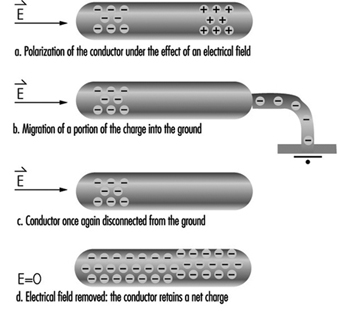
When a conductor in an electrical field (E) is grounded (see figure 1), charges can be produced by induction. Under these conditions, the electrical field induces polarization—the separation of the centres of gravity of the negative and positive ions of the conductor. A conductor temporarily grounded at only one point will carry a net charge when disconnected from the ground, due to the migration of charges in the vicinity of the point. This explains why conducting particles located in a uniform field oscillate between electrodes, charging and discharging at each contact.
Figure 1. Mechanism of charging a conductor by induction
Hazards Associated with Static Electricity
The ill effects caused by the accumulation of static electricity range from the discomfort one experiences when touching a charged object, such as a door handle, to the very serious injuries, even fatalities, which can occur from an explosion induced by static electricity. The physiological effect of electrostatic discharges on humans ranges from uncomfortable prickling to violent reflex actions. These effects are produced by the discharge current and, especially, by the current density on the skin.
In this article we will describe some practical ways in which surfaces and objects can become charged (electrification). When the electrical field induced exceeds the ability of the surrounding environment to withstand the charge (that is, exceeds the dielectric strength of the environment), a discharge occurs. (In air, the dielectric strength is described by Paschen’s curve and is a function of the product of the pressure and the distance between the charged bodies.)
Disruptive discharges can take the following forms:
- sparks or arcs which bridge two charged bodies (two metal electrodes)
- partial, or brush, discharges which bridge a metal electrode and an insulator, or even two insulators; these discharges are termed partial because the conducting path does not totally short-circuit two metal electrodes, but is usually multiple and brushlike
- corona discharges, also known as point effects, which arise in the strong electric field around small-radius charged bodies or electrodes.
Insulated conductors have a net capacitance C relative to ground. This relationship between charge and potential is expressed in equation 5 in table 1.
A person wearing insulating shoes is a common example of an insulated conductor. The human body is an electrostatic conductor, with a typical capacitance relative to ground of approximately 150 pF and a potential of up to 30 kV. Because people can be insulating conductors, they can experience electrostatic discharges, such as the more or less painful sensation sometimes produced when a hand approaches a door handle or other metal object. When the potential reaches approximately 2 kV, the equivalent to an energy of 0.3 mJ will be experienced, although this threshold varies from person to person. Stronger discharges may cause uncontrollable movements resulting in falls. In the case of workers using tools, the involuntary reflex motions may lead to injuries to the victim and others who may be working nearby. Equations 6 to 8 in table 1 describe the time course of the potential.
Actual arcing will occur when the strength of the induced electrical field exceeds the dielectric strength of air. Because of the rapid migration of charges in conductors, essentially all the charges flow to the discharge point, releasing all the stored energy into a spark. This can have serious implications when working with flammable or explosive substances or in flammable conditions.
The approach of a grounded electrode to a charged insulating surface modifies the electric field and induces a charge in the electrode. As the surfaces approach each other, the field strength increases, eventually leading to a partial discharge from the charged insulated surface. Because charges on insulating surfaces are not very mobile, only a small proportion of the surface participates in the discharge, and the energy released by this type of discharge is therefore much lower than in arcs.
The charge and transferred energy appear to be directly proportional to the diameter of the metal electrode, up to approximately 20 mm. The initial polarity of the insulator also influences charge and transferred energy. Partial discharges from positively charged surfaces are less energetic than those from negatively charged ones. It is impossible to determine, a priori, the energy transferred by a discharge from an insulating surface, in contrast to the situation involving conducting surfaces. In fact, because the insulating surface is not equipotential, it is not even possible to define the capacitances involved.
Creeping Discharge
We saw in equation 3 (table 1) that the surface charge density of an insulating surface in air cannot exceed 2,660 pC/cm2.
If we consider an insulating plate or a film of thickness a, resting on a metal electrode or having one metal face, it is easy to demonstrate that the electrical field is drawn into the insulator by the induced charge on the electrode as charges are deposited on the non-metallic face. As a result, the electric field in the air is very weak, and lower than it would be if one of the faces were not metal. In this case, the dielectric strength of air does not limit charge accumulation on the insulating surface, and it is possible to reach very high surface charge densities (>2,660 pC/cm2). This charge accumulation increases the surface conductivity of the insulator.
When an electrode approaches an insulating surface, a creeping discharge involving a large proportion of the charged surface which has become conducting occurs. Because of the large surface areas involved, this type of discharge releases large amounts of energy. In the case of films, the air field is very weak, and the distance between the electrode and the film must be no more than the film thickness for a discharge to occur. A creeping discharge may also occur when a charged insulator is separated from its metallic undercoating. Under these circumstances, the air field increases abruptly and the entire surface of the insulator discharges to re-establish equilibrium.
Electrostatic Discharges and Fire and Explosion Hazards
In explosive atmospheres, violent exothermic oxidation reactions, involving energy transfer to the atmosphere, may be triggered by:
- open flames
- electric sparks
- radio-frequency sparks near a strong radio source
- sparks produced by collisions (e.g., between metal and concrete)
- electrostatic discharges.
We are interested here only in the last case. The flash points (the temperature at which liquid vapours ignite on contact with a naked flame) of various liquids, and the auto-ignition temperature of various vapours are given in the Chemical Section of this Encyclopaedia. The fire hazard associated with electrostatic discharges can be assessed by reference to the lower flammability limit of gases, vapours and solid or liquid aerosols. This limit may vary considerably, as table 3 illustrates.
Table 3. Typical lower flammability limits
|
Discharge |
Limit |
|
Some powders |
Several joules |
|
Very fine sulphur and aluminium aerosols |
Several millijoules |
|
Vapours of hydrocarbons and other organic liquids |
200 microjoules |
|
Hydrogen and acetylene |
20 microjoules |
|
Explosives |
1 microjoule |
A mixture of air and a flammable gas or vapour can explode only when the concentration of the flammable substance is between its upper and lower explosive limits. Within this range, the minimal ignition energy (MIE)—the energy which an electrostatic discharge must possess to ignite the mixture—is highly concentration dependent. The minimal ignition energy has been consistently shown to depend on the speed of energy release and, by extension, on discharge duration. Electrode radius is also a factor:
- Small-diameter electrodes (of the order of several millimetres) result in corona discharges rather than sparks.
- With larger-diameter electrodes (of the order of several centimetres), the electrode mass serves to cool the sparks.
In general, the lowest MIEs are obtained with electrodes that are just big enough to prevent corona discharges.
The MIE also depends on the interelectrode distance, and is lowest at the quenching distance (“distance de pincement”), the distance at which the energy produced in the reaction zone exceeds the thermal losses at the electrodes. It has been experimentally demonstrated that each flammable substance has a maximum safe distance, corresponding to the minimum interelectrode distance at which an explosion can occur. For hydrocarbons, this is less than 1 mm.
The probability of powder explosions is concentration dependent, with the highest probability associated with concentrations of the order of 200 to 500 g/m3. The MIE is also dependent on particle size, with finer powders exploding more easily. For both gases and aerosols, the MIE decreases with temperature.
Industrial Examples
Many processes routinely used for handling and transporting chemicals generate electrostatic charges. These include:
- pouring powders from sacks
- screening
- transport in pipework
- liquid agitation, especially in the presence of multiple phases, suspended solids or droplets of non-miscible liquids
- liquid spraying or misting.
The consequences of electrostatic charge generation include mechanical problems, an electrostatic discharge hazard for operators and, if products containing inflammable solvents or vapours are used, even explosion (see table 4).
Table 4. Specific charge associated with selected industrial operations
|
Operation |
Specific charge |
|
Screening |
10-8 –10-11 |
|
Silo filling or emptying |
10-7 –10-9 |
|
Transport by worm conveyor |
10-6 –10-8 |
|
Grinding |
10-6 –10-7 |
|
Micronization |
10-4 –10-7 |
|
Pneumatic transport |
10-4 –10-6 |
Liquid hydrocarbons, such as oil, kerosene and many common solvents, have two characteristics which render them particularly sensitive to problems of static electricity:
- high resistivity, which allows them to accumulate high levels of charges
- flammable vapours, which increase the risk of low-energy discharges triggering fires and explosions.
Charges may be generated during transport flow (e.g., through pipework, pumps or valves). Passage through fine filters, such as those used during the filling of aeroplane tanks, may result in the generation of charge densities of several hundred microcoulombs per cubic metre. Particle sedimentation and the generation of charged mists or foams during flow-filling of tanks may also generate charges.
Between 1953 and 1971, static electricity was responsible for 35 fires and explosions during or following the filling of kerosene tanks, and even more accidents occurred during the filling of truck tanks. The presence of filters or splashing during filling (due to the generation of foams or mists) were the most commonly identified risk factors. Accidents have also occurred on board oil tankers, especially during tank cleaning.
Principles of Static Electricity Prevention
All problems related to static electricity derive from the:
- generation of electric charges
- accumulation of these charges on insulators or insulated conductors
- electric field produced by these charges, which in turn results in a force or a disruptive discharge.
Preventive measures seek to avoid the accumulation of electrostatic charges, and the strategy of choice is to avoid generating the electric charges in the first place. If this is not possible, measures designed to ground the charges should be implemented. Finally, if discharges are unavoidable, sensitive objects should be protected from the effects of the discharges.
Suppression or reduction of the electrostatic charge generation
This is the first approach to electrostatic prevention that should be undertaken, because it is the only preventive measure that eliminates the problem at its source. However, as discussed earlier, charges are generated whenever two materials, at least one of which is insulating, come into contact and are subsequently separated. In practice, charge generation can occur even on contact and separation of a material with itself. In fact, charge generation involves the surface layers of materials. Because the slightest difference in surface humidity or surface contamination results in the generation of static charges, it is impossible to avoid charge generation completely.
To reduce the quantity of charges generated by surfaces coming into contact:
- Avoid having materials come into contact with one another if they have very different electron affinities—that is, if they are very far apart in the triboelectric series. For example, avoid contact between glass and Teflon (PTFE), or between PVC and polyamide (nylon) (see table 2).
- Reduce the rate of flow between materials. This reduces the shear velocity between solid materials. For example, one can reduce the flow rate of the extrusion of plastic films, of the movement of crushed materials on a conveyor, or of liquids in a pipeline.
No definitive safety limits for flow rates have been established. The British standard BS-5958-Part 2 Code of Practice for Control of Undesirable Static Electricity recommends that the product of the velocity (in metres per second) and the pipe diameter (in metres) be less than 0.38 for liquids with conductivities of less than 5 pS/m (in pico-siemens per metre) and less than 0.5 for liquids with conductivities above 5 pS/m. This criterion is valid only for single-phase liquids transported at speeds no greater than 7 m/s.
It should be noted that reducing shear or flow velocity not only reduces charge generation but also helps dissipate any charges that are generated. This is because lower flow velocities result in residence times that are higher than those associated with relaxation zones, where flow rates are reduced by strategies such as increasing pipe diameter. This, in turn, increases grounding.
Grounding of static electricity
The basic rule of electrostatic prevention is to eliminate the potential differences between objects. This can be done by connecting them or by grounding (earthing) them. Insulated conductors, however, can accumulate charges and thus may become charged by induction, a phenomenon which is unique to them. Discharges from conductors may take the form of high-energy—and dangerous—sparks.
This rule is consistent with recommendations regarding the prevention of electric shocks, which also require all accessible metal parts of electrical equipment to be grounded as in the French standard Low voltage electrical installations (NFC 15-100). For maximum electrostatic safety, our concern here, this rule should be generalized to all conducting elements. This includes metal table frames, door handles, electronic components, tanks used in the chemical industries, and the chassis of vehicles used to transport hydrocarbons.
From the point of view of electrostatic safety, the ideal world would be one in which everything would be a conductor and would be permanently grounded, thus transferring all charges into the earth. Under these circumstances, everything would be permanently equipotential, and the electric field—and the discharge risk—would consequently be zero. However, it is almost never possible to attain this ideal, for the following reasons:
- Not all products which have to be handled are conductors, and many cannot be made conductive by the use of additives. Agricultural and pharmaceutical products, and high-purity liquids, are examples of these.
- Desirable end-product properties, such as optical transparency or low thermal conductivity, may preclude the use of conductive materials.
- It is impossible to permanently ground mobile equipment such as metal carts, cordless electronic tools, vehicles and even human operators.
Protection against electrostatic discharges
It should be borne in mind that this section is concerned only with the protection of electrostatically sensitive equipment from unavoidable discharges, the reduction of charge generation and the elimination of charges. The ability to protect equipment does not eliminate the fundamental necessity of preventing electrostatic charge accumulation in the first place.
As figure 2 illustrates, all electrostatic problems involve a source of electrostatic discharge (the initially charged object), a target which receives the discharge, and the environment through which the discharge travels (dielectric discharge). It should be noted that either the target or the environment can be electrostatically sensitive. Some examples of sensitive elements are listed in table 5.
Figure 2. Schematic of electrostatic discharge problem
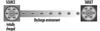
Table 6. Examples of equipment sensitive to electrostatic discharges
|
Sensitive element |
Examples |
|
Source |
An operator touching a door handle or the chassis of a car A |
|
Target |
Electronic components or materials touching a charged operator |
|
Environment |
An explosive mixture ignited by an electrostatic discharge |
Protection of workers
Workers who have reason to believe that they have become electrically charged (for example, when dismounting from a vehicle in dry weather or walking with certain types of shoes), can apply a number of protective measures, such as the following:
- Reduce the current density at the skin level by touching a grounded conductor with a piece of metal such as a key or tool.
- Reduce the peak value of the current by discharging to a dissipating object, if one is available (a table top or special device such as a protective wrist strap with serial resistance).
Protection in explosive atmospheres
In explosive atmospheres, it is the environment itself that is sensitive to electrostatic discharges, and discharges may result in ignition or explosion. Protection in these cases consists of replacing the air, either with a gas mixture whose oxygen content is less than the lower explosive limit, or with an inert gas, such as nitrogen. Inert gas has been used in silos and in reaction vessels in the chemical and pharmaceutical industries. In this case, adequate precautions to assure that workers receive an adequate air supply are needed.
Prevention and Standards
Hazards and Preventive Measures at Electrical Facilities
The many components making up electrical installations exhibit varying degrees of robustness. Regardless of their inherent fragility, however, they must all operate reliably under rigorous conditions. Unfortunately, even under the best circumstances, electrical equipment is subject to failures that may result in human injury or material damage.
Safe operation of electrical installations is the result of good initial design, not the mere retrofitting of safety systems. This is a corollary of the fact that while current flows at the speed of light, all electromechanical and electronic systems exhibit reaction latencies, caused primarily by thermal inertia, mechanical inertia and maintenance conditions. These latencies, whatever their origins, are sufficiently lengthy to allow humans to be injured and equipment damaged (Lee, Capelli-Schellpfeffer and Kelly 1994; Lee, Cravalho and Burke 1992; Kane and Sternheim 1978).
It is essential that equipment be installed and maintained by qualified personnel. Technical measures, it should be emphasized, are necessary both to ensure the safe operation of installations and to protect humans and equipment.
Introduction to electrical hazards
Proper operation of electrical installations requires that machinery, equipment, and electrical circuits and lines be protected from hazards caused by both internal (i.e., arising within the installation) and external factors (Andreoni and Castagna 1983).
Internal causes include:
- overvoltages
- short circuits
- modification of the current’s wave-form
- induction
- interference
- overcurrents
- corrosion, leading to electrical current leakages to ground
- heating of conducting and insulating materials, which may result in operator burns, emissions of toxic gases, component fires and, in flammable atmospheres, explosions
- leaks of insulating fluids, such as oil
- generation of hydrogen or other gases which may lead to the formation of explosive mixtures.
Each hazard-equipment combination requires specific protective measures, some of which are mandated by law or internal technical regulations. Manufacturers have a responsibility to be aware of specific technical strategies capable of reducing risks.
External causes include:
- mechanical factors (falls, bumps, vibration)
- physical and chemical factors (natural or artificial radiation, extreme temperatures, oils, corrosive liquids, humidity)
- wind, ice, lightning
- vegetation (trees and roots, both dry and wet)
- animals (in both urban and rural settings); these may damage the power-line insulation, and so cause short circuits or false contacts
and, last but not least,
- adults and children who are careless, reckless or ignorant of risks and operating procedures.
Other external causes include electromagnetic interference by sources such as high-voltage lines, radio receivers, welding machines (capable of generating transient overvoltages) and solenoids.
The most frequently encountered causes of problems arise from malfunctioning or non-standard:
- mechanical, thermal or chemical protective equipment
- ventilation systems, machine cooling systems, equipment, lines or circuits
- coordination of insulators used in different parts of the plant
- coordination of fuses and automatic circuit-breakers.
A single fuse or automatic circuit-breaker is incapable of providing adequate protection against overcurrent on two different circuits. Fuses or automatic circuit breakers can provide protection against phase-neutral failures, but protection against phase-ground failures requires automatic residual-current circuit-breakers.
- use of voltage relays and dischargers to coordinate protective systems
- sensors and mechanical or electrical components in the installation’s protective systems
- separation of circuits at different voltages (adequate air gaps must be maintained between conductors; connections should be insulated; transformers should be equipped with grounded shields and suitable protection against overvoltage, and have fully segregated primary and secondary coils)
- colour codes or other suitable provisions to avoid misidentification of wires
- mistaking the active phase for a neutral conductor results in electrification of the equipment’s external metallic components
- protective equipment against electromagnetic interference.
These are particularly important for instrumentation and lines used for data transmission or the exchange of protection and/or controlling signals. Adequate gaps must be maintained between lines, or filters and shields used. Fibre-optic cables are sometimes used for the most critical cases.
The risk associated with electrical installations increases when the equipment is subjected to severe operating conditions, most commonly as a result of electrical hazards in humid or wet environments.
The thin liquid conductive layers that form on metallic and insulating surfaces in humid or wet environments create new, irregular and dangerous current pathways. Water infiltration reduces the efficiency of insulation, and, should water penetrate the insulation, it can cause current leakages and short circuits. These effects not only damage electrical installations but greatly increase human risks. This fact justifies the need for special standards for work in harsh environments such as open-air sites, agricultural installations, construction sites, bathrooms, mines and cellars, and some industrial settings.
Equipment providing protection against rain, side-splashes or full immersion is available. Ideally, the equipment should be enclosed, insulated and corrosion proof. Metallic enclosures must be grounded. The mechanism of failure in these wet environments is the same as that observed in humid atmospheres, but the effects may be more severe.
Electrical hazards in dusty atmospheres
Fine dusts that enter machines and electrical equipment cause abrasion, particularly of mobile parts. Conducting dusts may also cause short circuits, while insulating dusts may interrupt current flow and increase contact resistance. Accumulations of fine or coarse dusts around equipment cases are potential humidity and water reservoirs. Dry dust is a thermal insulator, reducing heat dispersion and increasing local temperature; this may damage electrical circuits and cause fires or explosions.
Water- and explosion-proof systems must be installed in industrial or agricultural sites where dusty processes are carried out.
Electrical hazards in explosive atmospheres or at sites containing explosive materials
Explosions, including those of atmospheres containing explosive gases and dusts, may be triggered by opening and closing live electrical circuits, or by any other transient process capable of generating sparks of sufficient energy.
This hazard is present in sites such as:
- mines and underground sites where gases, especially methane, may accumulate
- chemical industries
- lead-battery storage rooms, where hydrogen may accumulate
- the food industry, where natural organic powders may be generated
- the synthetic materials industry
- metallurgy, especially that involving aluminium and magnesium.
Where this hazard is present, the number of electrical circuits and equipment should be minimized—for example, by removing electrical motors and transformers or replacing them with pneumatic equipment. Electrical equipment which cannot be removed must be enclosed, to avoid any contact of flammable gases and dusts with sparks, and a positive-pressure inert-gas atmosphere maintained within the enclosure. Explosion-proof enclosures and fireproof electrical cables must be used where there is the possibility of explosion. A full range of explosion-proof equipment has been developed for some high-risk industries (e.g., the oil and chemical industries).
Because of the high cost of explosion-proof equipment, plants are commonly divided into electrical hazard zones. In this approach, special equipment is used in high-risk zones, while a certain amount of risk is accepted in others. Various industry-specific criteria and technical solutions have been developed; these usually involve some combination of grounding, component segregation and the installation of zoning barriers.
Equipotential Bonding
If all the conductors, including the earth, that can be touched simultaneously were at the same potential, there would be no danger to humans. Equipotential bonding systems are an attempt to achieve this ideal condition (Andreoni and Castagna 1983; Lee, Cravalho and Burke 1992).
In equipotential bonding, every exposed conductor of non-transmission electrical equipment and every accessible extraneous conductor in the same site are connected to a protective grounded conductor. It should be recalled that while the conductors of non-transmission equipment are dead during normal operation, they may become live following insulation failure. By decreasing the contact voltage, equipotential bonding prevents metallic components from reaching voltages that are hazardous to both humans and equipment.
In practice, it may prove necessary to connect the same machine to the equipotential bonding grid at more than one point. Areas of poor contact, due, for example, to the presence of insulators such as lubricants and paint, should be carefully identified. Similarly, it is good practice to connect all the local and external service piping (e.g., water, gas and heating) to the equipotential bonding grid.
Grounding
In most cases, it is necessary to minimize the voltage drop between the installation’s conductors and the earth. This is accomplished by connecting the conductors to a grounded protective conductor.
There are two types of ground connections:
- functional grounds—for example, grounding the neutral conductor of a three-phase system, or the midpoint of a transformer’s secondary coil
- protective grounds—for example, grounding every conductor on a piece of equipment. The object of this type of grounding is to minimize conductor voltages by creating a preferential path for fault currents, especially those currents likely to affect humans.
Under normal operating conditions, no current flows through ground connections. In the event of accidental activation of the circuit, however, the current flow through the low-resistance grounding connection is high enough to melt the fuse or the ungrounded conductors.
The maximum fault voltage in equipotential grids allowed by most standards is 50 V for dry environments, 25 V for wet or humid environments and 12 V for medical laboratories and other high-risk environments. Although these values are only guidelines, the necessity of ensuring adequate grounding in workplaces, public spaces and especially residences, should be emphasized.
The efficiency of grounding depends primarily on the existence of high and stable ground leakage currents, but also on adequate galvanic coupling of the equipotential grid, and the diameter of the conductors leading to the grid. Because of the importance of ground leakage, it must be evaluated with great accuracy.
Ground connections must be as reliable as equipotential grids, and their proper operation must be verified on a regular basis.
As the earth resistance increases, the potential of both the grounding conductor and the earth around the conductor approaches that of the electrical circuit; in the case of the earth around the conductor, the potential generated is inversely proportional to the distance from the conductor. In order to avoid dangerous step voltages, ground conductors must be properly shielded and set in the ground at adequate depths.
As an alternative to equipment grounding, standards allow for the use of double-insulated equipment. This equipment, recommended for use in residential settings, minimizes the chance of insulation failure by providing two separate insulation systems. Double-insulated equipment cannot be relied upon to adequately protect against interface failures such as those associated with loose but live plugs, since some countries’ plug and wall-socket standards do not address the use of such plugs.
Circuit-breakers
The surest method of reducing electrical hazards to humans and equipment is to minimize the duration of the fault current and voltage increase, ideally before the electrical energy has even begun to increase. Protective systems in electrical equipment usually incorporate three relays: a residual-current relay to protect against failure towards ground, a magnetic relay and a thermal relay to protect against overloads and short circuits.
In residual-current circuit-breakers, the conductors in the circuit are wound around a ring which detects the vector sum of the currents entering and exiting the equipment to be protected. The vector sum is equal to zero during normal operation, but equals the leakage current in cases of failure. When the leakage current reaches the breaker’s threshold, the breaker is tripped. Residual-current circuit-breakers can be tripped by currents as low as 30 mA, with latencies as low as 30 ms.
The maximum current that can be safely carried by a conductor is a function of its cross-sectional area, insulation and installation. Overheating will result if the maximum safe load is exceeded or if heat dissipation is limited. Overcurrent devices such as fuses and magneto-thermal circuit-breakers automatically break the circuit if excessive current flow, ground faults, overloading or short circuits occur. Overcurrent devices should interrupt the current flow when it exceeds the conductor’s capacity.
Selection of protective equipment capable of protecting both personnel and equipment is one of the most important issues in the management of electrical installations and must take into account not only the current-carrying capacity of conductors but also the characteristics of the circuits and the equipment connected to them.
Special high-capacity fuses or circuit-breakers must be used on circuits carrying very high current loads.
Fuses
Several types of fuse are available, each designed for a specific application. Use of the wrong type of fuse or of a fuse of the wrong capacity may cause injury and damage equipment. Overfusing frequently results in overheated wiring or equipment, which in turn may cause fires.
Before replacing fuses, lock out, tag and test the circuit, to verify that the circuit is dead. Testing can save lives. Next, identify the cause of any short circuits or overloads, and replace blown fuses with fuses of the same type and capacity. Never insert fuses in a live circuit.
Circuit-breakers
Although circuit-breakers have long been used in high-voltage circuits with large current capacities, they are increasingly used in many other kinds of circuits. Many types are available, offering a choice of immediate and delayed onset and manual or automatic operation.
Circuit-breakers fall into two general categories: thermal and magnetic.
Thermal circuit-breakers react solely to a rise of temperature. Variations in the circuit-breaker’s ambient temperature will therefore affect the point at which the breaker is tripped.
Magnetic circuit-breakers, on the other hand, react solely to the amount of current passing through the circuit. This type of breaker is preferable where wide temperature fluctuations would require overrating the circuit-breaker, or where the breaker is frequently tripped.
In the case of contact with lines carrying high current loads, protective circuits cannot prevent personal injury or equipment damage, as they are designed only to protect power-lines and systems from excess current flow caused by faults.
Because of the resistance of the contact with the earth, the current passing through an object simultaneously contacting the line and the earth will usually be less than the tripping current. Fault currents flowing through humans may be further reduced by body resistance to the point where they do not trip the breaker, and are therefore extremely dangerous. It is virtually impossible to design a power system that would prevent injury or damage to any object that faults the power lines while remaining a useful energy transmission system, as the trip thresholds for the relevant circuit protection devices are well above the human hazard level.
Standards and Regulations
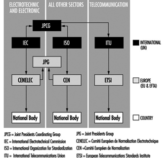
The framework of international standards and regulations is illustrated in figure 1 (Winckler 1994). The rows correspond to the geographic scope of the standards, either worldwide (international), continental (regional) or national, while the columns correspond to the standards’ fields of application. The IEC and the International Organization for Standardization (ISO) both share an umbrella structure, the Joint Presidents Coordinating Group (JPCG); the European equivalent is the Joint Presidents Group (JPG).
Figure 1. The framework of international standards and regulations
Each standardization body holds regular international meetings. The composition of the various bodies reflects the development of standardization.
The Comité européen de normalisation électrotechnique (CENELEC) was created by the electrical engineering committees of the countries signing the 1957 Rome Treaty establishing the European Economic Community. The six founding members were later joined by the members of the European Free Trade Association (EFTA), and CENELEC in its present form dates from 13 February, 1972.
In contrast to the International Electrotechnical Commission (IEC), CENELEC focuses on the implementation of international standards in member countries rather than on the creation of new standards. It is particularly important to recall that while the adoption of IEC standards by member countries is voluntary, adoption of CENELEC standards and regulations is obligatory in the European Union. Over 90% of CENELEC standards are derived from IEC standards, and over 70% of them are identical. CENELEC’s influence has also attracted the interest of Eastern European countries, most of which became affiliated members in 1991.
The International Association for Testing and Materials, the forerunner of the ISO, as it is known today, was founded in 1886 and was active until The First World War, after which it ceased to function as an international association. Some national organizations, like the American Society for Testing and Materials (ASTM), survived. In 1926, the International Standards Association (ISA) was founded in New York and was active until The Second World War. The ISA was replaced in 1946 by the ISO, which is responsible for all fields except electrical engineering and telecommunications. The Comité européen de normalisation (CEN) is the European equivalent of the ISO and has the same function as CENELEC, although only 40% of CEN standards are derived from ISO standards.
The current wave of international economic consolidation creates a need for common technical databases in the field of standardization. This process is presently under way in several parts of the world, and it is likely that new standardization bodies will evolve outside of Europe. CANENA is a regional standardization body created by the North American Free Trade Agreement (NAFTA) countries (Canada, Mexico and the United States). Wiring of premises in the US is governed by the National Electrical Code, ANSI/NFPA 70-1996. This Code is also in use in several other countries in North and South America. It provides installation requirements for premises wiring installations beyond the point of connection to the electric utility system. It covers installation of electric conductors and equipment within or on public and private buildings, including mobil homes, recreational vehicles, and floating buildings, stock yards, carnivals, parking and other lots, and industrial substations. It does not cover installations in ships or watercraft other than floating buildings—railway rolling stop, aircraft, or automotive vehicles. The National Electric Code also does not apply to other areas that are normally regulated by the National Electrical Safety Code, such as installations of communications utility equipment and electric utility installations.
European and American Standards for the Operation of Electrical Installations
The European Standard EN 50110-1, Operation of Electrical Installations (1994a) prepared by CENELEC Task Force 63-3, is the basic document that applies to the operation of and work activities on, with or near electrical installations. The standard sets the minimum requirements for all CENELEC countries; additional national standards are described in separate subparts of the standard (EN 50110-2).
The standard applies to installations designed for the generation, transmission, conversion, distribution and use of electrical power, and operating at commonly encountered voltage levels. Although typical installations operate at low voltages, the standard also applies to extra-low and high-voltage installations. Installations may be either permanent and fixed (e.g., distribution installations in factories or office complexes) or mobile.
Safe operation and maintenance procedures for work on or near electrical installations are set out in the standard. Applicable work activities include non-electrical work such as construction near overhead lines or underground cables, in addition to all types of electrical work. Certain electrical installations, such as those on board aircraft and ships, are not subject to the standard.
The equivalent standard in the United States is the National Electrical Safety Code (NESC), American National Standards Institute (1990). The NESC applies to utility facilities and functions from the point of generation of electricity and communication signals, through the transmission grid, to the point of delivery to a customer’s facilities. Certain installations, including those in mines and ships, are not subject to the NESC. NESC guidelines are designed to ensure the safety of workers engaged in the installation, operation or maintenance of electric supply and communication lines and associated equipment. These guidelines constitute the minimum acceptable standard for occupational and public safety under the specified conditions. The code is not intended as a design specification or an instruction manual. Formally, the NESC must be regarded as a national safety code applicable to the United States.
The extensive rules of both the European and American standards provide for the safe performance of work on electrical installations.
The European Standard (1994a)
Definitions
The standard provides definitions only for the most common terms; further information is available in the International Electrotechnical Commission (1979). For the purposes of this standard, electrical installation refers to all equipment involved in the generation, transmission, conversion, distribution and use of electrical energy. This includes all energy sources, including batteries and capacitors (ENEL 1994; EDF-GDF 1991).
Basic principles
Safe operation: The basic principle of safe work on, with or near an electrical installation is the need to assess the electrical risk before commencing work.
Personnel: The best rules and procedures for work on, with or near electrical installations are of no value if workers are not thoroughly conversant with them and do not comply strictly with them. All personnel involved in work on, with or near an electrical installation shall be instructed in the safety requirements, safety rules and company policies applicable to their work. Where the work is long or complex, this instruction shall be repeated. Workers shall be required to comply with these requirements, rules and instructions.
Organization: Each electrical installation shall be placed under the responsibility of the designated person in control of the electrical installation. In cases of undertakings involving more than one installation, it is essential that the designated persons in control of each installation cooperate with each other.
Each work activity shall be the responsibility of the designated person in control of the work. Where the work comprises sub-tasks, persons responsible for the safety of each sub-task will be designated, each reporting to the coordinator. The same person can act as the designated person in control of the work and the designated person in control of the electrical installation.
Communication: This includes all means of information transmission between persons, i.e., spoken word (including telephones, radio and speech), writing (including fax) and visual means (including instrument panels, video, signals and lights).
Formal notification of all information necessary for the safe operation of the electrical installation, e.g., network arrangements, switchgear status and the position of safety devices, shall be given.
Worksite: Adequate working space, access and lighting shall be provided at electrical installations on, with or near which any work is to be carried out.
Tools, equipment and procedures: Tools, equipment and procedures shall comply with the requirements of relevant European, national and international standards, where these exist.
Drawings and reports: The installation’s drawings and reports shall be up to date and readily available.
Signage: Adequate signage drawing attention to specific hazards shall be displayed as needed when the installation is operating and during any work.
Standard operating procedures
Operating activities: Operating activities are designed to change the electrical state of an electrical installation. There are two types:
- operations intended to modify the electrical state of an electrical installation, e.g., in order to use equipment, connect, disconnect, start or stop an installation or section of an installation to carry out work. These activities may be carried out locally or by remote control.
- disconnecting before or reconnecting after dead-working, to be carried out by qualified or trained workers.
Functional checks: This includes measurement, testing and inspection procedures.
Measurement is defined as the entire range of activities used to collect physical data in electrical installations. Measurement shall be carried out by qualified professionals.
Testing includes all activities designed to verify the operation or electrical, mechanical or thermal condition of an electrical installation. Testing shall be carried out by qualified workers.
Inspection is verification that an electrical installation conforms to applicable specified technical and safety regulations.
Work procedures
General: The designated person in control of the electrical installation and the designated person in control of the work shall both ensure that workers receive specific and detailed instructions before starting the work, and on its completion.
Before the start of work, the designated person in control of the work shall notify the designated person in control of the electrical installation of the nature, site and consequences to the electrical installation of the intended work. This notification shall be given preferably in writing, especially when the work is complex.
Work activities can be divided into three categories: dead-working, live-working and work in the vicinity of live installations. Measures designed to protect against electrical shocks, short circuits and arcing have been developed for each type of work.
Induction: The following precautions shall be taken when working on electrical lines subject to current induction:
- grounding at appropriate intervals; this reduces the potential between conductors and earth to a safe level
- equipotential bonding of the worksite; this prevents workers from introducing themselves into the induction loop.
Weather conditions: When lightning is seen or thunder heard, no work shall be started or continued on outdoor installations or on indoor installations directly connected to overhead lines.
Dead-working
The following basic work practices will ensure that the electrical installations at the worksite remain dead for the duration of the work. Unless there are clear contraindications, the practices should be applied in the order listed.
Complete disconnection: The section of the installation in which the work is to be carried out shall be isolated from all sources of current supply, and secured against reconnection.
Securing against reconnection: All circuit-breaking devices used to isolate the electrical installation for the work shall be locked out, preferably by locking the operating mechanism.
Verification that the installation is dead: The absence of current shall be verified at all poles of the electrical installation at or as near as practicable to the worksite.
Grounding and short-circuiting: At all high- and some low-voltage worksites, all parts to be worked on shall be grounded and short-circuited after they have been disconnected. Grounding and short-circuiting systems shall be connected to the earth first; the components to be grounded must be connected to the system only after it has been earthed. As far as practical, the grounding and short-circuiting systems shall be visible from the worksite. Low- and high-voltage installations have their own specific requirements. At these types of installation, all sides of the worksites and all conductors entering the site must be grounded and short-circuited.
Protecting against adjacent live parts: Additional protective measures are necessary if parts of an electrical installation in the vicinity of the worksite cannot be made dead. Workers shall not commence work before receiving permission to do so from the designated person in control of the work, who in turn must receive authorization from the designated person in control of the electrical installation. Once the work has been completed, workers shall leave the worksite, tools and equipment shall be stored, and grounding and short-circuiting systems removed. The designated person in control of the work shall then notify the designated person in control of the electrical installation that the installation is available for reconnection.
Live-working
General: Live-working is work carried out within a zone in which there is current flow. Guidance for the dimensions of the live-working zone can be found in standard EN 50179. Protective measures designed to prevent electric shocks, arcing and short circuits shall be applied.
Training and qualification: Specific training programmes shall be established to develop and maintain the ability of qualified or trained workers to perform live-working. After completing the programme, workers will receive a qualification rating and authorization to perform specific live-work on specific voltages.
Maintenance of qualifications: The ability to carry out live-working shall be maintained by either practice or new training.
Work techniques: Currently, there are three recognized techniques, distinguished by their applicability to different types of live parts and the equipment required to prevent electric shocks, arcing and short circuits:
- hot-stick working
- insulating-glove working
- bare-hand working.
Each technique requires different preparation, equipment and tools, and selection of the most appropriate technique will depend on the characteristics of the work in question.
Tools and equipment: The characteristics, storage, maintenance, transportation and inspection of tools, equipment and systems shall be specified.
Weather conditions: Restrictions apply to live-working in adverse weather conditions, since insulating properties, visibility and worker mobility are all reduced.
Work organization: The work shall be adequately prepared; written preparation shall be submitted in advance for complex work. The installation in general, and the section where the work is to be carried out in particular, shall be maintained in a condition consistent with the preparation required. The designated person in control of the work shall inform the designated person in control of the electrical installation of the nature of the work, the site in the installation at which the work will be performed, and the estimated duration of the work. Before work begins, workers shall have the nature of the work, the relevant safety measures, the role of each worker, and the tools and equipment to be used explained to them.
Specific practices exist for extra-low-voltage, low-voltage, and high-voltage installations.
Work in the vicinity of live parts
General: Work in the vicinity of live parts with nominal voltages above 50 VAC or 120 VDC shall be performed only when safety measures have been applied to ensure that live parts cannot be touched or that the live zone cannot be entered. Screens, barriers, enclosures or insulating coverings may be used for this purpose.
Before the work starts, the designated person in control of the work shall instruct the workers, particularly those unfamiliar with work in the vicinity of live parts, on the safety distances to be observed on the worksite, the principal safety practices to follow, and the need for behaviour that ensures the safety of the entire work crew. Worksite boundaries shall be precisely defined and marked and attention drawn to unusual working conditions. This information shall be repeated as needed, particularly after changes in working conditions.
Workers shall ensure that no part of their body nor any object enters the live zone. Particular care shall be taken when handling long objects, for example, tools, cable ends, pipes and ladders.
Protection by screens, barriers, enclosures or insulating coverings: The selection and installation of these protective devices shall ensure sufficient protection against predictable electrical and mechanical stressors. The equipment shall be suitably maintained and kept secured during the work.
Maintenance
General: The purpose of maintenance is to maintain the electrical installation in the required condition. Maintenance may be preventive (i.e., carried out on a regular basis to prevent breakdowns and keep equipment in working order) or corrective (i.e., carried out to replace defective parts).
Maintenance work can be divided into two risk categories:
- work involving the risk of electrical shock, where procedures applicable to live-working and work in the vicinity of live parts must be followed
- work where equipment design allows some maintenance work to be performed in the absence of full live-working procedures
Personnel: Personnel who are to carry out the work shall be adequately qualified or trained and shall be provided with appropriate measuring and testing tools and devices.
Repair work: Repair work consists of the following steps: fault location; fault rectification and/or replacement of components; recommissioning of the repaired section of the installation. Each of these steps may require specific procedures.
Replacement work: In general, fuse replacement in high-voltage installations shall be performed as dead-work. Fuse replacement shall be performed by qualified workers following appropriate work procedures. The replacement of lamps and removable parts such as starters shall be carried out as dead-work. In high-voltage installations, repair procedures shall also apply to replacement work.
Training of Personnel about Electrical Hazards
Effective work organization and safety training is a key element in every successful organization, prevention programme and occupational health and safety programme. Workers must have proper training to do their jobs safely and efficiently.
The responsibility for implementing employee training rests with management. Management must recognize that employees must perform at a certain level before the organization can achieve its objectives. In order to achieve these levels, worker training policies and, by extension, concrete training programmes must be established. Programmes should include training and qualification phases.
Live-working programmes should include the following elements:
Training: In some countries, programmes and training facilities must be formally approved by a live-working committee or similar body. Programmes are based primarily on practical experience, complemented by technical instruction. Training takes the form of practical work on indoor or outdoor model installations similar to those on which actual work is to be performed.
Qualifications: Live-working procedures are very demanding, and it is essential to use the right person at the right place. This is most easily achieved if qualified personnel of different skill levels are available. The designated person in control of the work should be a qualified worker. Where supervision is necessary, it too should be carried out by a qualified person. Workers should work only on installations whose voltage and complexity corresponds to their level of qualification or training. In some countries, qualification is regulated by national standards.
Finally, workers should be instructed and trained in essential life-saving techniques. The reader is referred to the chapter on first-aid for further information.
" DISCLAIMER: The ILO does not take responsibility for content presented on this web portal that is presented in any language other than English, which is the language used for the initial production and peer-review of original content. Certain statistics have not been updated since the production of the 4th edition of the Encyclopaedia (1998)."