- You are here:
-
Home

- k2 Feed
General Profile
Overview of the Sector
The beverage industry consists of two major categories and eight sub-groups. The non-alcoholic category is comprised of soft drink syrup manufacture; soft drink and water bottling and canning; fruit juices bottling, canning and boxing; the coffee industry and the tea industry. Alcoholic beverage categories include distilled spirits, wine and brewing.
Evolution of the industry
Although many of these beverages, including beer, wine and tea, have been around for thousands of years, the industry has developed only over the past few centuries.
The beverage products industry, viewed as an aggregate group, is highly fragmented. This is evident by the number of manufacturers, methods of packaging, production processes and final products. The soft drink industry is the exception to the rule, as it is quite concentrated. Although the beverage industry is fragmented, ongoing consolidation since the 1970s is changing that.
Since the early 1900s beverage companies have evolved from regional firms that mainly produced goods for local markets, to today’s corporate giants that make products for international markets. This shift began when companies in this manufacturing sector adopted mass production techniques that let them expand. Also during this time period there were advances in product packaging and processes that greatly increased product shelf life. Air-tight containers for tea prevented absorption of moisture, which is the principle cause of loss of flavour. In addition, the advent of refrigeration equipment enabled lager beers to be brewed during the summer months.
Economic importance
The beverage industry employs several million people worldwide, and each type of beverage grosses billions of dollars in revenue each year. Indeed, in several small, developing countries, the production of coffee is the major support of the entire economy.
Characteristics of the Workforce
Though the ingredients and production of beverages vary, generally the characteristics of those employed in this industry have many commonalties. The process of harvesting raw materials, whether they be coffee beans, barley, hops or grapes, employs low-income, unskilled individuals or families. In addition to being their main source of income, the harvest determines a large part of their culture and lifestyle.
In contrast, the processing of the product involves automated and mechanized operations, usually employing a semi-skilled, blue-collar workforce. In the production facility and warehouse areas, some of the common jobs include packaging and filling machine operator, fork-lift operator, mechanic and manual labourer. The training for these positions is completed onsite with extensive on-the-job instruction. As technology and automation evolve, the workforce diminishes in number and technical training becomes more important. This semi-skilled manufacturing workforce is usually supported by a highly skilled technical group consisting of industrial engineers, manufacturing managers, cost accountants and quality assurance/food safety technicians.
The beverage industry for the most part distributes its products to wholesalers using common carriers. However, soft drink manufacturers usually employ drivers to deliver their products directly to individual retailers. These drivers-salesworkers account for about one-seventh of the workers in the soft drink industry.
The more health-conscious atmosphere in Europe and North America in the 1990s has led to a flat market in the alcoholic beverage industry, with demand shifting to non-alcoholic beverages. Both alcoholic and non-alcoholic beverages, however, are expanding considerably in developing nations in Asia, South America and to some extent Africa. Because of this expansion, numerous local jobs are being created to meet production and distribution needs.
Moving Parts of Machines
This article discusses situations and chains of events leading to accidents attributable to contact with the moving part of machines. People who operate and maintain machinery run the risk of being involved in serious accidents. US statistics suggest that 18,000 amputations and over 800 fatalities in the United States each year are assignable to such causes. According to the US National Institute for Occupational Safety and Health (NIOSH), the “caught in, under, or between” category of injuries in their classification ranked highest among the most important kinds of occupational injuries in 1979. Such injuries generally involved machines (Etherton and Myers 1990). “Contact with moving machine part” has been reported as the principal injury event in just over 10% of occupational accidents ever since this category was introduced into Swedish occupational-injury statistics in 1979.
Most machines have moving parts that can cause injury. Such moving parts may be found at the point of operation where work is performed on the material, such as where cutting, shaping, boring or deforming takes place. They may be found in the apparatus which transmits energy to the parts of the machine carrying out the work, such as flywheels, pulleys, connecting rods, couplers, cams, spindles, chains, cranks and gears. They may be found in other moving parts of the machine such as wheels on mobile equipment, gear motors, pumps, compressors and so forth. Hazardous machine movements can also be found among other sorts of machinery, especially in the auxiliary pieces of equipment which handle and transport such loads as work pieces, materials, waste or tools.
All parts of a machine that move in the course of the performance of work may contribute to accidents causing injury and damages. Both rotating and linear machine movements, as well as their sources of power, can be dangerous:
Rotating motion. Even smooth rotating shafts can grip an item of clothing and, for example, draw a person’s arm into a hazardous position. The danger in a rotating shaft increases if it has projecting parts or uneven or sharp surfaces, such as adjusting screws, bolts, slits, notches or cutting edges. Rotating machine parts give rise to “nip points” in three different ways:
- There are the points between two rotating parts that rotate in opposite directions and have parallel axes, such as gears or cog-wheels, carriage rollers or mangles.
- There are the points of contact between rotating parts and parts in linear movement, such as found between a power-transmission belt and its pulley, a chain and a sprocket, or a rack and pinion.
- Rotating machine movements can give rise to the risk of cuts and crushing injuries when they take place in close proximity to stationary objects—this sort of condition exists between a worm conveyor and its housing, between the spokes of a wheel and the machine bed, or between a grinding wheel and a tool jig.
Linear movements. Vertical, horizontal and reciprocating motion can cause injury in several ways: a person may receive a shove or blow from a machine part, and may be caught between the machine part and some other object, or may be cut by a sharp edge, or sustain a nip injury by being trapped between the moving part and another object (figure 1).
Figure 1. Examples of mechanical movements that can injure a person

Power sources. Frequently, external sources of power are employed to run a machine which may involve considerable quantities of energy. These include electric, steam, hydraulic, pneumatic and mechanical power systems, all of which, if released or uncontrolled, can give rise to serious injuries or damage. A study of accidents that occurred over one year (1987 to 1988) among farmers in nine villages in northern India showed that fodder-cutting machines, all otherwise of the same design, are more dangerous when powered by a motor or tractor. The relative frequency of accidents involving more than a minor injury (per machine) was 5.1 per thousand for manual cutters and 8.6 per thousand for powered cutters (Mohan and Patel 1992).
Injuries Associated with Machine Movements
Since the forces associated with machine movements are often quite large, it can be presumed that the injuries to which they give rise will be serious. This presumption is confirmed by several sources. “Contact with moving machinery or material being machined” accounted for only 5% of all occupational accidents but for as much as 10% of fatal and major accidents (fractures, amputations and so on) according to British statistics (HSE 1989). Studies of two vehicle-manufacturing workplaces in Sweden point in the same direction. Accidents caused by machine movements gave rise to twice the number of days of sick leave, as measured by median values, compared to non-machine-related accidents. Machine-related accidents also differed from other accidents with regard to part of the body injured: The results indicated that 80% of the injuries sustained in “machine” accidents were to the hands and fingers, while the corresponding proportion for “other” accidents was 40% (Backström and Döös 1995).
The risk situation at automated installations has turned out to be both different (in terms of type of accident, sequence of events and degree of injury severity) and more complicated (both in technical terms and with regard to the need for specialized skills) than at installations where conventional machinery is used. The term automated is herein meant to refer to equipment which, without the direct intervention of a human being, can either initiate a machine movement or change its direction or function. Such equipment requires sensor devices (e.g., position sensors or microswitches) and/or some form of sequential controls (e.g., a computer program) to direct and monitor their activities. Over recent decades, a programmable logic controller (PLC) has been increasingly employed as the control unit in production systems. Small computers are now the most common means used for controlling production equipment in the industrialized world, while other means of control, such as electro-mechanical units, are becoming less and less common. In the Swedish manufacturing industry, the use of numerically controlled (NC) machines increased by 11 to 12% per year over the 1980s (Hörte and Lindberg 1989). In modern industrial production, being injured by “moving parts of machines” is increasingly becoming equivalent to being injured by “computer-controlled machine movements”.
Automated installations are found in more and more sectors of industry, and they have an increasing number of functions. Stores management, materials handling, processing, assembly and packaging are all being automated. Series production has come to resemble process production. If the feeding, machining and ejection of work pieces are mechanized, the operator no longer needs to be in the risk zone during the course of regular, undisturbed production. Research studies of automated manufacturing have shown that accidents occur primarily in the handling of disturbances affecting production. However, people can also get in the way of machine movements in performing other tasks, such as cleaning, adjusting, resetting, controlling and repairing.
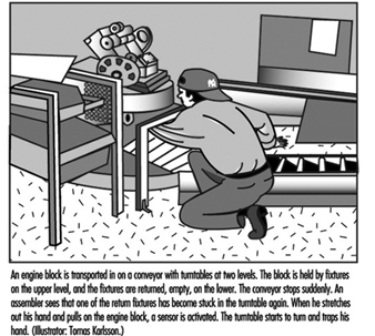
When production is automated and the process is no longer under the direct control of the human being, the risk of unexpected machine movements increases. Most operators who work with groups or lines of inter-linked machines have experienced such unexpected machine movements. Many automation accidents occur as a result of just such movements. An automation accident is an accident in which the automatic equipment controlled (or should have controlled) the energy giving rise to the injury. This means that the force which injures the person comes from the machine itself (e.g., the energy of a machine movement). In a study of 177 automation accidents in Sweden, it was found that injury was caused by the “unexpected start” of a part of a machine in 84% of cases (Backström and Harms-Ringdahl 1984). A typical example of an injury caused by a computer-controlled machine movement is shown in figure 2.
Figure 2. A typical example of an injury caused by a computer-controlled machine movement
One of the studies referred to above (Backström and Döös 1995) showed that automatically controlled machine movements were causally linked to longer periods of sick leave than injuries due to other kinds of machine movements, the median value being four times higher at one of the workplaces. The injury pattern of automation accidents was similar to that for other machine accidents (mainly involving hands and fingers), but the tendency was for the former kind of injuries to be more serious (amputations, crushes and fractures).
Computer control, like manual, has weaknesses from the perspective of reliability. There is no guarantee that a computer program will operate without error. The electronics, with their low signal levels, may be sensitive to interference if not properly protected, and the consequences of resultant failures are not always possible to predict. Furthermore, programming changes are often left undocumented. One method used to compensate for this weakness is, for example, by operating “double” systems in which there are two independent chains of functional components and a method for monitoring such that both chains display the same value. If the systems display different values, this indicates a failure in one of them. But there is a possibility that both chains of components may suffer from the same fault and that they both can be put out of order by the same disturbance, thereby giving a false positive reading (as both systems agree). However, in only a few of the cases investigated has it been possible to trace an accident to computer failure (see below), despite the fact that it is common for a single computer to control all the functions of an installation (even the stopping of a machine as a result of the activation of a safety device). As an alternate, consideration may be given to providing a tried-and-tested system with electro-mechanical components for safety functions.
Technical Problems
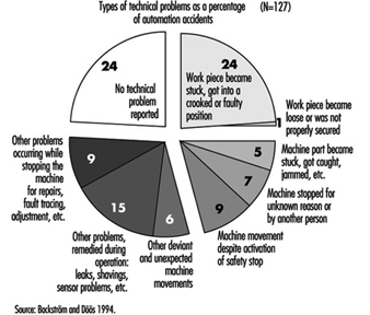
In general, it can be said that a single accident has many causes, including technical, individual, environmental and organizational ones. For preventive purposes, an accident is best looked at not as an isolated event, but as a sequence of events or a process (Backström 1996). In the case of automation accidents, it has been shown that technical problems are frequently part of such a sequence and occur either at one of the early stages of the process or close to the injury event of the accident. Studies in which technical problems involved in automation accidents have been examined suggest that these lie behind 75 to 85% of the accidents. At the same time, in any specific case, there are usually other causes, such as those of an organizational nature. Only in one-tenth of cases has it been found that the direct source of the energy giving rise to an injury could be attributed to technical failure—for example, a machine movement taking place despite the machine’s being in the stop position. Similar figures have been reported in other studies. Usually, a technical problem led to trouble with the equipment, so that the operator had to switch tasks (e.g., to re-position a part that was in a crooked position). The accident then occurred during the implementation of the task, prompted by the technical failure. A quarter of the automation accidents were preceded by a disturbance in the materials flow such as a part becoming stuck or getting into a crooked or otherwise faulty position (see figure 3).
Figure 3. Types of technical problems involved in automation accidents (number of accidents =127)
In a study of 127 accidents involving automation, 28 of these accidents, described in figure 4, were further investigated to determine the types of technical problems which were involved as causal factors (Backström and Döös, in press). The problems specified in the accident investigations were most frequently caused by jammed, defective or worn-out components. In two cases, a problem was caused by a computer-program error, and in one by electromagnetic interference. In more than half of the cases (17 out of 28), faults had been present for some time but not remedied. Only in 5 of the 28 cases where a technical failure or deviation was referred to, had the defect not manifested itself previously. Some faults had been repaired only to reappear later. Certain defects had been present right from the time of installation, while others resulted from wear and the impact of the environment.
The proportion of automation accidents occurring in the course of the correction of a disturbance to production comes to between one-third and two-thirds of all cases, according to most studies. In other words, there is general agreement that handling production disturbances is a hazardous occupational task. The variation in the extent to which such accidents occur has many explanations, among them those related to the type of production and to how occupational tasks are classified. In some studies of disturbances, only problems and machine stops in the course of regular production have been considered; in others, a wider range of problems have been treated—for example, those involved in the setting up of work.
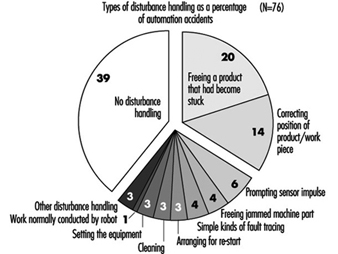
A very important measure in the prevention of automation accidents is to prepare procedures for removing the causes of production disturbances so that they are not repeated. In a specialized study of production disturbances at time of accident (Döös and Backström 1994), it was found that the most common task to which disturbances gave rise was the freeing or the correcting of the position of a work piece that had become stuck or wrongly placed. This type of problem initiated one of two rather similar sequences of events: (1) the part was freed and came into its correct position, the machine received an automatic signal to start, and the person was injured by the machine movement initiated, (2) there was not time for the part to be freed or repositioned before the person was injured by a machine movement that came unexpectedly, more quickly or was of greater force than the operator expected. Other disturbance-handling involved prompting a sensor impulse, freeing a jammed machine part, carrying out simple kinds of fault tracing, and arranging for restart (see figure 4).
Figure 4. Type of disturbance handling at time of accident (number of accidents =76)
Worker Safety
The categories of personnel which tend to be injured in automation accidents depend on how work is organized—that is, on which occupational group performs the hazardous tasks. In practice, this is a matter of which person at the workplace is assigned to deal with problems and disturbances on a routine basis. In modern Swedish industry, active interventions are usually demanded from the persons operating the machine. This is why, in the previously mentioned vehicle-manufacturing workplace study in Sweden (Backström and Döös, accepted for publication), it was found that 82% of the people who sustained injuries from automated machines were production workers or operators. Operators also had a higher relative accident frequency (15 automation accidents per 1,000 operators per year) than maintenance workers (6 per 1,000). The findings of studies which indicate that maintenance workers are more affected are at least partly to be explained by the fact that operators are not allowed to enter machining areas in some companies. In organizations with a different type of task distribution, other categories of personnel—setters, for example—may be given the task of solving any production problems that arise.
The most common corrective measure taken in this connection in order to raise the level of personal safety is to protect the person from hazardous machine movements by using some kind of safety device, such as machine guarding. The main principle here is that of “passive” safety—that is, the provision of protection that does not require action on the part of the worker. It is, however, impossible to judge the effectiveness of protective devices without very good acquaintance with the actual work requirements at the machine in question, a form of knowledge which is normally possessed only by machine operators themselves.
There are many factors that can put even what is apparently good machine protection out of action. In order to perform their work, operators may need to disengage or circumvent a safety device. In one study (Döös and Backström 1993), it was found that such disengagement or circumvention had taken place in 12 out of 75 of the automation accidents covered. It is often a matter of the operator’s being ambitious, and no longer willing to accept either production problems or the delay to the production process involved in correcting disturbances in accordance with instructions. One way of avoiding this problem is to make the protective device imperceptible, so that it does not affect the pace of production, product quality or task performance. But this is not always possible; and where there are repeated disturbances to production, even minor inconveniences can prompt people not to utilize safety devices. Again, routines should be made available to remove the causes of production disturbances so that these are not repeated. A lack of a means of confirming that safety devices really function according to specifications is a further significant risk factor. Faulty connections, start signals that remain in the system and later give rise to unexpected starts, build-up in air pressure, and sensors that have come loose may all cause failure of protective equipment.
Summary
As has been shown, technical solutions to problems may give rise to new problems. Although injuries are caused by machine movements, which are essentially technical by nature, this does not automatically mean that the potential for their eradication lies in purely technical factors. Technical systems will continue to malfunction, and people will fail to handle the situations to which these malfunctions give rise. The risks will continue to exist, and can be held in check only by a wide variety of means. Legislation and control, organizational measures at individual companies (in the form of training, safety rounds, risk analysis and the reporting of disturbances and near accidents), and an emphasis on steady, ongoing improvements are all needed as complements to purely technical development.
Hand and Portable Power Tool Safety
Tools are such a common part of our lives that it is sometimes difficult to remember that they may pose hazards. All tools are manufactured with safety in mind, but occasionally an accident may occur before tool-related hazards are recognized. Workers must learn to recognize the hazards associated with the different types of tools and the safety precautions required to prevent those hazards. Appropriate personal protective equipment, such as safety goggles or gloves, should be worn for protection from potential hazards that may be encountered while using portable power tools and hand tools.
Hand Tools
Hand tools are non-powered and include everything from axes to wrenches. The greatest hazards posed by hand tools result from misuse, use of the wrong tool for the job, and improper maintenance. Some of the hazards associated with the use of hand tools include but are not limited to the following:
- Using a screwdriver as a chisel may cause the tip of the screwdriver to break off and fly, hitting the user or other employees.
- If a wooden handle on a tool such as a hammer or an axe is loose, splintered or cracked, the head of the tool may fly off and strike the user or another worker.
- A wrench must not be used if its jaws are sprung, because it might slip.
- Impact tools such as chisels, wedges or drift pins are unsafe if they have mushroomed heads which might shatter on impact, sending sharp fragments flying.
The employer is responsible for the safe condition of tools and equipment provided to employees, but the employees have the responsibility to use and maintain the tools properly. Workers should direct saw blades, knives or other tools away from aisle areas and other employees working in close proximity. Knives and scissors must be kept sharp, as dull tools can be more hazardous than sharp ones. (See figure 1.)
Figure 1. A screwdriver

Safety requires that floors be kept as clean and dry as possible to prevent accidental slips when working with or around dangerous hand tools. Although sparks produced by iron and steel hand tools are not normally hot enough to be sources of ignition, when working with or around flammable materials, spark-resistant tools made from brass, plastic, aluminium or wood may be used to prevent spark formation.
Power Tools
Power tools are hazardous when improperly used. There are several types of power tools, usually categorized according to the power source (electric, pneumatic, liquid fuel, hydraulic, steam and explosive powder actuated). Employees should be qualified or trained in the use of all power tools used in their work. They should understand the potential hazards associated with the use of power tools, and observe the following general safety precautions to prevent those hazards from occurring:
- Never carry a tool by the cord or hose.
- Never yank the cord or the hose to disconnect it from the receptacle.
- Keep cords and hoses away from heat, oil and sharp edges.
- Disconnect tools when they are not in use, before servicing, and when changing accessories such as blades, bits and cutters.
- All observers should stay a safe distance away from the work area.
- Secure work with clamps or a vise, freeing both hands to operate the tool.
- Avoid accidental starting. The worker should not hold a finger on the switch button while carrying a plugged-in tool. Tools which have lock-on controls should be disengaged when power is interrupted so that they do not start up automatically upon restoration of power.
- Tools should be maintained with care and kept sharp and clean for best performance. Instructions in the user’s manual should be followed for lubrication and changing accessories.
- Workers should assure they have good footing and balance when using power tools. Appropriate apparel should be worn, as loose clothing, ties or jewellery can become caught in moving parts.
- All portable electric tools that are damaged shall be removed from use and tagged “Do Not Use” to prevent electrical shock.
Protective Guards
Hazardous moving parts of power tools need to be safeguarded. For example, belts, gears, shafts, pulleys, sprockets, spindles, drums, flywheels, chains or other reciprocating, rotating or moving parts of equipment must be guarded if such parts are exposed to contact by workers. Where necessary, guards should be provided to protect the operator and others with respect to hazards associated with:
- the point of operation
- in-running nip points
- rotating and reciprocating parts
- flying chips and sparks, and mist or spray from metal-working fluids.
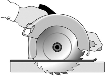
Safety guards must never be removed when a tool is being used. For example, portable circular saws must be equipped with guards. An upper guard must cover the entire blade of the saw. A retractable lower guard must cover the teeth of the saw, except when it makes contact with the work material. The lower guard must automatically return to the covering position when the tool is withdrawn from the work. Note the blade guards in the illustration of a power saw (figure 2).
Figure 2. A circular saw with guard
Safety Switches and Controls
The following are examples of hand-held power tools which must be equipped with a momentary contact “on-off” control switch:
- drills, tappers and fastener drivers
- horizontal, vertical and angle grinders with wheels larger than 2 inches (5.1 cm) in diameter
- disc and belt sanders
- reciprocating and sabre saws.
These tools also may be equipped with a lock-on control, provided that turnoff can be accomplished by a single motion of the same finger or fingers that turn it on.
The following hand-held power tools may be equipped with only a positive “on-off” control switch:
- platen sanders
- disc sanders with discs 2 inches (5.1 cm) or less in diameter
- grinders with wheels 2 inches (5.1 cm) or less in diameter
- routers and planers
- laminate trimmers, nibblers and shears
- scroll saws and jigsaws with blade shanks ¼ inch (0.64 cm) wide or less.
Other hand-held power tools which must be equipped with a constant pressure switch that will shut off the power when the pressure is released include:
- circular saws having a blade diameter greater than 2 inches (5.1 cm)
- chain-saws
- percussion tools without positive accessory-holding means.
Electric Tools
Workers using electric tools must be aware of several dangers. The most serious of these is the possibility of electrocution, followed by burns and slight shocks. Under certain conditions, even a small amount of current can result in fibrillation of the heart which may result in death. A shock also may cause a worker to fall off a ladder or other elevated work surfaces.
To reduce the potential of injury to workers from shock, tools must be protected by at least one of the following means:
- Grounded by a three-wire cord (with a ground wire). Three-wire cords contain two current-carrying conductors and a grounding conductor. One end of the grounding conductor connects to the tool’s metal housing. The other end is grounded through a prong on the plug. Any time an adapter is used to accommodate a two-hole receptacle, the adapter wire must be attached to a known ground. The third prong should never be removed from the plug. (See figure 3.)
- Double insulated. The worker and the tools are protected in two ways: (1) by normal insulation on the wires inside, and (2) by a housing that cannot conduct electricity to the operator in the event of a malfunction.
- Powered by a low-voltage isolation transformer.
- Connected through ground fault circuit interrupters. These are permanent and portable devices which instantaneously disconnect a circuit when it seeks ground through a worker’s body or through grounded objects.

These general safety practices should be followed in using electric tools:
- Electric tools should be operated within their design limitations.
- Gloves and safety footwear are recommended during use of electric tools.
- When not in use, tools should be stored in a dry place.
- Tools should not be used if wires or connectors are frayed, bent or damaged.
- Electric tools should not be used in damp or wet locations.
- Work areas should be well lighted.
Powered Abrasive Wheels
Powered abrasive grinding, cutting, polishing and wire buffing wheels create special safety problems because the wheels may disintegrate and throw off flying fragments.
Before abrasive wheels are mounted, they should be inspected closely and sound (or ring) tested by tapping gently with a light non-metallic instrument to be sure that they are free from cracks or defects. If wheels are cracked or sound dead, they could fly apart in operation and must not be used. A sound and undamaged wheel will give a clear metallic tone or “ring”.
To prevent the wheel from cracking, the user should be sure it fits freely on the spindle. The spindle nut must be tightened enough to hold the wheel in place without distorting the flange. Follow the manufacturer’s recommendations. Care must be taken to assure that the spindle wheel will not exceed the abrasive wheel specifications. Due to the possibility of a wheel disintegrating (exploding) during start-up, the worker should never stand directly in front of the wheel as it accelerates to full operating speed. Portable grinding tools need to be equipped with safety guards to protect workers not only from the moving wheel surface, but also from flying fragments in case of breakage. In addition, when using a powered grinder, these precautions should be observed:
- Always use eye protection.
- Turn off the power when tool is not in use.
- Never clamp a hand-held grinder in a vise.
Pneumatic Tools
Pneumatic tools are powered by compressed air and include chippers, drills, hammers and sanders. Although there are several potential dangers encountered in the use of pneumatic tools, the main one is the danger of getting hit by one of the tool’s attachments or by some kind of fastener the worker is using with the tool. Eye protection is required and face protection is recommended when working with pneumatic tools. Noise is another hazard. Working with noisy tools such as jackhammers requires proper, effective use of appropriate hearing protection.
When using a pneumatic tool, the worker must check to assure that it is fastened securely to the hose to prevent a disconnection. A short wire or positive locking device attaching the air hose to the tool will serve as an added safeguard. If an air hose is more than½ inch (1.27 cm) in diameter, a safety excess flow valve should be installed at the source of the air supply to shut off the air automatically in case the hose breaks. In general, the same precautions should be taken with an air hose that are recommended for electric cords, because the hose is subject to the same kind of damage or accidental striking, and it also presents a tripping hazard.
Compressed-air guns should never be pointed toward anyone. Workers should never “dead-end” the nozzle against themselves or anyone else. A safety clip or retainer should be installed to prevent attachments, such as a chisel on a chipping hammer, from being unintentionally shot from the barrel. Screens should be set up to protect nearby workers from being struck by flying fragments around chippers, riveting guns, air hammers, staplers or air drills.
Airless spray guns that atomize paints and fluids at high pressures (1,000 pounds or more per square inch) must be equipped with automatic or manual visual safety devices that will prevent activation until the safety device is manually released. Heavy jackhammers can cause fatigue and strains which may be reduced by the use of heavy rubber grips that provide a secure handhold. A worker operating a jackhammer must wear safety glasses and safety shoes to protect against injury if the hammer slips or falls. A face shield also should be used.
Fuel-Powered Tools
Fuel-powered tools are usually operated using small gasoline-powered internal combustion motors. The most serious potential dangers associated with the use of fuel-powered tools comes from hazardous fuel vapours that can burn or explode and give off dangerous exhaust fumes. The worker must be careful to handle, transport and store the gasoline or fuel only in approved flammable liquid containers, according to proper procedures for flammable liquids. Before the tank for a fuel-powered tool is refilled, the user must shut down the engine and allow it to cool to prevent accidental ignition of hazardous vapours. If a fuel-powered tool is used inside a closed area, effective ventilation and/or protective equipment is necessary to prevent exposure to carbon monoxide. Fire extinguishers must be available in the area.
Explosive Powder-Actuated Tools
Explosive powder-actuated tools operate like a loaded gun and should be treated with the same respect and precautions. In fact, they are so dangerous that they must be operated only by specially trained or qualified employees. Suitable ear, eye and face protection are essential when using a powder-actuated tool. All powder-actuated tools should be designed for varying powder charges so that the user can select a powder level necessary to do the work without excessive force.
The muzzle end of the tool should have a protective shield or guard centred perpendicularly on the barrel to protect the user from any flying fragments or particles that might create a hazard when the tool is fired. The tool must be designed so that it will not fire unless it has this kind of safety device. To prevent the tool from firing accidentally, two separate motions are required for firing: one to bring the tool into position, and another to pull the trigger. The tools must not be able to operate until they are pressed against the work surface with a force at least 5 pounds greater than the total weight of the tool.
If a powder-actuated tool misfires, the user should wait at least 30 seconds before trying to fire it again. If it still will not fire, the user should wait at least another 30 seconds so that the faulty cartridge is less likely to explode, then carefully remove the load. The bad cartridge should be put in water or otherwise safely disposed of in accordance with employer’s procedures.
If a powder-actuated tool develops a defect during use, it should be tagged and taken out of service immediately until it is properly repaired. Precautions for the safe use and handling of powder-actuated tools include the following:
- Powder-actuated tools should not be used in explosive or flammable atmospheres except upon issuance of a hot-work permit by an authorized person.
- Before using the tool, the worker should inspect it to determine that it is clean, that all moving parts operate freely and that the barrel is free from obstructions.
- The tool should never be pointed at anybody.
- The tool should not be loaded unless it is to be used immediately. A loaded tool should not be left unattended, especially where it may be available to unauthorized persons.
- Hands should be kept clear of the barrel end.
In using powder-actuated tools to apply fasteners, the following safety precautions should be considered:
- Do not fire fasteners into material that would let them pass through to the other side.
- Do not drive fasteners into materials like brick or concrete any closer than 3 inches (7.6 cm) to an edge or corner, or into steel any closer than ½ inch (1.27 cm) to a corner or edge.
- Do not drive fasteners into very hard or brittle material that might chip, shatter or make the fasteners ricochet.
- Use an alignment guide when shooting fasteners into existing holes. Do not drive fasteners into a spalled area caused by an unsatisfactory fastening.
Hydraulic Power Tools
The fluid used in hydraulic power tools must be approved for the expected use and must retain its operating characteristics at the most extreme temperatures to which it will be exposed. The manufacturer’s recommended safe operating pressure for hoses, valves, pipes, filters and other fittings must not be exceeded. Where there is a potential for a leak under high pressure in an area where sources of ignition, such as open flames or hot surfaces, may be present, the use of fire-resistant fluids as the hydraulic medium should be considered.
Jacks
All jacks—lever and ratchet jacks, screw jacks and hydraulic jacks—must have a device that stops them from jacking up too high. The manufacturer’s load limit must be permanently marked in a prominent place on the jack and should not be exceeded. Use wooden blocking under the base if necessary to make the jack level and secure. If the lift surface is metal, place a 1-inch-thick (2.54 cm) hardwood block or equivalent between the underside of the surface and the metal jack head to reduce the danger of slippage. A jack should never be used to support a lifted load. Once the load has been lifted, it should immediately be supported by blocks.
To set up a jack, make certain of the following conditions:
- The base rests on a firm level surface.
- The jack is correctly centred.
- The jack head bears against a level surface.
- The lift force is applied evenly.
Proper maintenance of jacks is essential for safety. All jacks must be inspected before each use and lubricated regularly. If a jack is subjected to an abnormal load or shock, it should be thoroughly examined to make sure it has not been damaged. Hydraulic jacks exposed to freezing temperatures must be filled with an adequate antifreeze liquid.
Summary
Workers who use hand and power tools and who are exposed to the hazards of falling, flying, abrasive and splashing objects and materials, or to hazards of harmful dusts, fumes, mists, vapours or gases, must be provided with the appropriate personal equipment necessary to protect them from the hazard. All hazards involved in the use of power tools can be prevented by workers following five basic safety rules:
- Keep all tools in good condition with regular maintenance.
- Use the right tool for the job.
- Examine each tool for damage before use.
- Operate tools according to the manufacturer’s instructions.
- Select and use appropriate protective equipment.
Employees and employers have a responsibility to work together to maintain established safe work practices. If a an unsafe tool or hazardous situation is encountered, it should be brought to the attention of the proper individual immediately.
Systems Analysis
A system can be defined as a set of interdependent components combined in such a way as to perform a given function under specified conditions. A machine is a tangible and particularly clear-cut example of a system in this sense, but there are other systems, involving men and women on a team or in a workshop or factory, which are far more complex and not so easy to define. Safety suggests the absence of danger or risk of accident or harm. In order to avoid ambiguity, the general concept of an unwanted occurrence will be employed. Absolute safety, in the sense of the impossibility of a more or less unfortunate incident occurring, is not attainable; realistically one must aim for a very low, rather than a zero probability of unwanted occurrences.
A given system may be looked upon as safe or unsafe only with respect to the performance that is actually expected from it. With this in mind, the safety level of a system can be defined as follows: “For any given set of unwanted occurrences, the level of safety (or unsafeness) of a system is determined by the probability of these occurrences taking place over a given period of time”. Examples of unwanted occurrences that would be of interest in the present connection include: multiple fatalities, death of one or several persons, serious injury, slight injury, damage to the environment, harmful effects on living beings, destruction of plants or buildings, and major or limited material or equipment damage.
Purpose of the Safety System Analysis
The object of a system safety analysis is to ascertain the factors which have a bearing on the probability of the unwanted occurrences, to study the way in which these occurrences take place and, ultimately, to develop preventive measures to reduce their probability.
The analytic phase of the problem can be divided into two main aspects:
- identification and description of the types of dysfunction or maladjustment
- identification of the sequences of dysfunctions that combine one with another (or with more “normal” occurrences) to lead ultimately to the unwanted occurrence itself, and the assessment of their likelihood.
Once the various dysfunctions and their consequences have been studied, the system safety analysts can direct their attention to preventive measures. Research in this area will be based directly on earlier findings. This investigation of preventive means follows the two main aspects of the system safety analysis.
Methods of Analysis
System safety analysis may be conducted before or after the event (a priori or a posteriori); in both instances, the method used may be either direct or reverse. An a priori analysis takes place before the unwanted occurrence. The analyst takes a certain number of such occurrences and sets out to discover the various stages that may lead up to them. By contrast, an a posteriori analysis is carried out after the unwanted occurrence has taken place. Its purpose is to provide guidance for the future and, specifically, to draw any conclusions that may be useful for any subsequent a priori analyses.
Although it may seem that an a priori analysis would be very much more valuable than an a posteriori analysis, since it precedes the incident, the two are in fact complementary. Which method is used depends on the complexity of the system involved and on what is already known about the subject. In the case of tangible systems such as machines or industrial facilities, previous experience can usually serve in preparing a fairly detailed a priori analysis. However, even then the analysis is not necessarily infallible and is sure to benefit from a subsequent a posteriori analysis based essentially on a study of the incidents that occur in the course of operation. As to more complex systems involving persons, such as work shifts, workshops or factories, a posteriori analysis is even more important. In such cases, past experience is not always sufficient to permit detailed and reliable a priori analysis.
An a posteriori analysis may develop into an a priori analysis as the analyst goes beyond the single process that led up to the incident in question and starts to look into the various occurrences that could reasonably lead to such an incident or similar incidents.
Another way in which an a posteriori analysis can become an a priori analysis is when the emphasis is placed not on the occurrence (whose prevention is the main purpose of the current analysis) but on less serious incidents. These incidents, such as technical hitches, material damage and potential or minor accidents, of relatively little significance in themselves, can be identified as warning signs of more serious occurrences. In such cases, although carried out after the occurrence of minor incidents, the analysis will be an a priori analysis as regards more serious occurrences that have not yet taken place.
There are two possible methods of studying the mechanism or logic behind the sequence of two or more events:
- The direct, or inductive, method starts with the causes in order to predict their effects.
- The reverse, or deductive, method looks at the effects and works backwards to the causes.
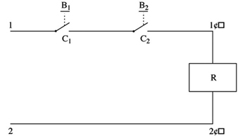
Figure 1 is a diagram of a control circuit requiring two buttons (B1 and B2) to be pressed simultaneously in order to activate the relay coil (R) and start the machine. This example may be used to illustrate, in practical terms, the direct and reverse methods used in system safety analysis.
Figure 1. Two-button control circuit
Direct method
In the direct method, the analyst begins by (1) listing faults, dysfunctions and maladjustments, (2) studying their effects and (3) determining whether or not those effects are a threat to safety. In the case of figure 1, the following faults may occur:
- a break in the wire between 2 and 2´
- unintentional contact at C1 (or C2) as a result of mechanical blocking
- accidental closing of B1 (or B2)
- short circuit between 1 and 1´.
The analyst can then deduce the consequences of these faults, and the findings can be set out in tabular form (table 1).
Table 1. Possible dysfunctions of a two-button control circuit and their consequences
|
Faults |
Consequences |
|
Break in the wire between 2 and 2’ |
Impossible to start the machine* |
|
Accidental closing of B1 (or B2 ) |
No immediate consequence |
|
Contact at C1 (or C2 ) as a result of |
No immediate consequence but possibility of the |
|
Short circuit between 1 and 1’ |
Activation of relay coil R—accidental starting of |
* Occurrence with a direct influence on the reliability of the system
** Occurrence responsible for a serious reduction in the safety level of the system
*** Dangerous occurrence to be avoided
See text and figure 1.
In table 1 consequences which are dangerous or liable to seriously reduce the safety level of the system can be designated by conventional signs such as ***.
Note: In table 1 a break in the wire between 2 and 2´ (shown in figure 1) results in an occurrence that is not considered dangerous. It has no direct effect on the safety of the system; however, the probability of such an incident occurring has a direct bearing on the reliability of the system.
The direct method is particularly appropriate for simulation. Figure 2 shows an analog simulator designed for studying the safety of press-control circuits. The simulation of the control circuit makes it possible to verify that, so long as there is no fault, the circuit is actually capable of ensuring the required function without infringing the safety criteria. In addition, the simulator can allow the analyst to introduce faults in the various components of the circuit, observe their consequences and thus distinguish those circuits that are properly designed (with few or no dangerous faults) from those which are poorly designed. This type of safety analysis may also be performed using a computer.
Figure 2. Simulator for the study of press-control circuits

Reverse method
In the reverse method, the analyst works backwards from the undesirable occurrence, incident or accident, towards the various previous events to determine which may be capable of resulting in the occurrences to be avoided. In figure 1, the ultimate occurrence to be avoided would be the unintentional starting of the machine.
- The starting of the machine may be caused by an uncontrolled activation of the relay coil (R).
- The activation of the coil may, in turn, result from a short circuit between 1 and 1´ or from an unintentional and simultaneous closing of switches C1 and C2.
- Unintentional closing of C1 may be the consequence of a mechanical blocking of C1 or of the accidental pressing of B1. Similar reasoning applies to C2.
The findings of this analysis can be represented in a diagram which resembles a tree (for this reason the reverse method is known as “fault tree analysis”), such as depicted in figure 3.
Figure 3. Possible chain of events

The diagram follows logical operations, the most important of which are the “OR” and “AND” operations. The “OR” operation signifies that [X1] will occur if either [A] or [B] (or both) take place. The “AND” operation signifies that before [X2] can occur, both [C] and [D] must have taken place (see figure 4).
Figure 4. Representation of two logical operations

The reverse method is very often used in a priori analysis of tangible systems, especially in the chemical, aeronautical, space and nuclear industries. It has also been found extremely useful as a method to investigate industrial accidents.
Although they are very different, the direct and reverse methods are complementary. The direct method is based on a set of faults or dysfunctions, and the value of such an analysis therefore largely depends on the relevance of the various dysfunctions taken into account at the start. Seen in this light, the reverse method seems to be more systematic. Given knowledge of what types of accidents or incidents may happen, the analyst can in theory apply this method to work back towards all the dysfunctions or combinations of dysfunctions capable of bringing them about. However, because all the dangerous behaviours of a system are not necessarily known in advance, they can be discovered by the direct method, applied by simulation, for example. Once these have been discovered, the hazards can be analysed in greater detail by the reverse method.
Problems of System Safety Analysis
The analytical methods described above are not just mechanical processes which need only to be applied automatically in order to reach useful conclusions for improving system safety. On the contrary, analysts encounter a number of problems in the course of their work, and the usefulness of their analyses will depend largely on how they set about solving them. Some of the typical problems that may arise are described below.
Understanding the system to be studied and its operating conditions
The fundamental problems in any system safety analysis are the definition of the system to be studied, its limitations and the conditions under which it is supposed to operate throughout its existence.
If the analyst takes into account a subsystem that is too limited, the result may be the adoption of a series of random preventive measures (a situation in which everything is geared to preventing certain particular types of occurrence, while equally serious hazards are ignored or underestimated). If, on the other hand, the system considered is too comprehensive or general in relation to a given problem, it may result in excessive vagueness of concept and responsibilities, and the analysis may not lead to the adoption of appropriate preventive measures.
A typical example which illustrates the problem of defining the system to be studied is the safety of industrial machines or plant. In this kind of situation, the analyst may be tempted to consider only the actual equipment, overlooking the fact that it has to be operated or controlled by one or more persons. Simplification of this kind is sometimes valid. However, what has to be analysed is not just the machine subsystem but the entire worker-plus-machine system in the various stages of the life of the equipment (including, for example, transport and handling, assembly, testing and adjusting, normal operation, maintenance, disassembly and, in some cases, destruction). At each stage the machine is part of a specific system whose purpose and modes of functioning and malfunctioning are totally different from those of the system at other stages. It must therefore be designed and manufactured in such a way as to permit the performance of the required function under good safety conditions at each of the stages.
More generally, as regards safety studies in firms, there are several system levels: the machine, workstation, shift, department, factory and the firm as a whole. Depending on which system level is being considered, the possible types of dysfunction—and the relevant preventive measures—are quite different. A good prevention policy must make allowance for the dysfunctions that may occur at various levels.
The operating conditions of the system may be defined in terms of the way in which the system is supposed to function, and the environmental conditions to which it may be subject. This definition must be realistic enough to allow for the actual conditions in which the system is likely to operate. A system that is very safe only in a very restricted operating range may not be so safe if the user is unable to keep within the theoretical operating range prescribed. A safe system must thus be robust enough to withstand reasonable variations in the conditions in which it functions, and must tolerate certain simple but foreseeable errors on the part of the operators.
System modelling
It is often necessary to develop a model in order to analyse the safety of a system. This may raise certain problems which are worth examining.
For a concise and relatively simple system such as a conventional machine, the model is almost directly derivable from the descriptions of the material components and their functions (motors, transmission, etc.) and the way in which these components are interrelated. The number of possible component failure modes is similarly limited.
Modern machines such as computers and robots, which contain complex components like microprocessors and electronic circuits with very large-scale integration, pose a special problem. This problem has not been fully resolved in terms either of modelling or of predicting the different possible failure modes, because there are so many elementary transistors in each chip and because of the use of diverse kinds of software.
When the system to be analysed is a human organization, an interesting problem encountered in modelling lies in the choice and definition of certain non-material or not fully material components. A particular workstation may be represented, for example, by a system comprising workers, software, tasks, machines, materials and environment. (The “task” component may prove difficult to define, for it is not the prescribed task that counts but the task as it is actually performed).
When modelling human organizations, the analyst may opt to break down the system under consideration into an information subsystem and one or more action subsystems. Analysis of failures at different stages of the information subsystem (information acquisition, transmission, processing and use) can be highly instructive.
Problems associated with multiple levels of analysis
Problems associated with multiple levels of analysis often develop because starting from an unwanted occurrence, the analyst may work back towards incidents that are more and more remote in time. Depending on the level of analysis considered, the nature of the dysfunctions that occur varies; the same applies to the preventive measures. It is important to be able to decide at what level analysis should be stopped and at what level preventive action should be taken. An example is the simple case of an accident resulting from a mechanical failure caused by the repeated utilization of a machine under abnormal conditions. This may have been caused by a lack of operator training or from poor organization of work. Depending on the level of analysis considered, the preventive action required may be the replacement of the machine by another machine capable of withstanding more severe conditions of use, the use of the machine only under normal conditions, changes in personnel training, or a reorganization of work.
The effectiveness and scope of a preventive measure depend on the level at which it is introduced. Preventive action in the immediate vicinity of the unwanted occurrence is more likely to have a direct and rapid impact, but its effects may be limited; on the other hand, by working backwards to a reasonable extent in the analysis of events, it should be possible to find types of dysfunction that are common to numerous accidents. Any preventive action taken at this level will be much wider in scope, but its effectiveness may be less direct.
Bearing in mind that there are several levels of analysis, there may also be numerous patterns of preventive action, each of which carries its own share of the work of prevention. This is an extremely important point, and one need only return to the example of the accident presently under consideration to appreciate the fact. Proposing that the machine be replaced by another machine capable of withstanding more severe conditions of use places the onus of prevention on the machine. Deciding that the machine should be used only under normal conditions means placing the onus on the user. In the same way, the onus may be placed on personnel training, organization of work or simultaneously on the machine, the user, the training function and the organization function.
For any given level of analysis, an accident often appears to be the consequence of the combination of several dysfunctions or maladjustments. Depending on whether action is taken on one dysfunction or another, or on several simultaneously, the pattern of preventive action adopted will vary.
Warehousing
Warehousing has long been a global industry; warehouses are integrally linked to commerce and transportation of goods—by rail, sea, air and road. Warehouses may be classified by the type of products stored: food products stored in dry, chilled or frozen sections; clothing or textiles; construction equipment or materials; machinery or machine parts. In the United States in 1995, for exemple, 1,877,000 workers were employed in trucking and warehousing (BLS 1996); this statistic cannot presently be disaggregated into workers by warehouse type or category. Warehouses might sell directly to external (retail) or internal (wholesale) customers, and the quantities retrieved for customers may be either full-pallet or less-than-full-pallet (one or more cases selected from a single pallet). Mechanical means (fork-lifts, conveyors or automatic storage and retrieval systems (AS/RS)) may be used to transport full-pallet or less-than-full-pallet loads; or workers, working without pallet movers and conveyors, may manually handle stored materials. Regardless of the nature of the business, the products stored or the mode of transportation servicing the warehouse, the basic layout is quite uniform, although the operational scale, terminology and technology will likely differ. (For additional information on AS/RS in warehousing, see Martin 1987.)
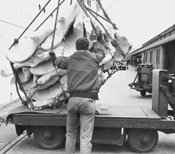
Products are delivered by shippers or suppliers to a receiving dock, where they are then entered into either a manual or computerized inventory system, assigned a storage rack or “slot” location (an address) and then transported to that location, usually by mechanical means (conveyors, AS/RS, fork-lift trucks or tractors). Once a customer order is received, the desired containers or cases must be retrieved from their slot location. Where full pallets are retrieved, mechanical means (a fork-lift or tractor operator) are used (see figure 1). When less than a full pallet load (one or more cases from a rack or slot) is to be retrieved, manual material handling is required, using a worker called a selector, who will choose the desired number of cases and place them either onto a mechanical pallet mover, a push cart or a conveyor. The individual customer order is assembled onto a pallet or similar container for shipment to the customer; a label, tag or other mark containing invoice/billing and/or routing instructions is then applied. This task may be performed by the order selector or fork-lift operator, or, where conveyors are used to deliver single cases for final assembly, by an assembler. When the order is ready for shipment, it is loaded by mechanical means onto the truck, trailer, railroad car or ship. (See figure 2).
Figure 1. A fork-lift truck in a warehouse in the United Kingdom being loaded with apples.
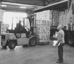
Figure 2. A dockworker in the United Kingdom using lifting machines to move quarters of beef.
Approximately 60% of the work activity in the warehouse is directly related to travel; the remainder relates to manual material handling. Aside from the important work of clerks, dispatchers, cleaners, supervisors and managers, the main work of the warehouse relating to the transporting and handling of goods is performed primarily by two classes of workers: fork-lift operators and selectors.
Intense worldwide competition and the rapid entrance of new firms have created the drive for increased labour and space efficiency, spawning a new discipline called warehouse management systems (WMSs) (Register 1994). These systems are becoming increasingly less expensive and more powerful; they rely on computer networks, bar coding, computer software and radio-frequency communications systems to vastly increase management and control of warehouse inventory and operations, allowing warehouses to improve customer order response times and responsiveness while dramatically increasing inventory accuracy and reducing costs (Firth 1995).
WMSs essentially computerize inventory and order dispatch systems. When incoming product from a supplier or shipper arrives at the receiving dock, bar code scanners record the product code and name, instantly updating the inventory database while assigning the incoming product an address in the warehouse. A fork-lift operator is then alerted to pick up and deliver the stock via a radio-frequency communications system mounted on the vehicle.
Orders from customers are received by another computer program which looks up the product address and availability of each item ordered in the inventory database and then sorts the customer order by the most efficient travel path to minimize travel. Labels with the product name, code and location are printed out for use by the order selectors who must then fill this order. While these features clearly help improve customer service and improve efficiency, they are important preconditions for engineered work standards (EWSs), which may pose additional health and safety hazards for both fork-lift operators and order selectors.
Information about each order—the number of cases, travel distances and so on—which is generated by the order dispatch programme can be further combined with standard or allowed times for each activity to calculate an overall standard time for selecting a particular customer order; it would be extremely time-consuming and difficult to retrieve this information without the use of the computer hardware and databases. Computer monitoring can then be used to record the elapsed time on each order, compare the actual with the allowed time and then compute an efficiency index, which any supervisor or manager can look up by pressing a few computer keys.
Warehouse EWSs have spread from the United States to Australia, Canada, the United Kingdom, Germany, Austria, Finland, Sweden, Italy, South Africa, the Netherlands and Belgium. While WMS systems themselves do not necessarily add safety and health hazards, there is considerable evidence to suggest that the resulting increased workload, lack of control over work pace and the impact of increased frequency of lifting contribute significantly to increased injury risk. In addition, the time pressure imposed by work standards may force workers to take risky short cuts and not utilize proper safe work methods. These risks and hazards are described below.
Hazards
In the most basic warehouse, regardless of the level of technology and computerization, there are a myriad of basic health and safety hazards; modern WMSs can be linked with a different order of health and safety hazards.
Basic health hazards begin with potentially toxic materials which may be stored in warehouses; examples include petroleum products, solvents and dyestuffs. These require proper labelling, employee education and training and an effective hazard communication programme (including MSDSs) for all affected workers, who often know little about the health effects of what they are handling, much less proper handling, spill and clean-up procedures. (See, for example, the ILO Chemicals Convention, 1990 (No. 170), and Recommendation, 1990 (No. 177).) Noise may be present from gasoline or LP-powered fork-lifts, conveyors, ventilation systems and pneumatically-actuated equipment. Additionally, workers who operate such equipment may be subject to whole-body vibration. (See, for example, the ILO Working Environment (Air Pollution, Noise and Vibration) Convention, 1977 (No. 148), and Recommendation, 1977 (No. 156).)
Both fork-lift operators and selectors may be exposed to diesel and gasoline exhaust from trucks at the loading and receiving docks, as well as from fork-lifts. Lighting may not be adequate for fork-lift and other vehicle traffic or for ensuring proper identification of products desired by customers. Workers assigned to work in cold and frozen storage areas may experience cold stress from exposure to cold temperatures and air recirculation systems; temperatures in many freezer storage areas can approach –20ºC, even without wind chill factors being considered. Moreover, since few warehouses are air conditioned during warm months, warehouse workers, particularly those performing manual material handling, may be exposed to heat stress problems.
Safety hazards and risks are also many and varied. Besides the more obvious hazards evident when pedestrians and any motor-driven vehicle are put into the same work area, many of the injuries occurring among warehouse workers include slips, trips and falls from floors not kept free of ice, water or spilled product or that are poorly maintained; a number of injuries involve fork-lift operators who slip or fall while mounting or dismounting their fork-lift trucks.
Workers are often exposed to falling product from overhead racks. Workers may be caught in or between fork-lift masts, forks and cargo, resulting in serious physical injury. Wooden pallets handled by workers often result in exposure to slivers and related puncture wounds. Using knives to cut apart boxes and cases often results in cuts and lacerations. Workers who move boxes or containers on or off conveyors may be exposed to in-running nip points. Selectors, assemblers and other workers engaged in manual material handling are exposed to varying degrees of risk of developing low-back pain and other related injuries. Weight-lifting regulations and recommended methods for materials handling are discussed elsewhere in the Encyclopaedia.
Recordable injuries and lost workday cases in the US warehouse industry, for example, are considerably higher than those for all industry.
Data regarding injuries (and particular back injuries) among grocery order selectors, the group at greatest risk from lifting-related injuries, are not available on a national or international scale. The US NIOSH, however, has studied lifting and other related injuries at two grocery warehouses in the United States (see US NIOSH) and found that “all order selectors have an elevated risk for musculoskeletal disorders, including low-back pain, because of the combination of adverse job factors, all contributing to fatigue, a high metabolic load and the workers’ inability to regulate their work rate because of the work requirements” (NIOSH 1995).
A comprehensive application of ergonomics to the warehouse should not be confined to lifting and to order selectors. A wide focus is required, involving detailed job analysis, careful measurement and assessment (part of the job analysis begins with the job safety analyses below). A more comprehensive look at the design of racks and shelves is required, as is establishment of a closer working relationship with suppliers to design or retrofit fork-lift controls to reduce ergonomic risk factors (extensive reaches, foot flexion and extension, winging, awkward neck and body positions) and to design containers that are less heavy and bulky, with handles or grips to reduce lifting risk.
Corrective Actions
Basic health hazards
Employers, workers and trade unions should cooperate to develop and implement an effective hazard communication programme which emphasizes the three following fundamentals:
- adequate labelling of all toxic substances
- availability of detailed MSDSs that provide more detailed information about health effects, fire, reactivity, PPE, first aid, spill clean-up and other emergency procedures
- regular and relevant worker training in proper handling of these substances.
Lack of an effective hazard communication programme is one of the most frequent standards violations cited in this industry by the US Occupational Safety and Health Administration (OSHA).
Noise and vibration from mechanical equipment, conveyors and other sources require frequent noise and vibration testing and worker training, as well as engineering controls where needed. These controls are most effective when applied at the source of the noise in the form of noise insulation, mufflers and other controls (since most fork-lift operators are seated on top of the engine, vibration and noise dampening at this point are generally most effective). Lighting should be checked frequently and maintained at levels sufficient to reduce vehicle-pedestrian accidents and ensure that product identification and other information can be easily read. Heat (or cold) stress prevention programmes should be implemented for workplaces in warm and humid climates and for selectors or fork-lift operators assigned to cold storage or freezer rooms, to ensure that workers receive adequate breaks, fluids, training and information and that other preventive measures are implemented. Finally, where diesel or petroleum-based fuels are used, exhaust systems should be periodically tested for emissions of carbon monoxide and nitrogen oxides to ensure that they are within safe levels. Proper maintenance of vehicles and restricting their use to adequately ventilated areas will also help reduce the risk of over-exposure to these emissions.
Safety hazards for fork-lift and vehicle operators
Vehicle-pedestrian accidents are a constant risk in any warehouse. Pedestrian lanes should be clearly marked and respected. All vehicle operators should receive training in the safe operation of the vehicle, including traffic rules and speed limits; refresher training should also be considered. Mirrors should be installed at busy intersections or at blind corners to enable vehicle operators to check for traffic or pedestrians before proceeding, and operators should sound their horn before proceeding; back-up beepers or signals may also be considered. Dockplates from loading and receiving docks to the truck, railroad car or barge need to be sufficient to support the load and adequately secured.
Table 2 gives a job safety analysis for fork-lift operators, with recommendations.
Table 2. Job safety analysis: Fork-lift operator.
|
Job elements or tasks |
Hazards present |
Recommended protective actions |
|
Mounting/dismounting fork-lift |
Slipping/tripping on floor (grease, water, cardboard) during mounting/dismounting; back or shoulder strain from repeated incorrect entry/exit and bumping head on protective structure |
Proper maintenance and clean-up of floors, particularly in high-traffic areas; exercising caution when mounting/dismounting; using three-point method to get in and out of fork-lift cab, being careful not to bump your head on overhead protective structure: grasping the support beams for the overhead protective structure with both hands, placing the left foot into the foot-hold (if one is provided) and then pushing off with the right foot and levering oneself into the cab. |
|
Driving with and without loads |
Pedestrian traffic and other vehicles might cross path suddenly; inadequate lighting; noise and vibration hazards; turning and twisting neck into awkward postures; steering may require wrist deviation, winging and/or excessive force; brake and accelerator pedals often require awkward foot and leg posture together with static loading |
Slowing down in high traffic areas; waiting and sounding horn at all crossings with other aisles; exercising caution around other pedestrians; observing speed limits; ensuring proper lighting is provided and maintained through periodic inspections of illumination; installing and maintaining material that dampens noise and vibration on all vehicles and equipment; regular noise testing; operators should twist their upper torso at their waist, not at their neck, particularly when looking behind mirrors installed on the fork-lift and throughout the work facility will also help reduce this risk factor; purchasing, retrofiting and maintaining power steering and steering wheels which can tilt and raise to fit operators and avoiding winging; providing frequent rest breaks for recovery from static loading fatigue; considering redesign of foot pedals to reduce angle of foot (extension) and by hinging accelerator pedals to the floor |
|
Raising or lowering forks with or without loads |
Leaning and twisting of neck in order to see load clearly; reaching for hand controls which may involve excess reach or winging |
Twisting or leaning from the waist, not from the neck; selecting fork-lifts which provide adequate visibility about the mast and which have hand controls within easy reach (located at side of operator, not on control console by steering wheel), but which are not so close or high as to involve winging; possibly retrofiting fork-lifts, with manufacturer’s permission. |
|
Filling gas tanks or changing batteries |
Changing LPG or gasoline tanks or batteries may require excessive and awkward lifting |
Using at least two employees to lift, or using a mechanical hoist; considering redesign of fork-lift to facilitate a more accessible location for fuel tank |
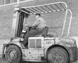
Implementing ergonomic solutions will require closer coordination with fork-lift and vehicle manufacturers; relying solely upon operator training and traffic rules will not eliminate hazards by itself. In addition, safety and health regulatory agencies have prepared mandatory standards for the design and use of fork-lifts—for example, requiring overhead guards to offer protection against falling objects (see figure 3).
Figure 3. An overhead guard fitted to a fork-lift truck.
Safety hazards for order selectors
Table 3 is a job safety analysis listing most of the corrective actions necessary to reduce the safety and lifting hazards for order selectors. However, just as improved fork-lift design to reduce ergonomic risk factors requires closer coordination with vehicle manufacturers, reducing safety and lifting hazards for order selectors requires similar coordination with designers of racking systems, consultants who design and install warehouse control systems and engineered standards systems and the vendors who store their products in the warehouse. The latter can be enlisted to design products that are less bulky, weigh less and have better handles or grips. Rack manufacturers can be very helpful in designing and retrofitting rack systems which allow the selector to stand upright during selection.
Table 3. Job safety analysis: Order selector.
|
Job elements or tasks |
Hazards present |
Recommended protective actions |
|
Mounting/dismounting pallet jack |
Slipping/tripping on floor (grease, water, cardboard) during mounting/dismounting |
Proper maintenance and clean-up of floors, particularly in high-traffic areas; exercising caution when mounting/dismounting |
|
Travel up and down aisles |
Pedestrian traffic and other vehicles might cross path suddenly; lighting; noise |
Slowing down in high-traffic areas; waiting and sounding horn at all crossings with other aisles; exercising caution around other pedestrians; observing speed limits; ensuring that proper lighting is provided and maintained; installing and maintaining material that dampens noise and vibration on all vehicles and equipment; regular noise testing |
|
Select case from rack, walk to pallet, place case on pallet |
Lifting injuries, shoulder, back and neck strain; bumping head on racks; heat stress; cold stress in freezer or cold rooms |
Working in conjunction with vendors to reduce container weight to lowest possible levels and to install handles or better grips on bulky or heavy products; storing heavy products at knuckle height or higher; not storing products to require significant lifting over the shoulder, or provide steps, stairs or platforms; providing “turntable” pallets which can be rotated when selecting products, to avoid stretching; modifying carts or pallet jacks to raise higher, to minimize bending and stooping when placing product on the cart or pallet jack; restricting the “cube” of the pallet so that over-the-shoulder lifting is minimized; providing regular heat and cold stress monitoring; providing adequate fluids, conditioning programmes, clothing and frequent rest breaks |
|
Separate pallets to wrap, mark or drop off at loading docks |
Slipping/tripping on floor (grease, water, cardboard) during mounting/dismounting |
Proper maintenance and clean-up of floors, particularly in high traffic areas; exercising caution when mounting/dismounting |
Consultants who design and install warehouse control systems and engineered standards need to be more aware of the health and safety risks concerning the effect of work intensification on manual material-handling injuries. NIOSH (1993a, 1995) has recommended that more objective forms of determining fatigue allowance, such as oxygen consumption or heart rate, be used. They have also recommended that the height of the pallet being constructed (the “cube”) be limited to no more than 150 cm, and that there be an “order break” after one pallet has been assembled by the order selector, thus increasing the frequency of recovery periods between orders. In addition to more frequent breaks, NIOSH has recommended restricting overtime for workers based on engineered standards, considering worker rotation and installing “light duty” programmes for order selectors who return from injury or leave.
Storage and Transportation of Crude Oil, Natural Gases, Liquid Petroleum Products and Other Chemicals
Pipelines, marine vessels, tank trucks, rail tank cars and so forth are used to transport crude oils, compressed and liquefied hydrocarbon gases, liquid petroleum products and other chemicals from their point of origin to pipeline terminals, refineries, distributors and consumers.
Crude oils and liquid petroleum products are transported, handled and stored in their natural liquid state. Hydrocarbon gases are transported, handled and stored in both the gaseous and liquid states and must be completely confined in pipelines, tanks, cylinders or other containers prior to use. The most important characteristic of liquefied hydrocarbon gases (LHGs) is that they are stored, handled and shipped as liquids, taking up a relatively small amount of space and then expanding into a gas when used. For example, liquefied natural gas (LNG) is stored at –162°C, and when it is released the difference in storage and atmospheric temperatures causes the liquid to expand and gasify. One gallon (3.8 l) of LNG converts to approximately 2.5 m3 of natural gas at normal temperature and pressure. Because liquefied gas is much more “concentrated” than compressed gas, more useable gas can be transported and provided in the same size container.
Pipelines
It is generally the case that all crude oils, natural gas, liquefied natural gas, liquefied petroleum gas (LPG) and petroleum products flow through pipelines at some time in their migration from the well to a refinery or gas plant, then to a terminal and eventually to the consumer. Aboveground, underwater and underground pipelines, varying in size from several centimetres to a metre or more in diameter, move vast amounts of crude oil, natural gas, LHGs and liquid petroleum products. Pipelines run throughout the world, from the frozen tundra of Alaska and Siberia to the hot deserts of the Middle East, across rivers, lakes, seas, swamps and forests, over and through mountains and under cities and towns. Although the initial construction of pipelines is difficult and expensive, once they are built, properly maintained and operated, they provide one of the safest and most economical means of transporting these products.
The first successful crude-oil pipeline, a 5-cm-diameter wrought iron pipe 9 km long with a capacity of about 800 barrels a day, was opened in Pennsylvania (US) in 1865. Today, crude oil, compressed natural gas and liquid petroleum products are moved long distances through pipelines at speeds from 5.5 to 9 km per hour by large pumps or compressors located along the route of the pipeline at intervals ranging from 90 km to over 270 km. The distance between pumping or compressor stations is determined by the pump capacity, viscosity of the product, size of the pipeline and the type of terrain crossed. Regardless of these factors, pipeline pumping pressures and flow rates are controlled throughout the system to maintain a constant movement of product within the pipeline.
Types of pipelines
The four basic types of pipelines in the oil and gas industry are flow lines, gathering lines, crude trunk pipelines and petroleum product trunk pipelines.
- Flow lines. Flow lines move crude oil or natural gas from producing wells to producing field storage tanks and reservoirs. Flow lines may vary in size from 5 cm in diameter in older, lower-pressure fields with only a few wells, to much larger lines in multi-well, high-pressure fields. Offshore platforms use flow lines to move crude and gas from wells to the platform storage and loading facility. A lease line is a type of flow line which carries all of the oil produced on a single lease to a storage tank.
- Gathering and feeder lines. Gathering lines collect oil and gas from several locations for delivery to central accumulating points, such as from field crude oil tanks and gas plants to marine docks. Feeder lines collect oil and gas from several locations for delivery direct into trunk lines, such as moving crude oil from offshore platforms to onshore crude trunk pipelines. Gathering lines and feeder lines are typically larger in diameter than flow lines.
- Crude trunk pipelines. Natural gas and crude oil are moved long distances from producing areas or marine docks to refineries and from refineries to storage and distribution facilities by 1- to 3-m- or larger-diameter trunk pipelines.
- Petroleum product trunk pipelines. These pipelines move liquid petroleum products such as gasoline and fuel oil from refineries to terminals, and from marine and pipeline terminals to distribution terminals. Product pipelines may also distribute products from terminals to bulk plants and consumer storage facilities, and occasionally from refineries direct to consumers. Product pipelines are used to move LPG from refineries to distributor storage facilities or large industrial users.
Regulations and standards
Pipelines are constructed and operated to meet safety and environmental standards established by regulatory agencies and industry associations. Within the United States, the Department of Transportation (DOT) regulates the operation of pipelines, the Environmental Protection Agency (EPA) regulates spills and releases, the Occupational Safety and Health Administration (OSHA) promulgates standards covering worker health and safety, and the Interstate Commerce Commission (ICC) regulates common carrier pipelines. A number of industry organizations, such as the American Petroleum Institute and the American Gas Association, also publish recommended practices covering pipeline operations.
Pipeline construction
Pipeline routes are planned using topographic maps developed from aerial photogrammetric surveys, followed by actual ground surveying. After planning the route, obtaining right-of-way and permission to proceed, base camps are established and a means of access for construction equipment is required. Pipelines can be constructed working from one end to another or simultaneously in sections which are then connected.
The first step in laying pipeline is to construct a 15- to 30-m-wide service road along the planned route to provide a stable base for the pipe-laying and pipe-joining equipment and for underground pipeline excavation and backfill equipment. The pipe sections are laid on the ground alongside the service road. The ends of the pipe are cleaned, the pipe is bent horizontally or vertically, as necessary, and the sections are held in position by chocks above the ground and joined by multi-pass electrical arc-welding. The welds are checked visually and then with gamma radiation to assure that no defects are present. Each connected section is then coated with liquid soap and air-pressure tested to detect leaks.
The pipeline is cleaned, primed and coated with a hot, tar-like material to prevent corrosion and wrapped in an outer layer of heavy paper, mineral wool or plastic. If the pipe is to be buried, the bottom of the trench is prepared with a sand or gravel bed. The pipe may be weighed down by short, concrete sleeves to prevent its lifting out of the trench from groundwater pressure. After the underground pipeline is placed in the trench, the trench is backfilled and the surface of the ground returned to normal appearance. After coating and wrapping, aboveground piping is lifted up onto prepared stanchions or casements, which may have various design features such as anti-earthquake shock absorption. Pipelines may be insulated or have heat trace capabilities to keep products at desired temperatures throughout transport. All pipeline sections are hydrostatically tested prior to entering gas or liquid hydrocarbon service.
Pipeline operations
Pipelines may be either privately owned and operated, carrying only the owner’s products, or they may be common carriers, required to carry any company’s products provided that the pipeline’s product requirements and tariffs are met. The three major pipeline operations are pipeline control, pumping or compressor stations and delivery terminals. Storage, cleaning, communication and shipment are also important functions.
- Pipeline control. Regardless of the product being transported, the size and length of the pipeline or the terrain, pipeline pumping stations, pressures and flow rates are completely controlled in order to ensure appropriate flow rates and continuous operations. Typically an operator and computer control the pumps, valves, regulators and compressors throughout the pipeline system from a central location.
- Oil pumping and gas compressor stations. Crude oil and petroleum products pumping stations and gas compressor stations are located at wellheads and along the pipeline route as needed to maintain pressure and volume. Pumps are driven by electric motors or diesel engines, and turbines may be powered by fuel oil, gas or steam. Many of these stations are automatically controlled and not staffed at most times. Pumps, with and without vapour return lines or pressure equalizing lines, are commonly used in smaller pipelines for transport of LNG, LPG and compressed natural gas (CNG). Pressure drop detectors are installed to signal any leaks in pipelines, and excess flow valves or other flow limiting devices are used to minimize the rate of flow in case of a pipeline leak. Storage vessels and reservoirs may be isolated from main pipelines by manually operated or remote control valves or fusible link valves.
- Pipeline product storage. Crude and petroleum product pipeline terminals have breakout storage tanks to which shipments may be diverted, where they are held until required by a refinery, terminal or user (see figure 1). Other tanks at pipeline pumping stations contain fuel for operating diesel-driven pump motors or for running electrical generators. Because gas fields produce continuously and gas pipelines operate continuously, during times of reduced demand, such as summertime, liquefied natural and petroleum gases are stored underground in natural caverns or salt domes until needed.
- Pipeline cleaning. Pipelines are cleaned on a scheduled basis or as necessary in order to continue flow by reducing friction and maintaining as large a diameter interior as possible. A special cleaning device, called a pig or go-devil, is placed into the pipeline and pushed along by the flow of oil from one pumping station to the next. As the pig passes through the pipeline it scrapes off any dirt, wax or other deposits which have built up inside the pipeline walls. When it reaches a pumping station, the pig is removed, cleaned and reinserted into the pipeline to travel to the next station.
- Communications. It is important that there be communication and agreement concerning schedules, pumping rates and pressures and emergency procedures between pipeline stations and operators and those shipping and receiving crude oil, gas and petroleum products. Some pipeline companies have private telephone systems which transmit the signal along the pipeline, while others use radios or public telephones. Many pipelines use ultra-high-frequency microwave transmitter systems for computer communications between control centres and pumping stations.
- Petroleum product shipment. Petroleum products may be shipped a number of different ways on pipelines. A company operating a refinery may blend a specific grade of its own gasoline with appropriate additives (additize) and ship a batch through a pipeline directly to its own terminal for distribution to its customers. Another method is for a refinery to produce a batch of gasoline, called a frangible or specification product, which is blended to meet a common carrier pipeline company’s product specifications. The gasoline is placed into the pipeline for delivery to any company’s terminals which are connected to the pipeline system. In a third method, products are shipped by companies to each other’s terminals and exchanged in order to avoid extra transportation and handling. Frangible and exchange products are usually blended and additized at the terminal which receives the product from the pipeline, to meet the specific requirements of each company operating from the terminal. Finally, some products are delivered by pipeline from terminals and refineries direct to large commercial consumers—jet fuel to airports, gas to gas distribution companies and fuel oil to electric generating plants.
- Product receipt and delivery. Pipeline operators and terminal operators should jointly establish programmes to provide for the safe receipt and transfer of products and to coordinate actions in case an emergency occurs on the pipeline or at the terminal during shipment which requires shutdown or diversion of product.
Figure 1. A terminal operator transfers product the Pasagoula Refinery into holding tanks in the Deraville Terminal near Atlanta, Georgia, US.
American Petroleum Institute
Instructions for receiving pipeline deliveries should include verification of the availability of the storage tanks to hold the shipment, opening and aligning tank and terminal valves in anticipation of delivery, checking to assure that the proper tank is receiving product immediately after the start of delivery, conducting required sampling and testing of batches at the start of delivery, performing batch changes and tank switches as required, monitoring receipts to assure that overfills do not occur and maintaining communications between the pipeline and the terminal. The use of written communications between terminal workers, especially when shift changes occur during product transfer, should be considered.
Batch shipments and interface
Although pipelines originally were used to move only crude oil, they evolved into carrying all types and different grades of liquid petroleum products. Because petroleum products are transported in pipelines by batches, in succession, there is commingling or mixing of the products at the interfaces. The product intermix is controlled by one of three methods: downgrading (derating), using liquid and solid spacers for separation or reprocessing the intermix. Radioactive tracers, colour dyes and spacers may be placed into the pipeline to identify where the interfaces occur. Radioactive sensors, visual observation or gravity tests are conducted at the receiving facility to identify different pipeline batches.
Petroleum products are normally transported through pipelines in batch sequences with compatible crude oils or products adjoining one another. One method of maintaining product quality and integrity, downgrading or derating, is accomplished by lowering the interface between the two batches to the level of the least affected product. For example, a batch of high-octane premium gasoline is typically shipped immediately before or after a batch of lower-octane regular gasoline. The small quantity of the two products which has intermixed will be downgraded to the lower octane rating regular gasoline. When shipping gasoline before or after diesel fuel, a small amount of diesel interface is allowed to blend into the gasoline, rather than blending gasoline into the diesel fuel, which could lower its flashpoint. Batch interfaces are typically detected by visual observation, gravitometers or sampling.
Liquid and solid spacers or cleaning pigs may be used to physically separate and identify different batches of products. The solid spacers are detected by a radioactive signal and diverted from the pipeline into a special receiver at the terminal when the batch changes from one product to another. Liquid separators may be water or another product that does not commingle with either of the batches it is separating and is later removed and reprocessed. Kerosene, which is downgraded (derated) to another product in storage or is recycled, can also be used to separate batches.
A third method of controlling the interface, often used at the refinery ends of pipelines, is to return the interface to be reprocessed. Products and interfaces which have been contaminated with water may also be returned for reprocessing.
Environmental protection
Because of the large volumes of products which are transported by pipelines on a continuous basis, there is opportunity for environmental damage from releases. Depending on company and regulatory safety requirements and the pipeline’s construction, location, weather, accessibility and operation, a considerable amount of product may be released should a break in the line or leak occur. Pipeline operators should have emergency response and spill contingency plans prepared and have containment and clean-up materials, personnel and equipment available or on call. Simple field solutions such as building earth dykes and drainage ditches can be quickly implemented by trained operators to contain and divert spilled product.
Maintaining pipelines and worker health and safety
The first pipelines were made of cast iron. Modern trunk pipelines are constructed of welded, high-strength steel, which can withstand high pressures. Pipe walls are periodically tested for thickness to determine whether internal corrosion or deposits have occurred. Welds are checked visually and with gamma radiation to assure that no defects are present.
Plastic pipe may be used for low-pressure, small-diameter flow lines and gathering lines in gas and crude-oil-producing fields, since plastic is light in weight and easy to handle, assemble and move.
When a pipeline is separated by cutting, spreading flanges, removing a valve or opening the line, an electrostatic arc may be created by impressed cathodic protection voltage, corrosion, sacrificial anodes, nearby high-voltage power lines or stray ground currents. This should be minimized by grounding (earthing) the pipe, de-energizing the cathodic rectifiers closest to both sides of the separation and connecting a bonding cable to each side of the piping prior to starting work. As additional pipeline sections, valves and so on are added to an existing line, or during construction, they should first be bonded to the pipelines in place.
Work on pipelines should cease during electrical storms. Equipment used to lift and place pipe should not be operated within 3 m of high-voltage electric lines. Any vehicles or equipment working in the vicinity of high-voltage lines should have trailing grounding straps attached to the frames. Temporary metal buildings should also be grounded.
Pipelines are specially coated and wrapped to prevent corrosion. Cathodic electrical protection may also be required. After the pipeline sections are coated and insulated, they are joined by special clamps connected to metallic anodes. The pipeline is subjected to a grounded source of direct current of sufficient capacity so that the pipeline acts as a cathode and does not corrode.
All pipeline sections are hydrostatically tested prior to entering gas or liquid hydrocarbon service and, depending on regulatory and company requirements, at regular intervals during the life of the pipeline. Air must be eliminated from pipelines prior to hydrostatic testing, and hydrostatic pressure built up and reduced at safe rates. Pipelines are regularly patrolled, usually by aerial surveillance, to visually detect leaks, or monitored from the control centre to detect a drop in flow rate or pressure, which would signify that a break in the pipeline has occurred.
Pipeline systems are provided with warning and signalling systems to alert operators so they may take corrective action in an emergency. Pipelines may have automatic shutdown systems which activate emergency pressure valves upon sensing increased or reduced pipeline pressure. Manually or automatically operated isolation valves are typically located at strategic intervals along pipelines, such as at pumping stations and at both sides of river crossings.
An important consideration when operating pipelines is to provide a means of warning contractors and others who may be working or conducting excavations along the pipeline route, so that the pipeline is not inadvertently ruptured, breached or punctured, resulting in a vapour or gas explosion and fire. This is usually done by regulations which require construction permits or by pipeline companies and associations providing a central number which contractors can call prior to excavation.
Because crude oil and flammable petroleum products are transported in pipelines, the possibility exists for fire or explosion in case of a line break or release of vapour or liquid. Pressure should be reduced to a safe level before working on high-pressure pipelines. Combustible gas testing should be conducted and a permit issued prior to repair or maintenance involving hot work or hot tapping on pipelines. The pipeline should be cleared of flammable liquids and vapours or gas prior to starting work. If a pipeline cannot be cleared and an approved plug is used, safe work procedures should be established and followed by qualified workers. The line should be vented a safe distance from the hot work area to relieve any build-up of pressure behind the plug.
Proper safety procedures should be established and followed by qualified workers when hot tapping pipelines. If welding or hot tapping is conducted in an area where a spill or leak has occurred, the outside of the pipe should be cleaned of liquid, and contaminated soil should be removed or covered to prevent ignition.
It is very important to notify operators at the nearest pumping stations on each side of the operating pipeline where maintenance or repair is to be performed, in case shutdown is required. When crude oil or gas is being pumped into pipelines by producers, the pipeline operators must provide specific instructions to the producers as to actions to take during repair, maintenance or in an emergency. For example, prior to tie-in of production tanks and lines to pipelines, all gate valves and bleeders for the tanks and lines involved in the tie-in should be closed and locked or sealed until the operation is completed.
Normal safety precautions concerning pipe and materials handling, toxic and hazardous exposures, welding and excavation apply during pipeline construction. Workers clearing right-of-way should protect themselves from climatic conditions; poisonous plants, insects and snakes; falling trees and rocks; and so on. Excavations and trenches should be sloped or shored to prevent collapse during underground pipeline construction or repair (see the article “Trenching” in the chapter Construction). Workers should follow safe work practices when opening and de-energizing electrical transformers and switches.
Pipeline operating and maintenance personnel often work alone and are responsible for long stretches of pipeline. Atmospheric testing and the use of personal and respiratory protective equipment is needed to determine oxygen and flammable vapour levels and protect against toxic exposures to hydrogen sulphide and benzene when gauging tanks, opening lines, cleaning spills, sampling and testing, shipping, receiving and performing other pipeline activities. Workers should wear dosimeters or film badges and avoid exposure when working with density gauges, source holders or other radioactive materials. The use of personal and respiratory protective equipment should be considered for exposure to burns from the hot protective tar used in pipe-coating operations and from toxic vapours which contain polynuclear aromatic hydrocarbons.
Marine Tankers and Barges
The majority of the world’s crude oil is transported by tankers from producing areas such as the Middle East and Africa to refineries in consumer areas such as Europe, Japan and the United States. Oil products were originally transported in large barrels on cargo ships. The first tanker ship, which was built in 1886, carried about 2,300 SDWT (2,240 pounds per ton) of oil. Today’s supertankers can be over 300 m long and carry almost 200 times as much oil (see figure 2). Gathering and feeder pipelines often end at marine terminals or offshore platform loading facilities, where the crude oil is loaded into tankers or barges for transport to crude trunk pipelines or refineries. Petroleum products also are transported from refineries to distribution terminals by tanker and barge. After delivering their cargoes, the vessels return in ballast to loading facilities to repeat the sequence.
Figure 2. SS Paul L. Fahrney oil tanker.
American Petroleum Institute
Liquefied natural gas is shipped as a cryogenic gas in specialized marine vessels with heavily insulated compartments or reservoirs (see figure 3). At the delivery port, the LNG is off-loaded to storage facilities or regasification plants. Liquefied petroleum gas may be shipped both as a liquid in uninsulated marine vessels and barges and as a cryogenic in insulated marine vessels. Additionally, LPG in containers (bottled gas) may be shipped as cargo on marine vessels and barges.
Figure 3. LNG Leo tanker loading at Arun, Sumatra, Indonesia.
American Petroleum Institute
LPG and LNG marine vessels
The three types of marine vessels used for transport of LPG and LNG are:
- vessels with reservoirs pressurized up to 2 mPa (LPG only)
- vessels with heat-insulated reservoirs and a reduced pressure of 0.3 to 0.6 mPa (LPG only)
- cryogenic vessels with heat-insulated reservoirs pressurized close to atmospheric pressure (LPG and LNG).
Shipment of LHGs on marine vessels requires constant safety awareness. Transfer hoses must be suitable for the correct temperatures and pressures of the LHGs being handled. To prevent a flammable mixture of gas vapour and air, inert gas (nitrogen) blanketing is provided around reservoirs, and the area is continually monitored to detect leaks. Before loading, storage reservoirs should be inspected to ensure that they are free of contaminants. If reservoirs contain inert gas or air, they should be purged with LHG vapour prior to loading the LHG. Reservoirs should be constantly inspected to ensure integrity, and safety valves should be installed to relieve the LHG vapour generated at maximum heat load. Marine vessels are provided with fire suppression systems and have comprehensive emergency response procedures in place.
Crude oil and petroleum products marine vessels
Oil tankers and barges are vessels designed with the engines and quarters at the rear of the vessel and the remainder of the vessel divided into special compartments (tanks) to carry crude oil and liquid petroleum products in bulk. Cargo pumps are located in pump rooms, and forced ventilation and inerting systems are provided to reduce the risk of fires and explosions in pump rooms and cargo compartments. Modern oil tankers and barges are built with double hulls and other protective and safety features required by the United States Oil Pollution Act of 1990 and the International Maritime Organization (IMO) tanker safety standards. Some new ship designs extend double hulls up the sides of the tankers to provide additional protection. Generally, large tankers carry crude oil and small tankers and barges carry petroleum products.
- Supertankers. Ultra-large and very large crude carriers (ULCCs and VLCCs) are restricted by their size and draft to specific routes of travel. ULCCs are vessels whose capacity is over 300,000 SDWTs, and VLCCs have capacities ranging from 160,000 to 300,000 SDWTs. Most large crude carriers are not owned by oil companies, but are chartered from transportation companies which specialize in operating these super-sized vessels.
- Oil tankers. Oil tankers are smaller than VLCCs, and, in addition to ocean travel, they can navigate restricted passages such as the Suez and Panama Canals, shallow coastal waters and estuaries. Large oil tankers, which range from 25,000 to 160,000 SDWTs, usually carry crude oil or heavy residual products. Smaller oil tankers, under 25,000 SDWT, usually carry gasoline, fuel oils and lubricants.
- Barges. Barges operate mainly in coastal and inland waterways and rivers, alone or in groups of two or more, and are either self-propelled or moved by tugboat. They may carry crude oil to refineries, but more often are used as an inexpensive means of transporting petroleum products from refineries to distribution terminals. Barges are also used to off-load cargo from tankers offshore whose draft or size does not allow them to come to the dock.
Barge and ship loading and unloading
Vessel-to-shore procedures, safety checklists and guidelines should be established and agreed upon by terminal and marine vessel operators. The International Safety Guide for Oil Tankers and Terminals (International Chamber of Shipping 1978) contains information and samples of checklists, guidelines, permits and other procedures covering safe operations when loading or unloading vessels, which may be used by vessel and terminal operators.
Although marine vessels sit in water and are thereby intrinsically grounded, there is a need to provide protection from static electricity which can build up during loading or unloading. This is accomplished by bonding or connecting metal objects on the dock or loading/unloading apparatus to the metal of the vessel. Bonding is also accomplished by use of conductive loading hose or piping. An electrostatic spark of ignitable intensity may also be generated when lowering equipment, thermometers or gauging devices into compartments immediately after loading; enough time must be allowed for the static charge to dissipate.
Ship-to-shore electric currents, which are different from static electricity, may be generated by cathodic protection of the vessel’s hull or dock, or by galvanic potential differences between the vessel and the shore. These currents also build up in metal loading/unloading apparatus. Insulating flanges may be installed within the length of the loading arm and at the point where flexible hoses connect to the shore pipeline system. When the connections are broken, there is no opportunity for a spark to jump from one metal surface to another.
All vessels and terminals need mutually agreed upon emergency response procedures in case of a fire or release of product, vapour or toxic gas. These must cover emergency operations, stopping product flow and emergency removal of a vessel from the dock. The plans should consider communications, fire-fighting, vapour cloud mitigation, mutual aid, rescue, clean-up and remediation measures.
Fire protection portable equipment and fixed systems should be in accord with government and company requirements and appropriate to the size, function, exposure potential and value of the dock and wharf facilities. The International Safety Guide for Oil Tankers and Terminals (International Chamber of Shipping 1978) contains a sample fire notice which may be used as a guide by terminals for dock fire prevention.
Marine vessel health and safety
In addition to the usual maritime working hazards, transporting crude oil and flammable liquids by marine vessel creates a number of special health, safety and fire prevention situations. These include surging and expansion of liquid cargo, flammable vapour hazards during transport and when loading and unloading, possibility of pyrophoric ignition, toxic exposures to materials such as hydrogen sulphide and benzene and safety considerations when venting, flushing and cleaning compart-ments. The economics of operating modern tankers requires them to be at sea for extended periods of time with only short intervals in port to load or unload cargo. This, together with the fact that tankers are highly automated, creates unique mental and physical demands on the few crew members used to operate the vessels.
Fire and explosion protection
Emergency plans and procedures should be developed and implemented that are appropriate for the type of cargo on board and other potential hazards. Fire-fighting equipment must be supplied. Response team members who have shipboard fire-fighting, rescue and spill clean-up responsibilities should be trained, drilled and equipped to handle potential emergencies. Water, foam, dry chemicals, halon, carbon dioxide and steam are used as cooling, inhibiting and smothering fire-fighting agents aboard marine vessels, although halon is being phased out due to environmental concerns. The requirements for vessel fire-fighting equipment and systems are established by the country under whose flag the vessel sails and by company policy, but usually follow the recommendations of the 1974 International Convention for the Safety of Life at Sea (SOLAS).
Strict control of flames or naked lights, lighted smoking materials and other sources of ignition, such as welding or grinding sparks, electrical equipment and unprotected light bulbs, is required on vessels at all times to reduce the risk of fire and explosion. Prior to conducting hot work on board marine vessels, the area should be examined and tested to assure that conditions are safe, and permits should be issued for each specific task allowed.
One method of preventing explosions and fires in the vapour space of cargo compartments is to maintain the level of oxygen below 11% by making the atmosphere inert with a noncombustible gas. Sources for inert gas are exhaust gases from the vessel’s boilers or an independent gas generator or a gas turbine fitted with an afterburner. The 1974 SOLAS Convention implies that vessels carrying cargo with flashpoints below 60°C should have compartments fitted with inert systems. Vessels using inert gas systems should maintain cargo compartments in non-flammable conditions at all times. Inert gas compartments should be constantly monitored to assure safe conditions and should not be allowed to become flammable, because of the danger of ignition from pyrophoric deposits.
Confined spaces
Confined spaces on marine vessels, such as cargo compartments, paint lockers, pump rooms, fuel tanks and spaces between double hulls, must be treated the same as any confined space for entry, hot work and cold work. Tests for oxygen content, flammable vapours and toxic substances, in that order, must be conducted prior to entering confined spaces. A permit system should be established and followed for all confined space entry, safe (cold) work and hot work, which indicates safe exposure levels and required personal and respiratory protective equipment. In waters of the United States, these tests may be conducted by qualified individuals called “marine chemists”.
Compartments on marine vessels such as cargo tanks and pump rooms are confined spaces; when cleaning those which have been made inert or have flammable vapour, toxic or unknown atmospheres, they should be tested, and special safety and respiratory protection procedures should be followed. After crude oil has been unloaded, a small amount of residue, called clingage, remains on the interior surfaces of the compartments, which may then be washed and filled with water for ballast. One method of reducing the amount of residue is to install fixed equipment which removes up to 80% of the clingage by washing down the sides of inerted compartments with crude oil during unloading.
Pumps, valves and equipment
A work permit should be issued and safe work procedures followed, such as bonding, draining and vapour freeing, flammable vapour and toxic exposure testing, and providing stand-by fire protection equipment when operations, maintenance or repair requires opening cargo pumps, lines, valves or equipment on board marine vessels.
Toxic exposures
There is an opportunity for vented gases such as flue gas or hydrogen sulphide to reach the decks of vessels, even from specially designed vent systems. Testing should be continuously conducted to determine inert gas levels on all vessels and hydrogen sulphide levels on vessels which contain or previously carried sour crude oil or residual fuel. Tests should be conducted for benzene exposure on vessels carrying crude oil and gasoline. Inert gas scrubber effluent water and condensate water is acidic and corrosive; PPE should be used when contact is possible.
Environmental protection
Marine vessels and terminals should establish procedures and provide equipment to protect the environment from spills on water and land, and from releases of vapour to the air. The use of large vapour recovery systems at marine terminals is growing. Care must be taken to comply with air pollution requirements when vessels vent compartments and enclosed spaces. Emergency response procedures should be established, and equipment and trained personnel should be available to respond to spills and releases of crude oil and flammable and combustible liquids. A responsible person should be designated to ensure that notifications are made to both the company and the appropriate authorities should a reportable spill or release occur.
In the past, the oil-contaminated ballast water and tank washings were flushed out of the compartments at sea. In 1973, the International Convention for Prevention of Pollution from Ships established requirements that before the water is discharged at sea, the oily residue must be separated and retained on board for eventual onshore processing. Modern tankers have segregated ballast systems, with different lines, pumps and tanks than those used for cargo (in accordance with international recommen-dations), so that there is no possibility of contamination. Older vessels still carry ballast in cargo tanks, so special procedures, such as pumping oily water into designated onshore tanks and processing facilities, must be followed when discharging ballast in order to prevent pollution.
Motor Vehicle and Railroad Transport of Petroleum Products
Crude oil and petroleum products were initially transported by horse-drawn tank wagons, then by railroad tank cars and finally by motor vehicles. Following receipt at terminals from marine vessels or pipelines, bulk liquid petroleum products are delivered by non-pressure tank trucks or rail tank cars directly to service stations and consumers or to smaller terminals, called bulk plants, for redistribution. LPG, gasoline anti-knock compounds, hydrofluoric acid and many other products, chemicals and additives used in the oil and gas industry are transported in pressure tank cars and tank trucks. Crude oil may also be transported by tank truck from small producing wells to gathering tanks, and by tank truck and railroad tank car from storage tanks to refineries or main pipelines. Packaged petroleum products in bulk bins or drums and pallets and cases of smaller containers are carried by package truck or railroad box car.
Government regulations
Transportation of petroleum products by motor vehicle or railroad tank car is regulated by government agencies throughout most of the world. Agencies such as the US DOT and the Canadian Transport Commission (CTC) have established regulations governing the design, construction, safety devices, testing, preventive maintenance, inspection and operation of tank trucks and tank cars. Regulations governing railroad tank car and tank truck operations typically include tank pressure and pressure relief device testing and certification before being placed into initial service and at regular intervals thereafter. The Association of American Railroads and the National Fire Protection Association (NFPA) are typical of organizations which publish specifications and requirements for the safe operation of tank cars and tank trucks. Most governments have regulations or adhere to United Nations Conventions which require the identification of and information concerning hazardous materials and petroleum products which are shipped in bulk or in containers. Railroad tank cars, tank trucks and package trucks are placarded to identify any hazardous products being transported and to provide emergency response information.
Railroad tank cars
Railroad tank cars are constructed of carbon steel or aluminium and may be pressurized or unpressurized. Modern tank cars can hold up to 171,000 l of compressed gas at pressures up to 600 psi (1.6 to 1.8 mPa). Non-pressure tank cars have evolved from small wooden tank cars of the late 1800s to jumbo tank cars which transport as much as 1.31 million litres of product at pressures up to 100 psi (0.6 mPa). Non-pressure tank cars may be individual units with one or multiple compartments or a string of interconnected tank cars, called a tank train. Tank cars are loaded individually, and entire tank trains can be loaded and unloaded from a single point. Both pressure and non-pressure tank cars may be heated, cooled, insulated and thermally protected against fire, depending on their service and the products transported.
All railroad tank cars have top- or bottom-liquid or vapour valves for loading and unloading and hatch entries for cleaning. They are also equipped with devices intended to prevent the increase of internal pressure when exposed to abnormal con-ditions. These devices include safety relief valves held in place by a spring which can open to relieve pressure and then close; safety vents with rupture discs that burst open to relieve pressure but cannot reclose; or a combination of the two devices. A vacuum relief valve is provided for non-pressure tank cars to prevent vacuum formation when unloading from the bottom. Both pressure and non-pressure tank cars have protective housings on top surrounding the loading connections, sample lines, thermometer wells and gauging devices. Platforms for loaders may or may not be provided on top of cars. Older non-pressure tank cars may have one or more expansion domes. Fittings are provided on the bottom of tank cars for unloading or cleaning. Head shields are provided on the ends of tank cars to prevent puncture of the shell by the coupler of another car during derailments.
LNG is shipped as a cryogenic gas in insulated tank truck and rail pressure tank cars. Pressure tank trucks and rail tank cars for LNG transport have a stainless steel inner reservoir suspended in an outer reservoir of carbon steel. The annular space is a vacuum filled with insulation to maintain low temperatures during shipment. To prevent gas from igniting back to the tanks, they are equipped with two independent, remotely controlled fail-safe emergency shut-off valves on the filling and discharge lines and have gauges on both the inside and outside reservoirs.
LPG is transported on land in specially designed rail tank cars (up to 130 m3 capacity) or tank trucks (up to 40 m3 capacity). Tank trucks and rail tank cars for LPG transport are typically uninsulated steel cylinders with spherical bottoms, equipped with gauges, thermometers, two safety relief valves, a gas level meter and maximum fill indicator and baffles.
Rail tank cars transporting LNG or LPG should not be overloaded, since they may sit on a siding for some period of time and be exposed to high ambient temperatures, which could cause overpressure and venting. Bond wires and grounding cables are provided at rail and tank truck loading racks to help neutralize and dissipate static electricity. They should be connected before operations commence and not disconnected until operations are complete and all valves are closed. Truck and rail loading facilities are typically protected by fire water spray or mist systems and fire extinguishers.
Tank trucks
Petroleum products and crude oil tank trucks are typically constructed of carbon steel, aluminium or a plasticized fibreglass material, and vary in size from 1,900-l tank wagons to jumbo 53,200-l tankers. The capacity of tank trucks is governed by regulatory agencies, and usually is dependent upon highway and bridge capacity limitations and the allowable weight per axle or total amount of product allowed.
There are pressurized and non-pressurized tank trucks, which may be non-insulated or insulated depending on their service and the products transported. Pressurized tank trucks are usually single compartment, and non-pressurized tank trucks may have single or multiple compartments. Regardless of the number of compartments on a tank truck, each compartment must be treated individually, with its own loading, unloading and safety-relief devices. Compartments may be separated by single or double walls. Regulations may require that incompatible products and flammable and combustible liquids carried in different compartments on the same vehicle be separated by double walls. When pressure testing compartments, the space between the walls should also be tested for liquid or vapour.
Tank trucks have either hatches which open for top loading, valves for closed top- or bottom-loading and unloading, or both. All compartments have hatch entries for cleaning and are equipped with safety relief devices to mitigate internal pressure when exposed to abnormal conditions. These devices include safety relief valves held in place by a spring which can open to relieve pressure and then close, hatches on non-pressure tanks which pop open if the relief valves fail and rupture discs on pressurized tank trucks. A vacuum relief valve is provided for each non-pressurized tank truck compartment to prevent vacuum when unloading from the bottom. Non-pressurized tank trucks have railings on top to protect the hatches, relief valves and vapour recovery system in case of a rollover. Tank trucks are usually equipped with breakaway, self-closing devices installed on compartment bottom loading and unloading pipes and fittings to prevent spills in case of damage in a rollover or collision.
Rail tank car and tank truck loading and unloading
While railroad tank cars are almost always loaded and unloaded by workers assigned to these specific duties, tank trucks may be loaded and unloaded by either loaders or drivers. Tank cars and tank trucks are loaded at facilities called loading racks, and may be top loaded through open hatches or closed connections, bottom loaded through closed connections, or a combination of both.
Loading
Workers who load and unload crude oil, LPG, petroleum products, and acids and additives used in the oil and gas industry, should have a basic understanding of the characteristics of the products handled, their hazards and exposures and the operating procedures and work practices needed to perform the job safely. Many government agencies and companies require the use and completion of inspection forms upon receipt and shipment and prior to loading and unloading railroad tank cars and tank trucks. Tank trucks and railroad tank cars may be loaded through open hatches on the top or through fittings and valves at the top or bottom of each tank or compartment. Closed connections are required when pressure loading and where vapour recovery systems are provided. If loading systems do not activate for any reason (such as improper operation of the vapour recovery system or a fault in the grounding or bonding system), by-pass should not be attempted without approval. All hatches should be closed and securely latched during transit.
Workers should follow safe work practices to avoid slips and falls when top loading. If loading controls use pre-set meters, loaders must be careful to load the correct products into the assigned tanks and compartments. All compartment hatches should be shut when bottom loading, and when top loading, only the compartment being loaded should be open. When top loading, splash loading should be avoided by placing the loading tube or hose close to the bottom of the compartment and starting to load slowly until the opening is submerged. During manual top loading operations, loaders should remain in attendance, not tie down the loading shut-off (deadman) control and not overfill the compartment. Loaders should avoid exposures to product and vapour by standing upwind and averting the head when top loading through open hatches and by wearing protective equipment when handling additives, obtaining samples and draining hoses. Loaders should be aware of and follow prescribed response actions in case of a hose or line rupture, spill, release, fire or other emergency.
Unloading and delivery
When unloading tank cars and tank trucks, it is important first to assure that each product is unloaded into the proper designated storage tank and that the tank has sufficient capacity to hold all of the product being delivered. Although valves, fill pipes, lines and fill covers should be colour coded or otherwise marked to identify the product contained, the driver should still be responsible for product quality during delivery. Any misdelivery of product, mixing or contamination should be immediately reported to the recipient and to the company to prevent serious consequences. When drivers or operators are required to additize products or obtain samples from storage tanks following delivery to assure product quality or for any other reason, all safety and health provisions specific to the exposure should be followed. Persons engaged in delivery and unloading operations should remain in the vicinity at all times and know what to do in an emergency, including notification, stopping product flow, cleaning spills and when to leave the area.
Pressurized tanks may be unloaded by compressor or pump, and unpressurized tanks by gravity, vehicle pump or recipient pump. Tank trucks and tank cars which carry lubrication or industrial oils, additives and acids are sometimes unloaded by pressurizing the tank with an inert gas such as nitrogen. Tank cars or tank trucks may need to be heated using steam or electric coils in order to unload heavy crude oils, viscous products and waxes. All of these activities have inherent dangers and exposures. Where required by regulation, unloading should not commence until the vapour recovery hoses have been connected between the delivery tank and the storage tank. When delivering petroleum products to residences, farms and commercial accounts, drivers should gauge any tank which is not equipped with a vent alarm in order to prevent an overfill.
Loading-rack fire protection
Fires and explosions at top and bottom tank car and tank truck loading racks may occur from causes such as electrostatic build-up and incendiary spark discharge in a flammable atmosphere, unauthorized hot work, flashback from a vapour recovery unit, smoking or other unsafe practices.
Sources of ignition, such as smoking, running internal combustion engines and hot work activity, should be controlled at the loading rack at all times, and particularly during loading or other operations when a spill or release may occur. Loading racks may be equipped with portable fire extinguishers and manually or automatically operated foam, water or dry chemical fire extinguishing systems. If vapour recovery systems are in use, flame arrestors should be provided to prevent flashback from the recovery unit to the loading rack.
Drainage should be provided at loading racks to divert product spills away from the loader, tank truck or tank car and the loading rack pad. Drains should be provided with fire traps to prevent migration of flames and vapours through sewer systems. Other loading-rack safety considerations include emergency shut-down controls placed at loading spots and other strategic locations in the terminal and automatic pressure-sensing valves which stop product flow to the rack in case of a leak in the product lines. Some companies have installed automatic brake lock systems on their tank truck fill connections, which lock the brakes and will not allow the truck to be moved from the rack until the fill lines have been disconnected.
Electrostatic ignition hazards
Some products such as intermediate distillates and low-vapour-pressure fuels and solvents tend to accumulate electrostatic charges. When loading tank cars and tank trucks, there is always an opportunity for electrostatic charges to be generated by friction as product goes through lines and filters and by splash loading. This can be mitigated by designing loading racks to allow for relaxation time in piping downstream from pumps and filters. Compartments should be checked to assure that they do not contain any unbonded or floating objects which could act as static accumulators. Bottom loaded compartments may be provided with internal cables to help dissipate electrostatic charges. Sample containers, thermometers or other items should not be lowered into compartments until a waiting period of at least 1 minute has elapsed, to allow any electrostatic charge which has accumulated in the product to dissipate.
Bonding and grounding are important considerations in dissipating electrostatic charges which build up during loading operations. By keeping the fill pipe in contact with the metal side of the hatch when top loading, and through the use of metal loading arms or conductive hose when loading through closed connections, the tank truck or tank car is bonded to the loading rack, maintaining the same electrical charge between the objects so that a spark is not created when the loading tube or hose is removed. The tank car or tank truck may also be bonded to the loading rack by use of a bonding cable, which carries any accumulated charge from a terminal on the tank to the rack, where it is then grounded by a grounding cable and rod. Similar bonding precautions are needed when unloading from tank cars and tank trucks. Some loading racks are provided with electronic connectors and sensors which will not allow loading pumps to activate until a positive bond is achieved.
During cleaning, maintenance or repair, pressurized LPG tank cars or tank trucks are usually opened to the atmosphere, allowing air to enter the tank. In order to prevent combustion from electrostatic charges when loading these cars for the first time after such activities, it is necessary to reduce the oxygen level below 9.5% by blanketing the tank with inert gas, such as nitrogen. Precautions are needed to prevent liquid nitrogen from entering the tank if the nitrogen is provided from portable containers.
Switch loading
Switch loading occurs when intermediate- or low-vapour-pressure products such as diesel fuel or fuel oil are loaded into a tank car or tank truck compartment which previously contained a flammable product such as gasoline. The electrostatic charge generated during loading can discharge in an atmosphere which is within the flammable range, with a resultant explosion and fire. This hazard can be controlled when top loading by lowering the fill tube to the bottom of the compartment and loading slowly until the end of the tube is submerged to avoid splash loading or agitation. Metal to metal contact should be maintained during loading in order to provide a positive bond between the loading tube and the tank hatchway. When bottom loading, initial slow fill or splash deflectors are used to reduce static build-up. Prior to switch loading, tanks which cannot be drained dry may be flushed out with a small amount of the product to be loaded, to remove any flammable residue in sumps, lines, valves and onboard pumps.
Shipping products by rail box cars and package vans
Petroleum products are shipped by motor truck package vans and railroad box cars in metal, fibre and plastic containers of various sizes, from 55-gallon (209-l) drums to 5-gallon (19-l) pails and from 2-1/2-gallon (9.5-l) to 1-quart (.95-l) containers, in corrugated boxes, usually on pallets. Many industrial and commercial petroleum products are shipped in large metal, plastic or combination intermediate bulk containers ranging in size from 380 to over 2,660 l capacity. LPG is shipped in large and small pressure containers. In addition, samples of crude oil, finished products and used products are shipped by mail or express freight carrier to laboratories for assay and analysis.
All of these products, containers and packages have to be handled in accordance with government regulations for hazardous chemicals, flammable and combustible liquids and toxic materials. This requires the use of hazardous materials manifests, shipping documents, permits, receipts and other regulatory requirements, such as marking the outsides of packages, containers, motor trucks and box cars with proper identification and a hazard warning label. Proper utilization of tank trucks and tank cars is important to the petroleum industry. Because storage capacity is finite, delivery schedules need to be met, from the delivery of crude oil to keep refineries running to the delivery of gasoline to service stations, and from the delivery of lubricants to commercial and industrial accounts to the delivery of heating oil to homes.
LPG is supplied to consumers by bulk tank trucks which pump directly into smaller onsite storage tanks, both above ground and below ground (e.g., service stations, farms, commercial and industrial consumers). LPG is also delivered to consumers by truck or van in containers (gas cylinders or bottles). LNG is delivered in special cryogenic containers which have an inner fuel tank surrounded by insulation and an outer shell. Similar containers are provided for vehicles and appliances which use LNG as a fuel. Compressed natural gas is normally delivered in conventional compressed gas cylinders, such as those used on industrial lift trucks.
In addition to the normal safety and health precautions required in rail car and package trucking operations, such as moving and handling heavy objects and operating industrial trucks, workers should be familiar with the hazards of the products they are handling and delivering, and know what to do in case of a spill, release or other emergency. For example, intermediate bulk containers and drums should not be dropped out of box cars or from the tailgates of trucks onto the ground. Both companies and government agencies have established special regulations and requirements for drivers and operators who are involved in the transport and delivery of flammable and hazardous petroleum products.
Tank truck and package van drivers often work alone and may have to travel great distances for a number of days to deliver their loads. They work both day and night and in all sorts of weather conditions. Manoeuvring super-sized tank trucks into service stations and customer locations without hitting parked vehicles or fixed objects requires patience, skill and experience. Drivers should have the physical and mental characteristics required for this work.
Driving tank trucks is different from driving package vans in that the liquid product tends to shift forward as the truck stops, backwards as the truck accelerates and from side to side as the truck turns. Tank truck compartments should be fitted with baffles which restrict the movement of product during transport. Considerable skill is required by drivers to overcome the inertia created by this phenomenon, called “mass in motion”. Occasionally, tank truck drivers are required to pump out storage tanks. This activity requires special equipment, including suction hose and transfer pumps, and safety precautions, such as bonding and grounding to dissipate electrostatic build-up and to prevent any release of vapours or liquids.
Motor vehicle and rail car emergency response
Drivers and operators should be familiar with notification requirements and emergency response actions in case of a fire or a release of product, gas or vapour. Product identification and hazard warning placards in compliance with industry, association or national marking standards are posted on trucks and rail cars to allow emergency responders to determine the precautions needed in case of a spill or release of vapour, gas or product. Motor vehicle drivers and train operators may also be required to carry material safety data sheets (MSDSs) or other documentation describing the hazards and precautions for handling the products being transported. Some companies or government agencies require that vehicles transporting flammable liquids or hazardous materials carry first aid kits, fire extinguishers, spill clean-up materials and portable hazard warning devices or signals to alert motorists if the vehicle is stopped alongside a highway.
Special equipment and techniques are required if a tank car or tank truck needs to be emptied of product as the result of an accident or rollover. Removal of product through fixed piping and valves or by using special knock-out plates on tank truck hatches is preferred; however, under certain conditions holes may be drilled in tanks using prescribed safe work procedures. Regardless of the method of removal, tanks should be grounded and a bond connection provided between the tank being emptied and the receiving tank.
Cleaning tank cars and tank trucks
Entering a tank car or tank truck compartment for inspection, cleaning, maintenance or repair is a hazardous activity requiring that all ventilation, testing, gas freeing and other confined-space entry and permit system requirements be followed in order to assure a safe operation. Cleaning tank cars and tank trucks is not any different from cleaning petroleum-product storage tanks, and all the same safety and health exposure precautions and procedures apply. Tank cars and tank trucks may contain residue of flammable, hazardous or toxic materials in sumps and unloading piping, or have been unloaded using an inert gas, such as nitrogen, so that what may appear to be a clean, safe space is not. Tanks which have contained crude oil, residues, asphalt or high-melting-point products may need to be steam or chemically cleaned prior to ventilation and entry, or may have a pyrophoric hazard. Ventilating tanks to free them from vapours and toxic or inert gases may be accomplished by opening the lowest and furthest valve or connection on each tank or compartment and placing an air eductor at the furthest top opening. Monitoring should be performed prior to entry without respiratory protection to assure that all of the corners and low spots in the tank, such as sumps, have been thoroughly vented, and ventilation should continue while working in the tank.
Aboveground Tank Storage of Liquid Petroleum Products
Crude oil, gas, LNG and LPG, processing additives, chemicals and petroleum products are stored in aboveground and underground atmospheric (non-pressure) and pressure storage tanks. Storage tanks are located at the ends of feeder lines and gathering lines, along truck pipelines, at marine loading and unloading facilities and in refineries, terminals and bulk plants. This section covers aboveground atmospheric storage tanks in refinery, terminal and bulk plant tank farms. (Information concerning aboveground pressure tanks is covered below, and information concerning underground tanks and small aboveground tanks is in the article “Motor vehicle fuelling and servicing operations”.)
Terminals and bulk plants
Terminals are storage facilities which generally receive crude oil and petroleum products by trunk pipeline or marine vessel. Terminals store and redistribute crude oil and petroleum products to refineries, other terminals, bulk plants, service stations and consumers by pipelines, marine vessels, railroad tank cars and tank trucks. Terminals may be owned and operated by oil companies, pipeline companies, independent terminal operators, large industrial or commercial consumers or petroleum product distributors.
Bulk plants are usually smaller than terminals and typically receive petroleum products by rail tank car or tank truck, normally from terminals but occasionally direct from refineries. Bulk plants store and redistribute products to service stations and consumers by tank truck or tank wagon (small tank trucks of approximately 9,500 to 1,900 l capacity). Bulk plants may be operated by oil companies, distributors or independent owners.
Tank farms
Tank farms are groupings of storage tanks at producing fields, refineries, marine, pipeline and distribution terminals and bulk plants which store crude oil and petroleum products. Within tank farms, individual tanks or groups of two or more tanks are usually surrounded by enclosures called berms, dykes or fire walls. These tank farm enclosures may vary in construction and height, from 45-cm earth berms around piping and pumps inside dykes to concrete walls that are taller than the tanks they surround. Dykes may be built of earth, clay or other materials; they are covered with gravel, limestone or sea shells to control erosion; they vary in height and are wide enough for vehicles to drive along the top. The primary functions of these enclosures are to contain, direct and divert rain water, physically separate tanks to prevent the spread of fire in one area to another, and to contain a spill, release, leak or overflow from a tank, pump or pipe within the area.
Dyke enclosures may be required by regulation or company policy to be sized and maintained to hold a specific amount of product. For example, a dyke enclosure may need to contain at least 110% of the capacity of the largest tank therein, allowing for the volume displaced by the other tanks and the amount of product remaining in the largest tank after hydrostatic equilibrium is reached. Dyke enclosures may also be required to be constructed with impervious clay or plastic liners to prevent spilled or released product from contaminating soil or groundwater.
Storage tanks
There are a number of different types of vertical and horizontal aboveground atmospheric and pressure storage tanks in tank farms, which contain crude oil, petroleum feedstocks, intermediate stocks or finished petroleum products. Their size, shape, design, configuration, and operation depend on the amount and type of products stored and company or regulatory requirements. Aboveground vertical tanks may be provided with double bottoms to prevent leakage onto the ground and cathodic protection to minimize corrosion. Horizontal tanks may be constructed with double walls or placed in vaults to contain any leakage.
Atmospheric cone roof tanks
Cone roof tanks are aboveground, horizontal or vertical, covered, cylindrical atmospheric vessels. Cone roof tanks have external stairways or ladders and platforms, and weak roof to shell seams, vents, scuppers or overflow outlets; they may have appurtenances such as gauging tubes, foam piping and chambers, overflow sensing and signalling systems, automatic gauging systems and so on.
When volatile crude oil and flammable liquid petroleum products are stored in cone roof tanks there is an opportunity for the vapour space to be within the flammable range. Although the space between the top of the product and the tank roof is normally vapour rich, an atmosphere in the flammable range can occur when product is first put into an empty tank or as air enters the tank through vents or pressure/vacuum valves when product is withdrawn and as the tank breathes during temperature changes. Cone roof tanks may be connected to vapour recovery systems.
Conservation tanks are a type of cone roof tank with an upper and lower section separated by a flexible membrane designed to contain any vapour produced when the product warms up and expands due to exposure to sunlight in the daytime and to return the vapour to the tank when it condenses as the tank cools down at night. Conservation tanks are typically used to store aviation gasoline and similar products.
Atmospheric floating roof tanks
Floating roof tanks are aboveground, vertical, open top or covered cylindrical atmospheric vessels that are equipped with floating roofs. The primary purpose of the floating roof is to minimize the vapour space between the top of the product and the bottom of the floating roof so that it is always vapour rich, thus precluding the chance of a vapour-air mixture in the flammable range. All floating roof tanks have external stairways or ladders and platforms, adjustable stairways or ladders for access to the floating roof from the platform, and may have appurtenances such as shunts which electrically bond the roof to the shell, gauging tubes, foam piping and chambers, overflow sensing and signalling systems, automatic gauging systems and so on. Seals or boots are provided around the perimeter of floating roofs to prevent product or vapour from escaping and collecting on the roof or in the space above the roof.
Floating roofs are provided with legs which may be set in high or low positions depending on the type of operation. Legs are normally maintained in the low position so that the greatest possible amount of product can be withdrawn from the tank without creating a vapour space between the top of the product and the bottom of the floating roof. As tanks are brought out of service prior to entry for inspection, maintenance, repair or cleaning, there is a need to adjust the roof legs into the high position to allow room to work under the roof once the tank is empty. When the tank is returned to service, the legs are readjusted into the low position after it is filled with product.
Aboveground floating roof storage tanks are further classified as external floating roof tanks, internal floating roof tanks or covered external floating roof tanks.
External (open top) floating roof tanks are those with floating covers installed on open-top storage tanks. External floating roofs are usually constructed of steel and provided with pontoons or other means of flotation. They are equipped with roof drains to remove water, boots or seals to prevent vapour releases and adjustable stairways to reach the roof from the top of the tank regardless of its position. They may also have secondary seals to minimize release of vapour to the atmosphere, weather shields to protect the seals and foam dams to contain foam in the seal area in case of a fire or seal leak. Entry onto external floating roofs for gauging, maintenance or other activities may be considered confined-space entry, depending on the level of the roof below the top of the tank, the products contained in the tank and government regulations and company policy.
Internal floating roof tanks usually are cone roof tanks which have been converted by installing buoyant decks, rafts or internal floating covers inside the tank. Internal floating roofs are typically constructed of various types of sheet metal, aluminium, plastic or metal-covered plastic expanded foam, and their construction may be of the pontoon or pan type, solid buoyant material, or a combination of these. Internal floating roofs are provided with perimeter seals to prevent vapour from escaping into the portion of the tank between the top of the floating roof and the exterior roof. Pressure/vacuum valves or vents are usually provided at the top of the tank to control any hydrocarbon vapours which may accumulate in the space above the internal floater. Internal floating roof tanks have ladders installed for access from the cone roof to the floating roof. Entry onto internal floating roofs for any purpose should be considered confined-space entry.
Covered (external) floating roof tanks are basically external floating roof tanks that have been retrofitted with a geodesic dome, snow cap or similar semi-fixed cover or roof so that the floating roof is no longer open to the atmosphere. Newly constructed covered external floating roof tanks may incorporate typical floating roofs designed for internal floating roof tanks. Entry onto covered external floating roofs for gauging, maintenance or other activities may be considered confined-space entry, depending on the construction of the dome or cover, the level of the roof below the top of the tank, the products contained in the tank and government regulations and company policy.
Pipeline and marine receipts
An important safety, product quality and environmental concern in tank storage facilities is to prevent intermixing of products and overfilling tanks by developing and implementing safe operating procedures and work practices. Safe operation of storage tanks depends on receiving product into tanks within their defined capacity by designating receiving tanks prior to delivery, gauging tanks to determine the available capacity and ensuring that valves are properly aligned and that only the receiving tank inlet is opened, so the correct amount of product is delivered into the assigned tank. Drains in dyke areas surrounding tanks receiving product should normally be kept closed during receipt in case an overfill or spill occurs. Overfill protection and prevention can be accomplished by a variety of safe operating practices, including manual controls and automatic detection, signalling and shut-down systems and a means of communication, all of which should be mutually understood and acceptable to product transfer personnel at the pipeline, marine vessel and terminal or refinery.
Government regulations or company policy may require that automatic product level detection devices and signal and shut-down systems be installed on tanks receiving flammable liquids and other products from trunk pipelines or marine vessels. Where such systems are installed, electronic system integrity tests should be conducted on a regular basis or prior to product transfer, and if the system fails, transfers should follow manual receipt procedures. Receipts should be monitored manually or automatically, onsite or from a remote control location, to ensure that operations are proceeding as planned. Upon completion of transfer, all valves should be returned to normal operating position or set for the next receipt. Pumps, valves, pipe connections, bleeder and sample lines, manifold areas, drains and sumps should be inspected and maintained to assure good condition and to prevent spills and leakage.
Tank gauging and sampling
Tank storage facilities should establish procedures and safe work practices for gauging and sampling crude oil and petroleum products which take into consideration the potential hazards involved with each product stored and each type of tank in the facility. Although tank gauging is often done using automatic mechanical or electronic devices, manual gauging should be performed at scheduled intervals to assure the accuracy of the automatic systems.
Manual gauging and sampling operations usually require the operator to climb to the top of the tank. When gauging floating roof tanks, the operator then has to descend onto the floating roof unless the tank is fitted with gauging and sampling tubes that are accessible from the platform. With cone roof tanks, the gauger must open a roof hatch in order to lower the gauge into the tank. Gaugers should be aware of the confined-space entry requirements and potential hazards when entering onto covered floating roofs or down upon open-top floating roofs which are below established height levels. This may require the use of monitoring devices, such as oxygen, combustible gas and hydrogen sulphide detectors and personal and respiratory protective equipment.
Product temperatures and samples may be taken at the same time as manual gauging is conducted. Temperatures may also be recorded automatically and samples obtained from built-in sample connections. Manual gauging and sampling should be restricted while tanks are receiving product. Following the completion of receipt, a relaxation period of from 30 minutes to 4 hours, depending on the product and company policy, should be required to allow any electrostatic build-up to dissipate before conducting manual sampling or gauging. Some companies require that communications or visual contact be established and maintained between gaugers and other facility personnel when descending upon floating roofs. Entry onto tank roofs or platforms for gauging, sampling or other activities should be restricted during thunderstorms.
Tank venting and cleaning
Storage tanks are taken out of service for inspection, testing, maintenance, repair, retrofitting and tank cleaning as needed or at regular intervals dependent on government regulations, company policy and operating service requirements. Although tank venting, cleaning and entry is a potentially hazardous operation, this work can be accomplished without incident, provided that proper procedures are established and safe work practices followed. Without such precautions, injury or damage can occur from explosions, fires, lack of oxygen, toxic exposures and physical hazards.
Preliminary preparations
A number of preliminary preparations are required after it has been decided that a tank needs to be taken out of service for inspection, maintenance or cleaning. These include: scheduling storage and supply alternatives; reviewing the tank history to determine whether it has ever contained leaded product or has previously been cleaned and certified lead free; determining the amount and type of products contained and how much residue will remain in the tank; inspecting the outside of the tank, the surrounding area and the equipment to be used for product removal, vapour freeing and cleaning; assuring that personnel are trained, qualified and familiar with facility permit and safety procedures; assigning job responsibilities in accordance with the facility’s confined-space entry and hot- and safe-work permit requirements; and holding a meeting between terminal and tank cleaning personnel or contractors before tank cleaning or construction starts.
Control of ignition sources
After the removal of all available product from the tank through fixed piping, and before any water draws or sample lines are opened, all sources of ignition should be removed from the surrounding area until the tank is declared vapour free. Vacuum trucks, compressors, pumps and other equipment which is electrically or motor driven should be located upwind, either on top of or outside the dyke area, or, if inside the dyke area, at least 20 m from the tank or any other sources of flammable vapours. Tank preparation, venting and cleaning activities should cease during electrical storms.
Removing residue
The next step is to remove as much remaining product or residue in the tank as possible through pipeline and waterdraw connections. A safe-work permit may be issued for this work. Water or distillate fuel may be injected into the tank through fixed connections to help float product out of the tank. Residue removed from tanks that have contained sour crude should be kept wet until disposal to avoid spontaneous combustion.
Isolating the tank
After all available product has been removed through fixed piping, all piping connected to the tank, including product lines, vapour recovery lines, foam piping, sample lines and so on, should be disconnected by closing the valves nearest the tank and inserting blinds in the lines on the tank side of the valve to prevent any vapours from entering the tank from the lines. The portion of piping between the blinds and the tank should be drained and flushed. Valves outside the dyke area should be closed and locked or tagged. Tank pumps, internal mixers, cathodic protection systems, electronic gauging and level detection systems and so on should be disconnected, de-energized and locked or tagged out.
Vapour freeing
The tank is now ready to be made vapour free. Intermittent or continuous vapour testing should be conducted and work in the area restricted during tank ventilation. Natural ventilation, through opening the tank to the atmosphere, is not usually preferred, since it is neither as fast nor as safe as forced ventilation. There are a number of methods of mechanically venting a tank, depending on its size, construction, condition and internal configuration. In one method, cone roof tanks may be vapour freed by placing an eductor (a portable ventilator) at a hatch on the top of the tank, starting it slowly while a hatch at the bottom of the tank is opened and then setting it on high speed to draw air and vapours through the tank.
A safe- or hot-work permit should be issued covering ventilation activities. All blowers and eductors should be securely bonded to the tank shell to prevent electrostatic ignition. For safety purposes, blowers and eductors should preferably be operated by compressed air; however, explosion-proof electric- or steam-driven motors have been used. Internal floating roof tanks may need to have the portions above and below the floating roof vented separately. If vapours are discharged from a bottom hatch, a vertical tube at least 4 m above ground level and no lower than the surrounding dyke wall is needed in order to prevent vapours from collecting at low levels or reaching a source of ignition before dissipating. If necessary, vapours may be directed to the facility vapour recovery system.
As ventilation progresses, the remaining residue can be washed down and removed through the open bottom hatch by water and suction hoses, both of which should be bonded to the tank shell to prevent electrostatic ignition. Tanks which have contained sour crude oil or high-sulphur residual products may generate spontaneous heat and ignite as they dry out during ventilation. This should be avoided by wetting the inside of the tank with water to blanket the deposits from air and prevent a rise in temperature. Any iron sulphide residue should be removed from the open hatch to prevent ignition of vapours during ventilation. Workers engaged in washdown, removal and wetting activities should wear appropriate personal and respiratory protection.
Initial entry, inspection and certification
An indication of the progress being made in vapour freeing the tank can be obtained by monitoring vapours at the point of eduction during ventilation. Once it appears that the flammable vapour level is below that established by regulatory agencies or company policy, entry can be made into the tank for inspection and testing purposes. The entrant should wear appropriate personal and air-supplied respiratory protection; after testing the atmosphere at the hatch and obtaining an entry permit, the worker may enter the tank to continue testing and inspection. Checks for obstructions, falling roofs, weak supports, holes in the floor and other physical hazards should be conducted during the inspection.
Cleaning, maintenance and repair
As ventilation continues and the vapour levels in the tank drop lower, permits may be issued allowing entry by workers with appropriate personal and respiratory equipment, if needed, to start cleaning the tank. Monitoring for oxygen, flammable vapours and toxic atmospheres should continue, and if the levels inside the tank exceed those established for entry, the permit should automatically expire and the entrants should immediately leave the tank until the safe level is again achieved and the permit is reissued. Ventilation should continue during cleaning operations as long as any residue or sludge remains in the tank. Only low-voltage lighting or approved flashlights should be used during inspection and clean-up.
After tanks have been cleaned and dried, a final inspection and testing should be conducted before maintenance, repair or retrofitting work is started. Careful inspection of sumps, wells, floor plates, floating roof pontoons, supports and columns is needed to assure that no leaks have developed which allowed product to enter these spaces or seep beneath the floor. Spaces between foam seals and weather shields or secondary containment should also be inspected and tested for vapours. If the tank has previously contained leaded gasoline, or if no tank history is available, a lead-in-air test should be conducted and the tank certified lead free before workers are allowed inside without air-supplied respiratory equipment.
A hot-work permit should be issued covering welding, cutting and other hot work, and a safe-work permit issued to cover other repair and maintenance activities. Welding or hot work can create toxic or noxious fumes inside the tank, requiring monitoring, respiratory protection and continued ventilation. When tanks are to be retrofitted with double bottoms or internal floating roofs, a large hole is often cut into the side of the tank to provide unrestricted access and avoid the need for confined-space entry permits.
Blast cleaning and painting the outside of tanks usually follows tank cleaning and is completed before the tank is returned to service. These activities, together with cleaning and painting tank farm piping, may be performed while tanks and pipes are in service, by implementing and following prescribed safety procedures, such as conducting monitoring for hydrocarbon vapours and stopping blast cleaning while nearby tanks are receiving flammable liquid products. Blast cleaning with sand has the potential for hazardous exposure to silica; therefore, many government agencies and companies require the use of special non-toxic blast cleaning materials or grit, which may be collected, cleaned and recycled. Special vacuum collection blast cleaning devices may be used in order to avoid contamination when cleaning leaded paint from tanks and piping. Following blast cleaning, spots in the tank walls or piping suspected of having leaks and seeps should be tested and repaired before being painted.
Returning the tank to service
In preparation for return to service upon completion of tank cleaning, inspection, maintenance or repair, the hatches are closed, all blinds are removed and the piping is reconnected to the tank. Valves are unlocked, opened and aligned, and mechanical and electrical devices are reactivated. Many government agencies and companies require tanks to be hydrostatically tested to assure that there are no leaks before they are returned to service. Since a considerable amount of water is required to obtain the necessary pressure head for an accurate test, a water bottom topped with diesel fuel is often used. Upon completion of the testing, the tank is emptied and made ready to receive product. After receipt is completed and a relaxation time has elapsed, the legs on floating roof tanks are reset into the low position.
Fire protection and prevention
Whenever hydrocarbons are present in closed containers such as storage tanks in refineries, terminals and bulk plants, the potential exists for release of liquids and vapours. These vapours could mix with air in the flammable range and, if subjected to a source of ignition, cause an explosion or fire. Regardless of the capability of fire protection systems and personnel in the facility, the key to fire protection is fire prevention. Spills and releases should be stopped from entering sewers and drainage systems. Small spills should be covered with wet blankets, and larger spills with foam, to prevent vapours from escaping and mixing with air. Sources of ignition in areas when hydrocarbon vapours may be present should be eliminated or controlled. Portable fire extinguishers should be carried on service vehicles and located at accessible and strategic positions throughout the facility.
The establishment and implementation of safe work procedures and practices such as hot- and safe- (cold-) work permit systems, electrical classification programmes, lockout/tagout programmes, and employee and contractor training and education is critical to preventing fires. Facilities should develop preplanned emergency procedures, and employees should be knowledgeable in their responsibilities for reporting and responding to fires and evacuation. Telephone numbers of responsible persons and agencies to be notified in case of an emergency should be posted at the facility and a means of communication provided. Local fire departments, emergency response, public safety and mutual aid organizations should also be aware of the procedures and familiar with the facility and its hazards.
Hydrocarbon fires are controlled by one or a combination of methods, as follows:
- Removing fuel. One of the best and easiest methods of controlling and extinguishing a hydrocarbon fire is to shut off the source of fuel by closing a valve, diverting product flow or, if a small amount of product is involved, controlling exposures while allowing the product to burn away. Foam may also be used to cover hydrocarbon spills to prevent vapours from being emitted and mixing with the air.
- Removing oxygen. Another method is to shut off the supply of air or oxygen by smothering fires with foam or water fog, or by using carbon dioxide or nitrogen to displace air in enclosed spaces.
- Cooling. Water fog, mist or spray and carbon dioxide may be used to extinguish certain petroleum product fires by cooling the temperature of the fire below the product’s ignition temperature and by stopping vapours from forming and mixing with air.
- Interrupting combustion. Chemicals such as dry powders and halon extinguish fires by interrupting the chemical reaction of the fire.
Storage tank fire protection
Storage tank fire protection and prevention is a specialized science which depends on the interrelationship of tank type, condition and size; product and amount stored in the tank; tank spacing, dyking and drainage; facility fire protection and response capabilities; outside assistance; and company philosophy, industry standards and government regulations. Storage tank fires may be easy or very difficult to control and extinguish, depending primarily on whether the fire is detected and attacked during its initial inception. Storage tank operators should refer to the numerous recommended practices and standards developed by organizations such as the American Petroleum Institute (API) and the US National Fire Protection Association (NFPA), which cover storage tank fire prevention and protection in great detail.
If open-top floating roof storage tanks are out of round or if the seals are worn or not tight against the tank shells, vapours can escape and mix with air, forming flammable mixtures. In such situations, when lightning strikes, fires may occur at the point where the roof seals meet the shell of the tank. If detected early, small seal fires can often be extinguished by a hand-carried dry powder extinguisher or with foam applied from a foam hose or foam system.
If a seal fire cannot be controlled with hand extinguishers or hose streams, or if a large fire is in progress, foam may be applied onto the roof through fixed or semi-fixed systems or by large foam monitors. Precautions are necessary when applying foam onto the roofs of floating roof tanks; if too much weight is placed on the roof, it may tilt or sink, allowing a large surface area of product to be exposed and become involved in the fire. Foam dams are used on floating roof tanks to trap foam in the area between the seals and the tank shell. As the foam settles, water drains out under the foam dams and should be removed through the tank roof drain system to avoid overweighing and sinking the roof.
Depending on government regulations and company policy, storage tanks may be provided with fixed or semi-fixed foam systems which include: piping to the tanks, foam risers and foam chambers on the tanks; subsurface injection piping and nozzles inside the bottom of tanks; and distribution piping and foam dams on the tops of tanks.With fixed systems, foam-water solutions are generated in centrally located foam houses and pumped to the tank through a piping system. Semi-fixed foam systems typically use portable foam tanks, foam generators and pumps which are brought to the tank involved, connected to a water supply and connected to the tank’s foam piping.
Water-foam solutions may also be centrally generated and distributed within the facility through a system of piping and hydrants, and hoses would be used to connect the nearest hydrant to the tank’s semi-fixed foam system. Where tanks are not provided with fixed or semi-fixed foam systems, foam may be applied onto the tops of tanks, using foam monitors, fire hoses and nozzles. Regardless of the method of application, in order to control a fully involved tank fire, a specific amount of foam must be applied using special techniques at a specific concentration and rate of flow for a minimum amount of time depending primarily on the size of the tank, the product involved and the surface area of the fire. If there is not enough foam concentrate available to meet the required application criteria, the possibility of control or extinguishment is minimal.
Only trained and knowledgeable fire-fighters should be allowed to use water to fight liquid petroleum tank fires. Instantaneous eruptions, or boil-overs, can occur when water turns into steam upon direct application onto tank fires involving crude or heavy petroleum products. As water is heavier than most hydrocarbon fuels, it will sink to the bottom of a tank and, if enough is applied, fill the tank and push the burning product up and over the top of the tank.
Water is typically used to control or extinguish spill fires around the outside of tanks so that valves can be operated to control product flow, to cool the sides of involved tanks to prevent boiling liquid–expanding vapour explosions (BLEVEs—see the section “Fire hazards of LHGs” below) and to reduce the effect of heat and flame impingement on adjacent tanks and equipment. Because of the need for specialized training, materials and equipment, rather than allow employees to attempt to extinguish tank fires, many terminals and bulk plants have established a policy to remove as much product as possible from the involved tank, protect adjacent structures from heat and flame and allow the remaining product in the tank to burn under controlled conditions until the fire burns out.
Terminal and bulk plant health and safety
Storage tank foundations, supports and piping should be regularly inspected for corrosion, erosion, settling or other visible damage to prevent loss or degradation of product. Tank pressure/vacuum valves, seals and shields, vents, foam chambers, roof drains, water draw-off valves and overfill detection devices should be inspected, tested and maintained on a regular schedule, including removal of ice in the winter. Where flame arrestors are installed on tank vents or in vapour recovery lines, they have to be inspected and cleaned regularly and kept free of frost in the winter to ensure proper operation. Valves on tank outlets which close automatically in case of fire or drop in pressure should be checked for operability.
Dyke surfaces should drain or slope away from tanks, pumps and piping to remove any spilled or released product to a safe area. Dyke walls should be maintained in good condition, with drain valves kept closed except when draining water and dyke areas excavated as needed to maintain design capacity. Stairways, ramps, ladders, platforms and railings to loading racks, dykes and tanks should be maintained in a safe condition, free of ice, snow and oil. Leaking tanks and piping should be repaired as soon as possible. The use of victaulic or similar couplings on piping within dyked areas which could be exposed to heat should be discouraged to prevent lines from opening during fires.
Safety procedures and safe work practices should be established and implemented, and training or education provided, so that terminal and bulk plant operators, maintenance personnel, tank truck drivers and contractor personnel can work safely. These should include, as a minimum, information concerning the basics of hydrocarbon fire ignition, control and extinguishment; hazards and protection from exposures to toxic substances such as hydrogen sulphide and polynuclear aromatics in crude oil and residual fuels, benzene in gasoline and additives such as tetraethyl lead and methyl-tert-butyl ether (MTBE); emergency response actions; and normal physical and climatic hazards associated with this activity.
Asbestos or other insulation may be present in the facility as protection for tanks and piping. Appropriate safe-work and personal protective measures should be established and followed for handling, removing and disposing of such materials.
Environmental protection
Terminal operators and employees should be aware of and comply with government regulations and company policies covering environmental protection of ground and surface water, soil and air from pollution by petroleum liquids and vapours, and for handling and removing hazardous waste.
- Water contamination. Many terminals have oil/water separators to handle contaminated water from tank containment areas, run-off from loading racks and parking areas and water drained from tanks and open-top tank roofs. Terminals may be required to meet established water quality standards and obtain permits before discharging water.
- Air pollution. Air pollution prevention includes minimizing releases of vapours from valves and vents. Vapour recovery units collect vapours from loading racks and marine docks, even when tanks are vented prior to entry. These vapours are either processed and returned to storage as liquids or burned.
- Spills on land and water. Government agencies and companies may require that oil storage facilities have spill prevention control and counter-measure plans, and that personnel be trained and aware of the potential hazards, notifications to be made and the actions to take in case of a spill or release. In addition to handling spills within the terminal facility, personnel are often trained and equipped to respond to offsite emergencies, such as a tank truck rollover.
- Sewage and hazardous waste. Terminals may be required to meet regulatory requirements and obtain permits for discharge of sewage and oily waste to public or privately owned treatment works. Various government requirements and company procedures may apply to the onsite storage and handling of hazardous waste such as asbestos insulation, tank cleaning residue and contaminated product. Workers should be trained in this activity and be made aware of the potential hazards from exposures which could occur.
LHG Storage and Handling
Bulk storage tanks
LHGs are stored in large bulk storage tanks at the point of process (gas and oil fields, gas plants and refineries) and at the point of distribution to the consumer (terminals and bulk plants). The two most commonly used methods of bulk storage of LHGs are:
- Under high pressure at ambient temperature. LHG is stored in steel pressure tanks (at 1.6 to 1.8 mPa) or in underground impermeable rock or salt formations.
- Under pressure close to atmospheric at low temperature. LHG is stored in thin-walled, heat-insulated steel storage tanks; in reinforced concrete tanks above and below ground; and in underground cryogenic storage tanks. Pressure is maintained close to atmospheric (0.005 to 0.007 mPa) at a temperature of –160°C for LNG stored in cryogenic underground storage tanks.
LPG bulk storage vessels are either cylindrically (bullet) shaped horizontal tanks (40 to 200 m3) or spheres (up to 8,000 m3). Refrigerated storage is typical for storage in excess of 2,400 m3. Both horizontal tanks, which are fabricated in shops and transported to the storage site, and spheres, which are built onsite, are designed and constructed in accordance with rigid specifications, codes and standards.
The design pressure of storage tanks should not be less than the vapour pressure of the LHG to be stored at the maximum service temperature. Tanks for propane-butane mixtures should be designed for 100% propane pressure. Consideration should be given to additional pressure requirements resulting from the hydrostatic head of the product at maximum fill and the partial pressure of non-condensible gases in the vapour space. Ideally, liquefied hydrocarbon gas storage vessels should be designed for full vacuum. If not, vacuum relief valves must be provided. Design features should also include pressure relief devices, liquid level gauges, pressure and temperature gauges, internal shut-off valves, back flow preventers and excess flow check valves. Emergency fail-safe shut-down valves and high level signals may also be provided.
Horizontal tanks are either installed aboveground, placed on mounds or buried underground, typically downwind from any existing or potential sources of ignition. If the end of a horizontal tank ruptures from over-pressurization, the shell will be propelled in the direction of the other end. Therefore, it is prudent to place an aboveground tank so that its length is parallel to any important structure (and so that neither end points toward any important structure or equipment). Other factors include tank spacing, location, and fire prevention and protection. Codes and regulations specify minimum horizontal distances between pressurized liquefied hydrocarbon gas storage vessels and adjoining properties, tanks and important structures as well as potential sources of ignition, including processes, flares, heaters, power transmission lines and transformers, loading and unloading facilities, internal combustion engines and gas turbines.
Drainage and spill containment are important considerations in designing and maintaining liquid hydrocarbon gas tank storage areas in order to direct spills to a location where they will minimize risk to the facility and surrounding areas. Dyking and impounding may be used where spills present a potential hazard to other facilities or to the public. Storage tanks are not usually dyked, but the ground is graded so that vapours and liquids do not collect underneath or around the storage tanks, in order to keep burning spills from impinging upon storage tanks.
Cylinders
LHGs for use by consumers, either LNG or LPG, are stored in cylinders at temperatures above their boiling points at normal temperature and pressure. All LNG and LPG cylinders are provided with protective collars, safety valves and valve caps. The basic types of consumer cylinders in use are:
- vapour withdrawal (1/2 to 50 kg) cylinders used by consumers, with larger ones usually refillable on an exchange basis with the supplier
- liquid withdrawal cylinders for dispensing into small consumer-owned refillable cylinders
- motor vehicle fuel cylinders, including vehicle cylinders (40 kg) permanently installed as fuel tanks on motor vehicles and filled and used in the horizontal position, and industrial truck cylinders designed to be stored, filled and handled in the upright position, but used in the horizontal position.
Properties of hydrocarbon gases
According to the NFPA, flammable (combustible) gases are those which burn in the normal concentrations of oxygen in air. The burning of flammable gases is similar to flammable hydrocarbon liquid vapours, as a specific ignition temperature is needed to initiate the burning reaction, and each will burn only within a certain defined range of gas-air mixtures. Flammable liquids have a flashpoint, which is the temperature (always below the boiling point) at which they emit sufficient vapours for combustion. There is no apparent flashpoint for flammable gases, since they are normally at temperatures above their boiling points, even when liquefied, and are therefore always at temperatures well in excess of their flashpoints.
The NFPA (1976) defines compressed and liquefied gases as follows:
- “Compressed gases are those which at all normal atmospheric temperatures inside their containers, exist solely in the gaseous state under pressure.”
- “Liquefied gases are those which at normal atmospheric temperatures inside their containers, exist partly in the liquid state and partly in the gaseous state, and are under pressure as long as any liquid remains in the container.”
The major factor which determines the pressure inside the vessel is the temperature of the liquid stored. When exposed to the atmosphere, the liquefied gas very rapidly vaporizes, travelling along the ground or water surface unless dispersed into the air by wind or mechanical air movement. At normal atmospheric temperatures, about one-third of the liquid in the container will vaporize.
Flammable gases are further classified as fuel gas and industrial gas. Fuel gases, including natural gas (methane) and LPGs (propane and butane), are burned with air to produce heat in ovens, furnaces, water heaters and boilers. Flammable industrial gases, such as acetylene, are used in processing, welding, cutting and heat-treating operations. The differences in combustion properties of LNG and LPGs are shown in table 1.
Table 1. Typical approximate combustion properties of liquified hydrocarbon gases.
|
Type gas |
Flammable range |
Vapour pressure |
Normal init. boiling |
Weight (pounds/gal) |
BTU per ft3 |
Specific gravity |
|
LNG |
4.5–14 |
1.47 |
–162 |
3.5–4 |
1,050 |
9.2–10 |
|
LPG (propane) |
2.1–9.6 |
132 |
–46 |
4.24 |
2,500 |
1.52 |
|
LPG (butane) |
1.9–8.5 |
17 |
–9 |
4.81 |
3,200 |
2.0 |
Safety hazards of LPG and LNG
The safety hazards applicable to all LHGs are associated with flammability, chemical reactivity, temperature and pressure. The most serious hazard with LHGs is the unplanned release from containers (canisters or tanks) and contact with an ignition source. Release can occur by failure of the container or valves for a variety of reasons, such as overfilling a container or from overpressure venting when the gas expands due to heating.
The liquid phase of LPG has a high coefficient of expansion, with liquid propane expanding 16 times and liquid butane 11 times as much as water with the same rise in temperature. This property must be considered when filling containers, as free space must be left for the vapour phase. The correct quantity to be filled is determined by a number of variables, including the nature of the liquefied gas, temperature at time of filling and expected ambient temperatures, size, type (insulated or uninsulated) and location of container (above or below ground). Codes and regulations establish allowable quantities, known as “filling densities”, which are specific for individual gases or families of similar gases. Filling densities may be expressed by weight, which are absolute values, or by liquid volume, which must always be temperature corrected.
The maximum amount that LPG pressure containers should be filled with liquid is 85% at 40 ºC (less at higher temperatures). Because LNG is stored under low temperatures, LNG containers may be liquid filled from 90% to 95%. All containers are provided with overpressure relief devices which normally discharge at pressures relating to liquid temperatures above normal atmospheric temperatures. As these valves cannot reduce the internal pressure to atmospheric, the liquid will always be at a temperature above its normal boiling point. Pure compressed and liquefied hydrocarbon gases are non-corrosive to steel and most copper alloys. However, corrosion can be a serious problem when sulphur compounds and impurities are present in the gas.
LPGs are 1-1/2 to 2 times heavier than air and, when released in air, tend to quickly disperse along the ground or water surface and collect in low areas. However, as soon as the vapour is diluted by air and forms a flammable mixture, its density is essentially the same as air, and it disperses differently. Wind will significantly reduce the dispersion distance for any size of leak. LNG vapours react differently from LPG. Because natural gas has a low vapour density (0.6), it will mix and disperse rapidly in open air, reducing the chance of forming a flammable mixture with air. Natural gas will collect in enclosed spaces and form vapour clouds which could be ignited. Figure 4 indicates how a liquefied natural gas vapour cloud spreads downwind in different spill situations.
Figure 4. Extension of LNG vapour cloud downwind from different spills (wind speed 8.05 km/h).
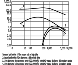
Although LHG is colourless, when released in air its vapours will be noticeable due to the condensation and freezing of water vapour contained in the atmosphere which is contacted by the vapour. This may not occur if the vapour is near ambient temperature and its pressure is relatively low. Instruments are available which can detect the presence of leaking LHG and signal an alarm at levels as low as 15 to 20% of the lower flammable limit (LFL). These devices may also stop all operations and activate suppression systems, should the concentrations of gas reach 40 to 50% of the LFL. Some industrial operations provide forced ventilation to keep leaking fuel-air concentrations below the lower flammable limit. Heater and furnace burners may also have devices which automatically stop the flow of gas if the flame is extinguished.
LHG leakage from tanks and containers may be minimized by the use of limiting and flow control devices. When decompressed and released, LHG will flow out of containers with a low negative pressure and low temperature. The auto refrigeration temperature of the product at the lower pressure must be considered when selecting materials of construction for containers and valves, to prevent metal embrittlement followed by rupture or failure due to exposure to low temperatures.
LHG can contain water in both its liquid and gaseous phases. Water vapour can saturate gas in a specific amount at a given temperature and pressure. If the temperature or pressure changes, or the water vapour content exceeds the evaporation limits, the water condenses. This can create ice plugs in valves and regulators and form hydrocarbon hydrate crystals in pipelines, devices and other apparatus. These hydrates can be decomposed by heating the gas, lowering the gas pressure or introducing materials, such as methanol, which reduce the water vapour pressure.
There are differences in the characteristics of compressed and liquefied gases which must be considered from safety, health and fire aspects. As an example, the differences in the characteristics of compressed natural gas and LNG are illustrated in table 2.
Table 2. Comparison of characteristics of compressed and liquified gas.
|
Type gas |
Flammable range |
Heat release rate (BTU/gal) |
Storage condition |
Fire risks |
Health risks |
|
Compressed natural gas |
5.0–15 |
19,760 |
Gas at 2,400 to 4,000 psi |
Flammable gas |
Asphyxiant; overpressure |
|
LNG |
4.5–14 |
82,450 |
Liquid at 40–140 psi |
Flammable gas 625:1 expansion ratio; BLEVE |
Asphyxiant; cryogenic liquid |
Health hazards of LHGs
The primary occupational injury concern in handling LHGs is the potential hazard of frostbite to the skin and eyes from contact with liquid during handling and storage activities including sampling, measuring, filling, receiving and delivery. As with other fuel gases, when improperly burned, compressed and liquefied hydrocarbon gases will emit undesirable levels of carbon monoxide.
Under atmospheric pressures and low concentrations, compressed and liquefied hydrocarbon gases are normally non-toxic, but they are asphyxiants—they will displace oxygen (air) if released in enclosed or confined spaces. Compressed and liquefied hydrocarbon gases may be toxic if they contain sulphur compounds, especially hydrogen sulphide. Because LHGs are colourless and odourless, safeguards include adding odourants, such as mercaptans, to consumer fuel gases to aid in leak detection. Safe work practices should be implemented to protect workers from exposure to mercaptans and other additives during storage and injection. Exposure to LPG vapours in concentrations at or above the LFL may cause a general central nervous system depression similar to anaesthesia gases or intoxicants.
Fire hazards of LHGs
Failure of liquefied gas (LNG and LPG) containers constitutes a more severe hazard than failure of compressed gas containers, as they release greater quantities of gas. When heated, liquefied gases react differently from compressed gases, because they are two-phase (liquid-vapour) products. As the temperature rises, the vapour pressure of the liquid is increased, resulting in increased pressure inside the container. The vapour phase first expands, followed by expansion of the liquid, which then compresses the vapour. The design pressure for LHG vessels is therefore assumed to be near that of the gas pressure at maximum possible ambient temperature.
When a liquefied gas container is exposed to fire, a serious condition can occur if the metal in the vapour space is allowed to heat. Unlike the liquid phase, the vapour phase absorbs little heat. This allows the metal to heat rapidly until a critical point is reached at which an instantaneous, catastrophic explosive failure of the container occurs. This phenomenon is known as a BLEVE. The magnitude of a BLEVE depends on the amount of liquid vaporizing when the container fails, the size of the pieces of exploded container, the distance they travel and the areas they impact. Uninsulated LPG containers may be protected against a BLEVE by applying cooling water to those areas of the container which are in the vapour phase (not in contact with LPG).
Other more common fire hazards associated with compressed and liquefied hydrocarbon gases include electrostatic discharge, combustion explosions, large open-air explosions and small leaks from pump seals, containers, valves, pipes, hoses and connections.
- Electrostatic charges may be generated when LHG is shipped in pipelines, when loaded and unloaded, in blending and filtering and during tank cleaning.
- Combustion explosions result when escaping gas or vapour is contained in a confined space or structure and combines with air to create a flammable mixture. When this flammable mixture contacts a source of ignition, it burns instantaneously and rapidly, producing extreme heat. The very hot air expands quickly, causing a considerable rise in pressure. If the space or structure is not strong enough to contain this pressure, a combustion explosion occurs.
- Flammable gas fires result when there is no confinement of the escaping gas or vapours, or ignition occurs when only a small amount of gas has been released.
- Large open-air explosions occur when a massive failure of a container releases a large vapour cloud of gas which is ignited before it disperses.
Controlling sources of ignition in hazardous areas is essential for the safe handling of compressed and liquefied hydrocarbon gases. This may be accomplished by establishing a permit system to authorize and control hot work, smoking, operation of motor vehicles or other internal combustion engines, and the use of open flames in areas where compressed and liquefied hydrocarbon gas is transported, stored and handled. Other safeguards include the use of properly classified electrical equipment and bonding and grounding systems to neutralize and dissipate static electricity.
The best means of reducing the fire hazard of leaking compressed or liquefied hydrocarbon gas is to stop the release, or shut off the flow of product, if possible. Although most LHGs will vaporize upon contact with air, lower vapour pressure LPGs, such as butane, and even some higher vapour pressure LPGs, such as propane, will pool if ambient temperatures are low. Water should not be applied to these pools, as it will create turbulence and increase the rate of vaporization. Vaporization from pool spills can be controlled by the careful application of foam. Water, if correctly applied against a leaking valve or small rupture, can freeze upon contact with the cold LHG and block the leak. LHG fires require controlling heat impingement upon storage tanks and containers by the application of cooling water. While compressed and liquefied hydrocarbon gas fires can be extinguished by the use of water spray and dry powder extinguishers, it is often more prudent to allow controlled burning so that a combustible explosive vapour cloud does not form and re-ignite should the gas continue to escape after the fire is extinguished.
Water Transportation and the Maritime Industries
The very definition of the maritime setting is work and life that takes place in or around a watery world (e.g., ships and barges, docks and terminals). Work and life activities must first accommodate the macro-environmental conditions of the oceans, lakes or waterways in which they take place. Vessels serve as both workplace and home, so most habitat and work exposures are coexistent and inseparable.
The maritime industry comprises a number of sub-industries, including freight transportation, passenger and ferry service, commercial fishing, tankships and barge shipping. Individual maritime sub-industries consist of a set of merchant or commercial activities that are characterized by the type of vessel, targeted goods and services, typical practices and area of operations, and community of owners, operators and workers. In turn, these activities and the context in which they take place define the occupational and environmental hazards and exposures experienced by maritime workers.
Organized merchant maritime activities date back to the earliest days of civilized history. The ancient Greek, Egyptian and Japanese societies are examples of great civilizations where the development of power and influence was closely associated with having an extensive maritime presence. The importance of maritime industries to development of national power and prosperity has continued into the modern era.
The dominant maritime industry is water transportation, which remains the primary mode of international trade. The economies of most countries with ocean borders are heavily influenced by the receipt and export of goods and services by water. However, national and regional economies heavily dependent on the transport of goods by water are not limited to those which border oceans. Many countries removed from the sea have extensive networks of inland waterways.
Modern merchant vessels may process materials or produce goods as well as transport them. Globalized economies, restrictive land use, favourable tax laws and technology are among the factors which have spurred the growth of vessels that serve as both factory and means of transportation. Catcher-processor fishing vessels are a good example of this trend. These factory ships are capable of catching, processing, packaging and delivering finished sea food products to regional markets, as discussed in the chapter Fishing industry.
Merchant Transport Vessels
Similar to other transport vehicles, the structure, form and function of vessels closely parallel the vessel’s purpose and major environmental circumstances. For example, craft that transport liquids short distances on inland waterways will differ substantially in form and crew from those that carry dry bulk on trans-oceanic voyages. Vessels can be free moving, semi-mobile or permanently fixed structures (e.g., offshore oil-drilling rigs) and be self-propelled or towed. At any given time, existing fleets are comprised of a spectrum of vessels with a wide range of original construction dates, materials and degrees of sophistication.
Crew size will depend on the typical duration of trip, vessel purpose and technology, expected environmental conditions and sophistication of shore facilities. Larger crew size entails more extensive needs and elaborate planning for berthing, dining, sanitation, health care and personnel support. The international trend is toward vessels of increasing size and complexity, smaller crews and expanding reliance on automation, mechanization and containerization. Table 1 provides a categorization and descriptive summary of merchant vessel types.
Table 1. Merchant vessel types.
|
Vessel types |
Description |
Crew size |
|
Freight ships |
||
|
Bulk carrier
Break bulk
Container
Ore, bulk, oil (OBO)
Vehicle
Roll-on roll- off (RORO) |
Large vessel (200-600 feet (61-183 m)) typified by large open cargo holds and many voids; carry bulk cargoes such as grain and ore; cargo is loaded by chute, conveyor or shovel
Large vessel (200-600 feet (61-183 m)); cargo carried in bales, pallets, bags or boxes; expansive holds with between decks; may have tunnels
Large vessel (200-600 (61-183 m)) with open holds; may or may not have booms or cranes to handle cargo; containers are 20-40 feet (6.1-12.2 m) and stackable
Large vessel (200-600 feet (61-183 m)); holds are expansive and shaped to hold bulk ore or oil; holds are water tight, may have pumps and piping; many voids
Large vessel (200-600 feet (61-183 m)) with big sail area; many levels; vehicles can be self loading or boomed aboard
Large vessel (200-600 feet (61-183 m)) with big sail area; many levels; can carry other cargo in addition to vehicles |
25-50
25-60
25-45
25-55
25-40
25-40 |
|
Tank ships |
||
|
Oil
Chemical
Pressurized |
Large vessel (200-1000 feet (61-305 m)) typified by stern house piping on deck; may have hose handling booms and large ullages with many tanks; can carry crude or processed oil, solvents and other petroleum products
Large vessel (200-1000 feet (61-305 m)) similar to oil tankship, but may have additional piping and pumps to handle multiple cargoes simultaneously; cargoes can be liquid, gas, powders or compressed solids
Usually smaller (200-700 feet (61-213.4 m)) than typical tankship, having fewer tanks, and tanks which are pressurized or cooled; can be chemical or petroleum products such as liquid natural gas; tanks are usually covered and insulated; many voids, pipes and pumps |
25-50
25-50
15-30
|
|
Tug boats |
Small to mid-size vessel (80-200 feet (24.4-61 m)); harbour, push boats, ocean going |
3-15 |
|
Barge |
Mid-size vessel (100-350 feet (30.5-106.7 m)); can be tank, deck, freight or vehicle; usually not manned or self-propelled; many voids |
|
|
Drillships and rigs |
Large, similar profile to bulk carrier; typified by large derrick; many voids, machinery, hazardous cargo and large crew; some are towed, others self propelled |
40-120 |
|
Passenger |
All sizes (50-700 feet (15.2-213.4 m)); typified by large number of crew and passengers (up to 1000+) |
20-200 |
Morbidity and Mortality in the Maritime Industries
Health care providers and epidemiologists are often challenged to distinguish adverse health states due to work-related exposures from those due to exposures outside the workplace. This difficulty is compounded in the maritime industries because vessels serve as both workplace and home, and both exist in the greater environment of the maritime milieu itself. The physical boundaries found on most vessels result in close confinement and sharing of workspaces, engine-room, storage areas, passageways and other compartments with living spaces. Vessels often have a single water, ventilation or sanitation system that serves both work and living quarters.
The social structure aboard vessels is typically stratified into vessel officers or operators (ship’s master, first mate and so on) and remaining crew. Ship officers or operators are generally relatively more educated, affluent and occupationally stable. It is not uncommon to find vessels with crew members of an entirely different national or ethnic background from that of the officers or operators. Historically, maritime communities are more transient, heterogeneous and somewhat more independent than non-maritime communities. Work schedules aboard ship are often more fragmented and intermingled with non-work time than are land-based employment situations.
These are some reasons why it is difficult to describe or quantify health problems in the maritime industries, or to correctly associate problems with exposures. Data on maritime worker morbidity and mortality suffer from being incomplete and not representative of entire crews or sub-industries. Another shortfall of many data sets or information systems that report on the maritime industries is the inability to distinguish among health problems due to work, vessel or macro-environmental exposures. As with other occupations, difficulties in capturing morbidity and mortality information is most obvious with chronic disease conditions (e.g., cardiovascular disease), particularly those with a long latency (e.g., cancer).
Review of 11 years (1983 to 1993) of US maritime data demonstrated that half of all fatalities due to maritime injuries, but only 12% of non-fatal injuries, are attributed to the vessel (i.e., collision or capsizing). The remaining fatalities and non-fatal injuries are attributed to personnel (e.g., mishaps to an individual while aboard ship). Reported causes of such mortality and morbidity are described in figure 1 and figure 2 respectively. Comparable information on non-injury-related mortality and morbidity is not available.
Figure 1. Causes of leading fatal unintentional injuries attributed to personal reasons (US maritime industries 1983-1993).
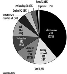
Figure 2. Causes of leading non-fatal unintentional injuries attributed to personal reasons (US maritime industries 1983-1993).
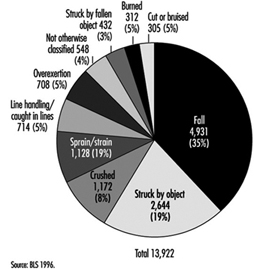
Combined vessel and personal US maritime casualty data reveal that the highest proportion (42%) of all maritime fatalities (N = 2,559), occurred among commercial fishing vessels. The next highest were among towboats/barges (11%), freight ships (10%) and passenger vessels (10%).
Analysis of reported work-related injuries for the maritime industries shows similarities to patterns reported for the manufacturing and construction industries. Commonalities are that most injuries are due to falls, being struck, cuts and bruises or muscular strains and overuse. Caution is needed when interpreting these data, however, as there is reporting bias: acute injuries are likely to be over-represented and chronic/latent injuries, which are less obviously connected to work, under-reported.
Occupational and Environmental Hazards
Most health hazards found in the maritime setting have land-based analogs in the manufacturing, construction and agricultural industries. The difference is that the maritime environment constricts and compresses available space, forcing close proximity of potential hazards and the intermingling of living quarters and workspaces with fuel tanks, engine and propulsion areas, cargo and storage spaces.
Table 2 summaries health hazards common across different vessel types. Health hazards of particular concern with specific vessel types are highlighted in table 3. The following paragraphs of this section expand discussion of selected environmental, physical and chemical, and sanitation health hazards.
Table 2. Health hazards common across vessel types.
|
Hazards |
Description |
Examples |
|
Mechanical |
Unguarded or exposed moving objects or their parts, which strike, pinch, crush or entangle. Objects can be mechanized (e.g., fork-lift) or simple (hinged door). |
Winches, pumps, fans, drive shafts, compressors, propellers, hatches, doors, booms, cranes, mooring lines, moving cargo |
|
Electrical |
Static (e.g., batteries) or active (e.g., generators) sources of electricity, their distribution system (e.g., wiring) and powered devices (e.g., motors), all of which can cause direct electrical-induced physical injury |
Batteries, vessel generators, dockside electrical sources, unprotected or ungrounded electric motors (pumps, fans, etc.), exposed wiring, navigation and communication electronics |
|
Thermal |
Heat- or cold-induced injury |
Steam pipes, cold storage spaces, power plant exhaust, cold- or warm-weather exposure above deck |
|
Noise |
Adverse auditory and other physiological problems due to excessive and prolonged sound energy |
Vessel propulsion system, pumps, ventilation fans, winches, steam-powered devices, conveyor belts |
|
Fall |
Slips, trips and falls resulting in kinetic-energy-induced injuries |
Steep ladders, deep vessel holds, missing railings, narrow gangways, elevated platforms |
|
Chemical |
Acute and chronic disease or injury resulting from exposure to organic or inorganic chemicals and heavy metals |
Cleaning solvents, cargo, detergents, welding, rusting/corrosion processes, refrigerants, pesticides, fumigants |
|
Sanitation |
Disease related to unsafe water, poor food practices or improper waste disposal |
Contaminated potable water, food spoilage, deteriorated vessel waste system |
|
Biologic |
Disease or illness causes by exposure to living organisms or their products |
Grain dust, raw wood products, cotton bales, bulk fruit or meat, seafood products, communicable disease agents |
|
Radiation |
Injury due to non-ionizing radiation |
Intense sunlight, arc welding, radar, microwave communications |
|
Violence |
Interpersonal violence |
Assault, homicide, violent conflict among crew |
|
Confined space |
Toxic or anoxic injury resulting from entering an enclosed space with limited entry |
Cargo holds, ballast tanks, crawl spaces, fuel tanks, boilers, storage rooms, refrigerated holds |
|
Physical work |
Health problems due to overuse, disuse or unsuitable work practices |
Shovelling ice in fish tanks, moving awkward cargo in restricted spaces, handling heavy mooring lines, prolonged stationary watch standing |
Table 3. Notable physical and chemical hazards for specific vessel types.
|
Vessel Types |
Hazards |
|
Tank vessels |
Benzene and various hydrocarbon vapours, hydrogen sulphide off-gassing from crude oil, inert gases used in tanks to create oxygen-deficient atmosphere for explosion control, fire and explosion due to combustion of hydrocarbon products |
|
Bulk cargo vessels |
Pocketing of fumigants used on agricultural products, personnel entrapment/suffocation in loose or shifting cargo, confined space risks in conveyor or man tunnels deep in vessel, oxygen deficiency due to oxidation or fermentation of cargo |
|
Chemical carriers |
Venting of toxic gases or dusts, pressurized air or gas release, leakage of hazardous substances from cargo holds or transfer pipes, fire and explosion due to combustion of chemical cargoes |
|
Container ships |
Exposure to spills or leakage due to failed or improperly stored hazardous substances; release of agricultural inerting gases; venting from chemical or gas containers; exposure to mislabeled substances that are hazardous; explosions, fire or toxic exposures due to mixing of separate substances to form a dangerous agent (e.g., acid and sodium cyanide) |
|
Break bulk vessels |
Unsafe conditions due to shifting of cargo or improper storage; fire, explosion or toxic exposures due to mixing of incompatible cargoes; oxygen deficiency due to oxidation or fermentation of cargoes; release of refrigerant gases |
|
Passenger ships |
Contaminated potable water, unsafe food preparation and storage practices, mass evacuation concerns, acute health problems of individual passengers |
|
Fishing vessels |
Thermal hazards from refrigerated holds, oxygen deficiency due to decomposition of seafood products or use of antioxidant preservatives, release of refrigerant gases, entanglement in netting or lines, contact with dangerous or toxic fish or sea animals |
Environmentalhazards
Arguably the most characteristic exposure defining the maritime industries is the pervasive presence of the water itself. The most variable and challenging of water environments is the open ocean. Oceans present constantly undulating surfaces, extremes of weather and hostile travel conditions, which combine to cause constant motion, turbulence and shifting surfaces and can result in vestibular disturbances (motion sickness), object instability (e.g., swinging latches and sliding gear) and the propensity to fall.
Humans have limited capability to survive unaided in open water; drowning and hypothermia are immediate threats upon immersion. Vessels serve as platforms that permit the human presence at sea. Ships and other water craft generally operate at some distance from other resources. For these reasons, vessels must dedicate a large proportion of total space to life support, fuel, structural integrity and propulsion, often at the expense of habitability, personnel safety and human factor considerations. Modern supertankers, which provide more generous human space and liveability, are an exception.
Excessive noise exposure is a prevalent problem because sound energy is readily transmitted through a vessel’s metallic structure to nearly all spaces, and limited noise attenuation materials are used. Excessive noise can be nearly continuous, with no available quiet areas. Sources of noise include the engine, propulsion system, machinery, fans, pumps and the pounding of waves on the vessel hull.
Mariners are an identified risk group for developing skin cancers, including malignant melanoma, squamous cell carcinoma and basal cell carcinoma. The increased risk is due to excess exposure to direct and water-surface-reflected ultraviolet solar radiation. Body areas of particular risk are exposed parts of the face, neck, ears and forearms.
Limited insulation, inadequate ventilation, internal sources of heat or cold (e.g., engine rooms or refrigerated spaces) and metallic surfaces all account for potential thermal stress. Thermal stress compounds physiological stress from other sources, resulting in reduced physical and cognitive performance. Thermal stress that is not adequately controlled or protected against can result in heat- or cold-induced injury.
Physical and chemical hazards
Table 3 highlights hazards unique or of particular concern to specific vessel types. Physical hazards are the most common and pervasive hazard aboard vessels of any type. Space limitations result in narrow passageways, limited clearance, steep ladders and low overheads. Confined vessel spaces means that machinery, piping, vents, conduits, tanks and so forth are squeezed in, with limited physical separation. Vessels commonly have openings that allow direct vertical access to all levels. Inner spaces below the surface deck are characterized by a combination of large holds, compact spaces and hidden compartments. Such physical structure places crew members at risk for slips, trips and falls, cuts and bruises, and being struck by moving or falling objects.
Constricted conditions result in being in close proximity to machinery, electrical lines, high-pressure tanks and hoses, and dangerously hot or cold surfaces. If unguarded or energized, contact can result in burns, abrasions, lacerations, eye damage, crushing or more serious injury.
Since vessels are basically a composite of spaces housed within a water-tight envelope, ventilation can be marginal or deficient in some spaces, creating a hazardous confined space situation. If oxygen levels are depleted or air is displaced, or if toxic gases enter these confined spaces, entry can be life threatening.
Refrigerants, fuels, solvents, cleaning agents, paints, inert gases and other chemical substances are likely to be found on any vessel. Normal ship activities, such as welding, painting and trash burning can have toxic effects. Transport vessels (e.g., freight ships, container ships and tank ships) can carry a host of biological or chemical products, many of which are toxic if inhaled, ingested or touched with the bare skin. Others can become toxic if allowed to degrade, become contaminated or mix with other agents.
Toxicity can be acute, as evidenced by dermal rashes and ocular burns, or chronic, as evidenced by neurobehavioural disorders and fertility problems or even carcinogenic. Some exposures can be immediately life-threatening. Examples of toxic chemicals carried by vessels are benzene-containing petrochemicals, acrylonitrile, butadiene, liquefied natural gas, carbon tetrachloride, chloroform, ethylene dibromide, ethylene oxide, formaldehyde solutions, nitropropane, o-toluidine and vinyl chloride.
Asbestos remains a hazard on some vessels, principally those constructed prior to the early 1970s. The thermal insulation, fire protection, durability and low cost of asbestos made this a preferred material in ship building. The primary hazard of asbestos occurs when the material becomes airborne when it is disturbed during renovations, construction or repair activities.
Sanitation and communicable disease hazards
One of the realities aboard ship is that the crew is often in close contact. In the work, recreation and living environments, crowding is often a fact of life that heightens the requirement for maintaining an effective sanitation programme. Critical areas include: berthing spaces, including toilet and shower facilities; food service and storage areas; laundry; recreation areas; and, if present, the barbershop. Pest and vermin control is also of critical importance; many of these animals can transmit disease. There are many opportunities for insects and rodents to infest a vessel, and once entrenched they are very difficult to control or eradicate, especially while underway. All vessels must have a safe and effective pest control programme. This requires training of individuals for this task, including annual refresher training.
Berthing areas must be kept free of debris, soiled laundry and perishable food. Bedding should be changed at least weekly (more often if soiled), and adequate laundry facilities for the size of the crew should be available. Food service areas must be rigorously maintained in a sanitary manner. The food service staff must receive training in proper techniques of food preparation, storage and galley sanitation, and adequate storage facilities must be provided aboard ship. The staff must adhere to recommended standards to ensure that food is prepared in a wholesome manner and is free of chemical and biological contamination. The occurrence of a food-borne disease outbreak aboard a vessel can be serious. A debilitated crew cannot carry out its duties. There may be insufficient medication to treat the crew, especially underway, and there may not be competent medical staff to care for the ill. In addition, if the ship is forced to change its destination, there may be significant economic loss to the shipping company.
The integrity and maintenance of a vessel’s potable water system is also of vital importance. Historically, water-borne outbreaks aboard ship have been the most common cause of acute disability and death among crews. Therefore, the potable water supply must come from an approved source (wherever possible) and be free from chemical and biological contamination. Where this is not possible, the vessel must have the means to effectively decontaminate the water and render it potable. A potable water system must be protected against contamination by every known source, including cross-contaminations with any non-potable liquids. The system also must be protected from chemical contamination. It must be cleaned and disinfected periodically. Filling the system with clean water containing at least 100 parts per million (ppm) of chlorine for several hours and then flushing the entire system with water containing 100 ppm chlorine is effective disinfection. The system should then be flushed with fresh potable water. A potable water supply must have at least 2 ppm residual of chlorine at all times, as documented by periodic testing.
Communicable disease transmission aboard ship is a serious potential problem. Lost work time, the cost of medical treatment and the possibility of having to evacuate crew members make this an important consideration. Besides the more common disease agents (e.g., those that cause gastroenteritis, such as Salmonella, and those that cause upper respiratory disease, such as the influenza virus), there has been a re-emergence of disease agents that were thought to be under control or eliminated from the general population. Tuberculosis, highly pathogenic strains of Escherichia coli and Streptococcus, and syphilis and gonorrhoea have reappeared in increasing incidence and/or virulence.
In addition, previously unknown or uncommon disease agents such as the HIV virus and the Ebola virus, which are not only highly resistant to treatment, but highly lethal, have appeared. It is therefore important that assessment be made of appropriate crew immunization for such diseases as polio, diphtheria, tetanus, measles, and hepatitis A and B. Additional immunizations may be required for specific potential or unique exposures, since crew members may have occasion to visit a wide variety of ports around the world and at the same time come in contact with a number of disease agents.
It is vital that crew members receive periodic training in the avoidance of contact with disease agents. The topic should include blood-borne pathogens, sexually transmitted diseases (STDs), food- and water-borne diseases, personal hygiene, symptoms of the more common communicable diseases and appropriate action by the individual on discovering these symptoms. Communicable disease outbreaks aboard ship can have a devastating effect on the vessel’s operation; they can result in a high level of illness among the crew, with the possibility of serious debilitating disease and in some cases death. In some instances, vessel diversion has been required with resultant heavy economic losses. It is in the best interest of the vessel owner to have an effective and efficient communicable disease programme.
Hazard Control and Risk Reduction
Conceptually, the principles of hazard control and risk reduction are similar to other occupational settings, and include:
- hazard identification and characterization
- inventory and analysis of exposures and at-risk populations
- hazard elimination or control
- personnel monitoring and surveillance
- disease/injury prevention and intervention
- programme evaluation and adjustment (see table 4).
Table 4. Vessel hazard control & risk-reduction.
|
Topics |
Activities |
|
Programme development and evaluation |
Identify hazards, shipboard and dockside. |
|
Hazard identification |
Inventory shipboard chemical, physical, biological, and environmental hazards, in both work and living spaces (e.g., broken railings, use and storage of cleaning agents, presence of asbestos). |
|
Assessment of exposure |
Understand work practices and job tasks (prescribed as well as those actually done). |
|
Personnel at risk |
Review work logs, employment records and monitoring data of entire ship’s complement, both seasonal and permanent. |
|
Hazard control and |
Know established and recommended exposure standards (e.g., NIOSH, ILO, EU). |
|
Health surveillance |
Develop health information gathering and reporting system for all injuries and illnesses (e.g., maintain a ship’s daily binnacle). |
|
Monitor crew health |
Establish occupational medical monitoring, determine performance standards, and establish fitness-for-work criteria (e.g., pre-placement and periodic pulmonary testing of crew handling grain). |
|
Hazard control and risk reduction effectiveness |
Devise and set priorities for goals (e.g., reduce shipboard falls). |
|
Programme evolution |
Modify prevention and control activities based on changing circumstances and prioritization. |
To be effective, however, the means and methods to implement these principles must be tailored to the specific maritime arena of interest. Occupational activities are complex and take place in integrated systems (e.g., vessel operations, employee/employer associations, commerce and trade determinants). The key to prevention is to understand these systems and the context in which they take place, which requires close cooperation and interaction between all organizational levels of the maritime community, from general deck hand through vessel operators and company upper management. There are many government and regulatory interests that impact the maritime industries. Partnerships between government, regulators, management and workers are essential for meaningful programmes for improving the health and safety status of the maritime industries.
The ILO has established a number of Conventions and Recommendations relating to shipboard work, such as the Prevention of Accidents (Seafarers) Convention, 1970 (No. 134), and Recommendation, 1970 (No. 142), the Merchant Shipping (Minimum Standards) Convention, 1976 (No. 147), the Merchant Shipping (Improvement of Standards) Recommendation, 1976 (No. 155), and the Health Protection and Medical Care (Seafarers) Convention, 1987 (No. 164). The ILO has also published a Code of Practice regarding the prevention of accidents at sea (ILO 1996).
Approximately 80% of vessel casualties are attributed to human factors. Similarly, the majority of reported injury-related morbidity and mortality have human factor causes. Reduction in maritime injury and death requires successful application of principles of human factors to work and life activities aboard vessels. Successful application of human factors principles means that vessel operations, vessel engineering and design, work activities, systems and management policies are developed that integrate human anthropometrics, performance, cognition and behaviours. For example, cargo loading/unloading presents potential hazards. Human factor considerations would highlight the need for clear communication and visibility, ergonomic matching of worker to task, safe separation of workers from moving machinery and cargo and a trained workforce, well acquainted with work processes.
Prevention of chronic diseases and adverse health states with long latency periods is more problematic than injury prevention and control. Acute injury events generally have readily recognized cause-effect relationships. Also, the association of injury cause and effect with work practices and conditions is usually less complicated than for chronic diseases. Hazards, exposures and health data specific to the maritime industries are limited. In general, health surveillance systems, reporting and analyses for the maritime industries are less developed than those for many of their land-based counterparts. The limited availability of chronic or latent disease health data specific to maritime industries hinders development and application of targeted prevention and control programmes.
Subways
While railroad safety comes under the jurisdiction of national governments, which issue rules and policies for safety governance and enforcement, subways are usually governed by local public authorities, which in essence govern themselves.
Subway fares usually do not cover operating cost and, through subsidies, are kept at certain levels to maintain an affordable public transportation service. Subway and other city mass transit systems make city roads more accessible and reduce the pollution associated with urban automobile traffic.
Budget cuts that have become so common in many countries in recent years also affect mass transit systems. Preventive maintenance personnel and the upgrade of tracks, signals and rolling stock are the first to be affected. The controlling authorities are often unwilling or unable to enforce their own regulatory procedures on a rapid transit system abandoned by government subsidies. Inevitably in such circumstances, a transportation accident with catastrophic loss of life during the budget cuts results in a public outcry demanding improvements in safety.
While it is recognized that great variation exists in the design, construction and age of the physical facilities of the rapid transit properties in Canada, the United States and other countries, certain standard maintenance functions must be carried out to keep operating track, aerial and underground structures, passenger stations and related facilities in the safest possible condition.
Subway Operation and Maintenance
Subways differ from railroads in several basic ways:
- most subways run underground in tunnels
- subways run on electricity rather than diesel or steam (although there are also some electrical trains)
- subways run much more frequently than railroad trains
- graffiti removal is a major problem.
These factors influence the degree of risk for subway train operators and maintenance crews.
Collisions between subway trains on the same track and with maintenance crews on the track are a serious problem. These collisions are controlled by proper scheduling, central communications systems to alert subway train operators of problems and signal light systems indicating when operators can proceed safely. Breakdowns in these control procedures resulting in collisions can occur due to radio communication problems, broken or improperly placed signal lights that do not give operators adequate time to stop and fatigue problems from shift work and excessive overtime, resulting in inattention.
Maintenance crews patrol the subway tracks doing repairs to tracks, signal lights and other equipment, picking up rubbish and performing other duties. They face electrical hazards from the third rail carrying the electricity to operate the subways, fire and smoke hazards from burning rubbish and possible electrical fires, inhalation hazards from steel dust and other particulates in the air from the subway wheels and rails and the hazard of being hit by subway cars. Floods in subways can also create electrical shock and fire hazards. Because of the nature of subway tunnels, many of these hazardous situations are confined-space hazards.
Adequate ventilation to remove air contaminants, proper confined-space and other emergency procedures (e.g., evacuation procedures) for fires and floods and adequate communication procedures including radios and signal lights to notify subway train operators of the presence of maintenance crews on the tracks are essential to protect these crews. There should be frequent emergency spaces along subway walls or adequate space between tracks to allow maintenance crew members to avoid passing subway cars.
Graffiti removal from both the inside and outside of subway cars is a hazard in addition to regular painting and cleaning of cars. Graffiti removers often contained strong alkalis and hazardous solvents and can be a hazard both by skin contact and inhalation. Exterior graffiti removal is done by driving the cars through a car wash where the chemicals are sprayed on the exterior of the car. The chemicals are also applied by brushing and spraying inside subway cars. Applying hazardous graffiti removers inside cars could be a confined-space hazard.
Precautions include using the least toxic chemicals possible, proper respirator protection and other personal protective equipment and proper procedures to ensure that car operators know what chemicals are being used.
Rail Operations
Railroads provide a major mode of transportation around the world. Today, even with competition from road and airborne transport, rail remains an important means of land-based movement of bulk quantities of goods and materials. Railroad operations are carried out in an enormously wide variety of terrains and climates, from Arctic permafrost to equatorial jungle, from rainforest to desert. The roadbed of partly crushed stone (ballast) and track consisting of steel rails and ties of wood, concrete or steel are common to all railroads. Ties and ballast maintain the position of the rails.
The source of power used in railroad operations worldwide (steam, diesel-electric and current electricity) spans the history of development of this mode of transportation.
Administration and Train Operations
Administration and train operations create the public profile of the railroad industry. They ensure that goods move from origin to destination. Administration includes office personnel involved in business and technical functions and management. Train operations include dispatchers, rail traffic control, signal maintainers, train crews and yard workers.
Dispatchers ensure that a crew is available at the appropriate point and time. Railroads operate 24 hours per day, 7 days per week throughout the year. Rail traffic control personnel coordinate train movements. Rail traffic control is responsible for assigning track to trains in the appropriate sequence and time. This function is complicated by single sets of track that must be shared by trains moving in both directions. Since only one train can occupy a particular section of track at any time, rail traffic control must assign occupancy of the main line and sidings, in a manner that assures safety and minimizes delay.
Signals provide visual cues to train operators, as well as to drivers of road vehicles at level train crossings. For train operators, signals must provide unambiguous messages about the status of the track ahead. Signals today are used as an adjunct to rail traffic control, the latter being conducted by radio on channels received by all operating units. Signal maintainers must ensure operation of these units at all times, which can sometimes involve working alone in remote areas in all weather at any time, day or night.
Yard workers’ duties include ensuring that the rolling stock is prepared to receive cargo, which is an increasingly important function in this era of quality management. Tri-level automobile transporter cars, for example, must be cleaned prior to use and readied to accept vehicles by moving chocks to appropriate positions. The distance between levels in these cars is too short for the average male to stand upright, so that work is done in a hunched over position. Similarly, the handholds on some cars force yard workers to assume an awkward posture during shunting operations.
For long runs, a train crew operates the train between designated transfer points. A replacement crew takes over at the transfer point and continues the journey. The first crew must wait at the transfer point for another train to make the return trip. The combined trips and the wait for the return train can consume many hours.
A train trip on single track can be very fragmented, in part because of problems in scheduling, track work and the breakdown of equipment. Occasionally a crew returns home in the cab of a trailing locomotive, in the caboose (where still in use) or even by taxi or bus.
The train crew’s duties may include dropping off some cars or picking up additional ones en route. This could occur at any hour of the day or night under any imaginable weather conditions. The assembly and disassembly of trains are the sole duties of some train crews in yards.
On occasion there is a failure of one of the knuckles that couple cars together or a break in a hose that carries braking system air between cars. This necessitates investigative work by one of the train crew and repair or replacement of the defective part. The spare knuckle (about 30 kg) must be carried along the roadbed to the repair point, and the original removed and replaced. Work between cars must reflect careful planning and preparation to ensure that the train does not move during the procedure.
In mountainous areas, breakdown may occur in a tunnel. The locomotive must maintain power above idle under these conditions in order to keep the braking functional and to prevent train runaway. Running the engine in a tunnel could cause the tunnel to fill with exhaust gases (nitrogen dioxide, nitric oxide, carbon monoxide and sulphur dioxide).
Table 1 summarizes potential hazardous conditions associated with administration and train operations.
Table 1. Hazardous conditions associated with administration and train operations.
|
Conditions |
Affected groups |
Comments |
|
Exhaust emissions |
Train crew, supervisors, technical advisors |
Emissions primarily include nitrogen dioxide, nitric oxide, carbon monoxide, sulphur dioxide and particulates containing polycyclic aromatic hydrocarbons (PAHs). Potential for exposure is most likely in unventilated tunnels. |
|
Noise |
Train crew, supervisors, technical advisors |
In-cab noise could exceed regulated limits. |
|
Whole-body vibration |
Train crew |
Structure-borne vibration transmitted through the floor and seats in the cab originates from the engine and motion along the track and over gaps between rails. |
|
Electromagnetic fields |
Train crew, signal maintainers |
AC and DC fields are possible, depending on design of power unit and traction motors. |
|
Radio-frequency fields |
Users of two-way radios |
Effects on humans are not fully established. |
|
Weather |
Train crew, yard workers, signal maintainers |
Ultraviolet energy can cause sunburn, skin cancer and cataracts. Cold can cause cold stress and frostbite. Heat can cause heat stress. |
|
Shiftwork |
Dispatchers, rail traffic control, train crews, signal maintainers |
Train crews can work irregular hours; remuneration is often based on travelling a fixed distance within a time period. |
|
Musculoskeletal injury |
Train crew, yard workers |
Ankle injury can occur during disembarkment from moving equipment. Shoulder injury can occur during embarkment onto moving equipment. Injury can occur at various sites while carrying knuckles on rough terrain. Work is performed in awkward postures. |
|
Video displays units |
Management, administrative and technical staff, dispatchers, rail traffic control |
Effective use of computerized workstations depends on application of visual and office ergonomic principles. |
|
Rundown accidents |
All workers |
Rundown can occur when the individual stands on an active track and fails to hear approach of trains, track equipment and moving cars. |
Maintenance of Rolling Stock and Track Equipment
Rolling stock includes locomotives and railcars. Track equipment is specialized equipment used for track patrol and maintenance, construction and rehabilitation. Depending on the size of the railroad, maintenance can range from onsite (small-scale repairs) to complete stripdown and rebuilding. Rolling stock must not fail in operation, since failure carries serious adverse safety, environmental and business consequences. If a car carries a hazardous commodity, the consequences that can arise from failure to find and repair a mechanical defect can be enormous.
Larger rail operations have running shops and centralized stripdown and rebuild facilities. Rolling stock is inspected and prepared for the trip at running shops. Minor repair is performed on both cars and locomotives.
Railcars are rigid structures that have pivot points near each end. The pivot point accepts a vertical pin located in the truck (the wheels and their support structure). The body of the car is lifted from the truck for repairs. Minor repair can involve the body of the car or attachments or brakes or other parts of the truck. Wheels may require machining on a lathe to remove flat spots.
Major repair could include removal and replacement of damaged or corroded metal sheeting or frame and abrasive blasting and repainting. It could also include removal and replacement of wooden flooring. Trucks, including wheel-axle sets and bearings, may require disassembly and rebuilding. Rehabilitation of truck castings involves build-up welding and grinding. Rebuilt wheel-axle sets require machining to true the assembly.
Locomotives are cleaned and inspected prior to each trip. The locomotive may also require mechanical service. Minor repairs include oil changes, work on brakes and servicing of the diesel engine. Removal of a truck for wheel truing or evening may also be needed. Operation of the engine may be required in order to position the locomotive inside the service building or to remove it from the building. Prior to re-entry into service the locomotive could require a load test, during which the engine is operated at full throttle. Mechanics work in close proximity to the engine during this procedure.
Major servicing could involve complete stripdown of the locomotive. The diesel engine and engine compartment, compressor, generator and traction motors require thorough degreasing and cleaning owing to heavy service and contact of fuel and lubricants with hot surfaces. Individual components may then be stripped and rebuilt.
Traction motor casings may require build-up welding. Armatures and rotors may need machining in order to remove old insulation, then be repaired and impregnated with a solution of varnish.
Track maintenance equipment includes trucks and other equipment that can operate on road and rail, as well as specialized equipment that operates only on rail. The work may include highly specialized units, such as track inspection units or rail-grinding machines, which may be “one of a kind”, even in large railroad companies. Track maintenance equipment may be serviced in garage settings or in field locations. The engines in this equipment may produce considerable exhaust emissions due to long periods between service and lack of familiarity of mechanics. This can have major pollution consequences during operation in confined spaces, such as tunnels and sheds and enclosing formations.
Table 2 summarizes potential hazardous conditions associated with maintenance of rolling stock and track equipment as well as transportation accidents.
Table 2. Hazardous conditions associated with maintenance and transportation accidents.
|
Conditions |
Affected groups |
Comments |
|
Skin contamination with waste oils and lubricants |
Diesel mechanics, traction motor mechanics |
Decomposition of hydrocarbons in contact with hot surfaces can produce polycyclic aromatic hydrocarbons (PAHs). |
|
Exhaust emissions |
All workers in diesel shop, wash facility, refuelling area, load test area |
Emissions primarily include nitrogen dioxide, nitric oxide, carbon monoxide, sulphur dioxide and particulates containing (PAHs). Potential for exposure most likely where exhaust emissions are confined by structures. |
|
Welding emissions |
Welders, tackers, fitters, operators of overhead cranes |
Work primarily involves carbon steel; aluminium and stainless steel are possible. Emissions include shield gases and fluxes, metal fumes, ozone, nitrogen dioxide, visible and ultraviolet energy. |
|
Brazing emissions |
Electricians working on traction motors |
Emission include cadmium end lead in solder. |
|
Thermal decomposition products from coatings |
Welders, tackers, fitters, grinders, operators of overhead cranes |
Emissions can include carbon monoxide, inorganic pigments containing lead and other chromates, decomposition products from paint resins. PCBs may have been used prior to 1971. PCBs can form furans and dioxins when heated. |
|
Cargo residues |
Welders, fitters, tackers, grinders, mechanics, strippers |
Residues reflect service in which car was used; cargoes could include heavy metal concentrates, coal, sulphur, lead ingots, etc. |
|
Abrasive blasting dust |
Abrasive blaster, bystanders |
Dust can contain cargo residues, blast material, paint dust. Paint applied prior to 1971 may contain PCBs. |
|
Solvent vapours |
Painter, bystanders |
Solvent vapours can be present in paint storage and mixing areas and paint booth; flammable mixtures may develop inside confined spaces, such as hoppers and tanks, during spraying. |
|
Paint aerosols |
Painter, bystanders |
Paint aerosols contain sprayed paint plus diluent; solvent in droplets and vapour can form flammable mixtures; resin system can include isocyanates, epoxys, amines, peroxides and other reactive intermediates. |
|
Confined spaces |
All shop workers |
Interior of some railcars, tanks and hoppers, nose of locomotive, ovens, degreasers, varnish impregnator, pits, sumps and other enclosed and partially enclosed structures |
|
Noise |
All shop workers |
Noise generated by many sources and tasks can exceed regulated limits. |
|
Hand-arm vibration |
Users of powered hand tools and hand-held equipment |
Vibration is transmitted through hand grips. |
|
Electromagnetic fields |
Users of electrical welding equipment |
AC and DC fields are possible, depending on design of the unit. |
|
Weather |
Outside workers |
Ultraviolet energy can cause sunburn, skin cancer and cataracts. Cold can cause cold stress and frostbite. Heat can cause heat stress. |
|
Shiftwork |
All workers |
Crews can work irregular hours. |
|
Musculoskeletal injury |
All workers |
Ankle injury can occur during disembarkment from moving equipment. Shoulder injury can occur during embarkment onto moving equipment or climbing onto cars. Work is performed in awkward posture especially when welding, burning, cutting and operating powered hand tools. |
|
Rundown accidents |
All workers |
Rundown can occur when the individual stands on active track and fails to hear approach of track equipment and moving cars. |
Maintenance of Track and Right of Way
Maintenance of track and right of way primarily involves work in the outdoor environment in conditions associated with the outdoors: sun, rain, snow, wind, cold air, hot air, blowing sand, biting and stinging insects, aggressive animals, snakes and poisonous plants.
Track and right-of-way maintenance can include track patrol, as well as the maintenance, rehabilitation and replacement of buildings and structures, track and bridges, or service functions, such as snowplowing and herbicide application, and may involve local operating units or large, specialized work gangs that deal with replacement of rails, ballast or ties. Equipment is available to almost completely mechanize each of these activities. Small-scale work, however, could involve small, powered equipment units or even be a completely manual activity.
In order to carry out maintenance of operating lines, a block of time must be available during which the work can occur. The block could become available at any time of day or night, depending on train scheduling, especially on a single-track main line. Thus, time pressure is a main consideration during this work, since the line must be returned to service at the end of the assigned block of time. Equipment must proceed to the site, the work must be completed, and the track vacated within the set period.
Ballast replacement and tie and rail replacement are complex tasks. Ballast replacement first involves removal of contaminated or deteriorated material in order to expose the track. A sled, a plow-like unit that is pulled by a locomotive, or an undercutter performs this task. The undercutter uses a continuous toothed chain to pull ballast to the side. Other equipment is used to remove and replace rail spikes or tie clips, tie plates (the metal plate on which the rail sits on the tie) and ties. Continuous rail is akin to a noodle of wet spaghetti that can flex and whip and that is easily moved vertically and laterally. Ballast is used to stabilize the rail. The ballast train delivers new ballast and pushes it into position. Labourers walk along with the train and systematically open chutes located at the bottom of the cars in order to enable ballast to flow.
After the ballast is dropped, a tamper uses hydraulic fingers to pack the ballast around and under the ties and lifts the track. A spud liner drives a metal spike into the roadbed as an anchor and moves the track into the desired position. The ballast regulator grades the ballast to establish the final contours of the roadbed and sweeps clean the surface of the ties and rails. Considerable dust is generated during ballast dumping, regulating and sweeping.
There are a variety of settings in which track work can take place—open areas, semi-enclosed areas such as cuts, and hill and cliff faces and confined spaces, such as tunnels and sheds. These have a profound influence on working conditions. Enclosed spaces, for example, will confine and concentrate exhaust emissions, ballast dust, dust from grinding, fumes from thermite welding, noise and other hazardous agents and conditions. (Thermite welding uses powdered aluminium and iron oxide. Upon ignition the aluminium burns intensely and converts the iron oxide to molten iron. The molten iron flows into the gap between the rails, welding them together end to end.)
Switching structures are associated with track. The switch contains moveable, tapered rails (points) and a wheel guide (frog). Both are manufactured from specially hardened steel containing a high level of manganese and chromium. The frog is an assembled structure containing several pieces of specially bent rail. The self-locking nuts which are used to bolt together these and other track structures may be cadmium-plated. Frogs are built up by welding and are ground during refurbishing, which can occur onsite or in shop facilities.
Bridge repainting is also an important part of right-of-way maintenance. Bridges often are situated in remote locations; this can considerably complicate provision of personal hygiene facilities which are needed to prevent contamination of individuals and the environment.
Table 3 summarizes the hazards of track and right-of-way maintenance.
Transportation Accidents
Possibly the greatest single concern in rail operations is the transportation accident. The large quantities of material that could be involved could cause serious problems of exposure of personnel and the environment. No amount of preparation for a worst-case accident is ever enough. Therefore, minimizing risk and the consequences of an accident are imperative. Transportation accidents occur for a variety of reasons: collisions at level crossings, obstruction of the track, failure of equipment and operator error.
The potential for such accidents can be minimized through conscientious and ongoing inspection and maintenance of track and right-of-way and equipment. The impact of a transportation accident involving a train carrying mixed cargo can be minimized through strategic positioning of cars that carry incompatible freight. Such strategic positioning, however, is not possible for a train hauling a single commodity. Commodities of particular concern include: pulverized coal, sulphur, liquefied petroleum (fuel) gases, heavy metal concentrates, solvents and process chemicals.
All of the groups in a rail organization are involved in transportation accidents. Rehabilitation activities can literally involve all groups working simultaneously at the same location on the site. Thus, coordination of these activities is extremely important, so that the actions of one group do not interfere with those of another.
Hazardous commodities generally remain contained during such accidents because of the attention given to crashproofing in the design of shipping containers and bulk rail cars. During an accident, the contents are removed from the damaged car by emergency response crews that represent the shipper. Equipment maintainers repair the damage to the extent possible and put the car back on the track, if possible. However, the track under the derailed car may have been destroyed. If so, repair or replacement of track occurs next, using prefabricated sections and techniques similar to those described above.
In some situations, loss of containment occurs and the contents of the car or shipping container spill onto the ground. If substances are shipped in quantities sufficient to require placarding because of transportation laws, they are readily identifiable on shipping manifests. However, highly hazardous substances that are shipped in smaller quantities than mandated for listing in a shipping manifest can escape identification and characterization for a considerable period. Containment at the site and collection of the spilled material are the responsibility of the shipper.
Railway personnel can be exposed to materials that remain in snow, soil or vegetation during rehabilitation efforts. The severity of exposure depends on the properties and quantity of the substance, the geometry of the site and weather conditions. The situation could also pose fire, explosion, reactivity and toxic hazards to humans, animals and the surrounding environment.
At some point following the accident, the site must be cleared so that the track can be put back into service. Transfer of cargo and repair of equipment and track may still be required. These activities could be dramatically complicated by the loss of containment and the presence of spilled material. Any action taken to address this type of situation requires considerable prior planning that includes input from specialized knowledgeable professionals.
Hazards and Precautions
Table 1, table 2 and table 3 summarize the hazardous conditions associated with the various groups of workers involved in railroad operations. Table 4 summarizes the types of precautions used to control these hazardous conditions.
Table 3. Hazardous conditions associated with maintenance on track and right of way.
|
Condition |
Affected group(s) |
Comments |
|
Exhaust emissions |
All workers |
Emissions include nitrogen dioxide, nitric oxide, carbon monoxide, sulphur dioxide and particulates containing polycyclic aromatic hydrocarbons (PAHs). Potential for exposure is most likely in unventilated tunnels and other circumstances where exhaust is confined by structures. |
|
Ballast dust/spilled cargo |
Track equipment operators, labourers |
Depending on the source, ballast dust can contain silica (quartz), heavy metals or asbestos. Track work around operations that produce and handle bulk commodities can cause exposure to these products: coal, sulphur, heavy metal concentrates, etc. |
|
Welding, cutting and grinding emissions |
Field and shop welders |
Welding primarily involves hardened steel; emissions can include shield gases and fluxes, metal fumes, ozone, nitrogen dioxide, carbon monoxide, ultraviolet and visible energy. Exposure to manganese and chromium can occur during work involving rail; cadmium may occur in plated nuts and bolts. |
|
Abrasive blasting dust |
Abrasive blaster, bystanders |
Dust contains blast material and paint dust; paint likely contains lead and other chromates. |
|
Solvent vapours |
Painter, bystanders |
Solvent vapours can be present in paint storage and mixing areas; flammable mixtures could develop inside enclosed spray structure during spraying. |
|
Paint aerosols |
Painter, bystanders |
Paint aerosols contain sprayed paint plus diluent; solvent in droplets and vapour can form flammable mixture; resin system can include isocyanates, epoxys, amines, peroxides and other reactive intermediates. |
|
Confined spaces |
All workers |
Interior of tunnels, culverts, tanks, hoppers, pits, sumps and other enclosed and partially enclosed structures |
|
Noise |
All workers |
Noise generated by many sources and tasks can exceed regulated limits. |
|
Whole-body vibration |
Truck drivers, track equipment operators |
Structure-borne vibration transmitted through the floor and seat in the cab originates from the engine and motion along roads and track and over gaps between rails. |
|
Hand-arm vibration |
Users of powered hand tools and hand-held equipment |
Vibration transmitted through hand grips |
|
Electromagnetic fields |
Users of electrical welding equipment |
AC and DC fields are possible, depending on design of the unit. |
|
Radio-frequency fields |
Users of two-way radios |
Effects on humans not fully established |
|
Weather-related |
Outside workers |
Ultraviolet energy can cause sunburn, skin cancer and cataracts; cold can cause cold stress and frostbite; heat can cause heat stress. |
|
Shiftwork |
All workers |
Gangs work irregular hours due to problems in scheduling blocks of track time. |
|
Musculoskeletal injury |
All workers |
Ankle injury during disembark from moving equipment; shoulder injury during embark onto moving equipment; work in awkward posture, especially when welding and operating powered hand tools |
|
Rundown accident |
All workers |
Rundown can occur when the individual stands on active track and fails to hear approach of track equipment, trains and moving cars. |
Table 4. Railway industry approached to controlling hazardous conditions.
|
Hazardous conditions |
Comments/control measures |
|
Exhaust emissions |
Locomotives have no exhaust stack. Exhaust discharges vertically from the top surface. Cooling fans also located on the top of the locomotive can direct exhaust-contaminated air into the airspace of tunnels and buildings. In-cab exposure during normal transit through a tunnel does not exceed exposure limits. Exposure during stationary operations in tunnels, such as investigation of mechanical problems, rerailing of derailed cars or track repair, can considerably exceed exposure limits. Stationary operation in shops also can create significant overexposure.Track maintenance and construction equipment and heavy vehicles usually have vertical exhaust stacks. Low-level discharge or discharge through horizontal deflectors can cause overexposure. Small vehicles and portable gasoline-powered equipment discharge exhaust downward or have no stack. Proximity to these sources can cause overexposure. Control measures include:
|
|
Noise |
Control measures include:
|
|
Whole-body vibration |
Control measures include:
|
|
Electromagnetic fields |
Hazard not established below present limits. |
|
Radio-frequency fields |
Hazard not established below present limits. |
|
Weather |
Control measures include:
|
|
Shiftwork |
Arrange work schedules to reflect current knowledge about circadian rhythms. |
|
Musculoskeletal injury |
Control measures include:
|
|
Video display units |
Apply office ergonomic principles to selection and utilization of video display units. |
|
Rundown accidents |
Rail equipment is confined to the track. Unpowered rail equipment creates little noise when in motion. Natural features can block noise from powered rail equipment. Equipment noise can mask warning sound from the horn of an approaching train. During operations in rail yards, switching can occur under remote control with the result that all tracks could be live. Control measures include:
|
|
Ballast operations/ spilled cargo |
Wetting ballast prior to track work eliminates dust from ballast and cargo residues. Personal and respiratory protective equipment should be provided. |
|
Skin contamination by waste oils and lubricants |
Equipment should be cleaned prior to dismantling to remove contamination. Protective clothing, gloves and/or barrier creams should be used. |
|
Welding, cutting and brazing emissions, grinding dust |
Control measures include:
|
|
Thermal decomposition products from coatings |
Control measures include:
|
|
Cargo residues |
Control measures include:
|
|
Abrasive blasting dust |
Control measures include:
|
|
Solvent vapours, paint aerosols |
Control measures include:
|
|
Confined spaces |
Control measures include:
|
|
Hand-arm vibration |
Control measures include:
|
Violence in Gasoline Stations
Gasoline station workers rank fourth among US occupations with the highest rates of occupational homicides, with almost all occurring during attempted armed robberies or other crimes (NIOSH 1993b). The recent trend to replace repair shops with convenience stores has made them even more of a target. Study of the circumstances involved has led to the delineation of the following risk factors for such criminal violence:
- exchange of money with the public
- working alone or in small numbers
- working late night or early morning hours
- working in high-crime areas
- guarding valuable property or possessions
- working in community settings.
An additional risk factor is being in locations that are readily accessible and particularly suited to quick getaways.
To defend themselves against attempted robberies, some gasoline station workers have provided themselves with baseball bats or other cudgels and even acquired firearms. Most police authorities oppose such measures, arguing that they are likely to provoke violent reactions on the part of the criminals. The following preventive measures are suggested as more effective deterrents of robbery attempts:
- bright lighting of the gasoline pump and parking areas and of the interiors of stores and cashier’s areas
- large, unobstructed, bullet-resistant windows to enhance the visibility of the interior of the store and enclosures of bullet-resistant glass for the cashier
- separate outside entrances to any public rest rooms so that persons using them do not have to enter the store. (A separate, indoor, employee-only rest room would provide privacy for employees and obviate the need for them to go outside to use the public restroom.)
- provision of drop-boxes and time-release safes to hold all but a very limited amount of cash, as well as highly visible signs indicating their use
- establishing a policy of not making change for cash purchases during night and early morning hours
- hiring an additional worker or a security guard so that the worker is never alone (operators of gasoline stations and convenience stores object to the additional cost)
- installing an electrical or electronic alarm system (triggered by easily accessed “panic” buttons) that will provide audible and visual distress signals to attract police or other assistance—this can be combined with an alarm wired directly to a local police station
- installing high-fidelity television monitors to assist in identifying and, ultimately, apprehending the perpetrator(s).
Consultation with local police authorities and crime-prevention experts will assist in the selection of the most appropriate and cost-effective deterrents. It must be remembered that the equipment should be properly installed and periodically tested and maintained, and that the workers must be trained in its use.
More...
Motor Vehicle Fueling and Servicing Operations
Petroleum-based fuels and lubricants are sold directly to consumers at full-service and self-service (with or without repair bays) service stations, car washes, automotive service centres, motor vehicle agencies, truck stops, repair garages, automotive parts stores and convenience stores. Service station attendants, mechanics and other employees who fuel, lubricate and service motor vehicles should be aware of the physical and chemical hazards of the petroleum fuels, lubricants, additives and waste products they come into contact with and follow appropriate safe work procedures and personal protection measures. The same physical and chemical hazards and exposures are present at commercial facilities, such as those operated by motor truck fleets, automobile rental agencies and bus companies for fuelling and servicing their own vehicles.
Because they are the facilities where motor fuels are delivered direct to the user’s vehicle, service stations, particularly those where drivers fuel their own vehicles, are where employees and the general public are most likely to come into direct contact with hazardous petroleum products. Other than those drivers who change their own oil and lubricate their own vehicles, the likelihood of contact with lubricants or used oil by motorists, except for incidental contact when checking fluid levels, is very small.
Service Station Operations
Fuel island area and dispensing system
Employees should be aware of the potential fire, safety and health hazards of gasoline, kerosene, diesel and other fuels dispensed at service stations. They should also be aware of suitable precautions. These include: safe dispensing of fuels into vehicles and containers, clean-up and disposal of spills, fighting incipient fires and draining fuels safely. Service stations should provide fuel-dispenser pumps which operate only when the fuel-hose nozzles are removed from the dispensers’ brackets and the switches are manually or automatically activated. Fuel-dispensing devices should be mounted on islands or protected against collision damage by barriers or curbs. Dispensing equipment, hoses and nozzles should be inspected regularly for leaks, damage and malfunctions. Safety features may be installed on fuel dispensers such as emergency breakaway devices on hoses, which retain liquid on each side of the break point, and impact valves with fusible links at the base of dispensers, which close automatically in event of severe impact or fire.
Government regulations and company policies may require that signs be posted in dispensing areas similar to the following signs, which are required in the United States:
- “No Smoking—Shut off engine”
- “WARNING: It is unlawful and dangerous to dispense gasoline into unapproved containers”
- “Federal Law prohibits the introduction of any gasoline containing lead or phosphorus into any motor vehicle labelled UNLEADED GASOLINE ONLY”
- “UNLEADED GASOLINE”, posted at unleaded gasoline dispensers and “CONTAINS LEAD ANTIKNOCK COMPOUNDS”, posted at leaded gasoline dispensers.
Fuelling vehicles
Service station employees should know where the fuel dispenser pump emergency shut-off switches are located and how to activate them, and should be aware of potential hazards and procedures for safely dispensing fuel into vehicles, such as the following:
- Vehicle engines should be shut off and smoking prohibited while fuelling to reduce the hazards of accidental vehicle movement, spills and fuel vapour ignition.
- When fuel is dispensed, the nozzle should be inserted into the vehicle’s fill pipe and contact between the nozzle and the fill pipe maintained to provide for an electric bond until the delivery has been completed. Nozzles should not be blocked open with fuel caps or other objects. Where allowed, approved latches should be used to hold open automatic nozzles.
- Vehicles such as cement mixers and recreation vehicles with auxiliary internal combustion engines should not be fuelled until both the vehicle’s engines and auxiliary engines are shut off. Care should be taken when fuelling recreational or other vehicles equipped with gas-fired stoves, refrigerators and water heaters to ensure that fuel vapours are not ignited by pilot lights. Employees should not fuel trucks while standing on the side rail, truck bed or fuel tank.
- Fuel tanks on motorcycles, motor bicycles, fork-lift trucks and similar vehicles should not be filled while the engine is running or when anyone is seated on the vehicle. The tanks should be filled at a slow rate to prevent fuel spills that could run onto hot engines and start fires.
- After fuelling, hose nozzles should be promptly replaced on the dispensers, pumps turned off and caps replaced on fill pipes or containers.
Filling portable fuel containers
Service stations should establish procedures such as the following for safely dispensing fuel into portable containers:
- Where required by government regulation or company policies, fuel should be dispensed only into approved, properly identified and labelled portable containers, with or without dispensing spouts, nozzles or hoses and equipped with vents and screw tops or self-closing gravity, spring action or combination fusible link covers designed to provide pressure relief.
- Containers should be placed on the ground and filled slowly to avoid splash filling and overfills and to provide for grounding (earthing). Containers should not be filled while in a vehicle or in the bed of a truck, particularly one with a plastic liner, as proper grounding cannot be achieved. Bonding wires and clamps should be provided and used, or contact should be maintained between dispenser nozzles and containers to provide a bond while filling, and between container spouts or funnels and tanks during refuelling from containers.
- When pouring fuel from containers which do not have built-in spouts, funnels should be used to minimize spillage and avoid splash filling.
- Portable containers which contain fuel or vapours should be properly stored in approved storage cabinets or rooms away from sources of heat and ignition.
Storage tanks, fill pipes, fill caps and vents
Service station underground and aboveground storage-tank gauge and fill-caps should be kept closed except when filling and gauging to minimize release of fuel vapours. When tank-gauge openings are located inside buildings, spring-loaded check valves or similar devices should be provided to protect each of the openings against fluid overflow and possible vapour release. Storage-tank vents should be located in accordance with government regulations and company policy. Where venting to open air is permitted, vent-pipe openings from both underground and aboveground storage tanks should be located at a high level so that flammable vapours are directed away from potential sources of ignition and will not enter windows or air intakes or doors or become trapped under eaves or overhangs.
Improper mixing of different products during deliveries may be caused by lack of identification or improper colour coding or markings on storage tanks. Storage-tank covers, fill pipes, caps and fill-box rims or pads should be properly identified as to products and grades so as to reduce the potential of a delivery into the wrong tank. Identification symbols and colour coding should conform to government regulations, company policies or industry standards, such as the American Petroleum Institute’s (API) Recommended Practice 1637, Using the API Color Symbol System to Mark Equipment and Vehicles for Product Identification at Service Stations and Distribution Terminals. A chart indicating the symbols or colour codes in use should be available at the service station during deliveries.
Delivery of fuel to service stations
Service stations should establish and implement procedures such as the following, for the safe delivery of fuel into aboveground and underground service station storage tanks:
Prior to delivery
- Vehicles and other objects should be moved from the area where the delivery tank truck and delivery hoses will be located.
- Delivery tank trucks should be positioned away from traffic areas, and vehicles should be restricted from driving near the unloading area or over hoses by the use of traffic cones or barriers.
- Receiving storage tanks should be gauged prior to delivery to determine if there is sufficient capacity, and checked to see if any water is in the tank.
- Drivers should assure that fuel is delivered into the correct tanks, that gauge caps are replaced before starting delivery and that all tank openings not being used for delivery are covered.
- Where required by company policies or government regulation, the tank truck vapour recovery system should be connected to the receiving storage tank prior to starting delivery.
During delivery
- Drivers should monitor the area near the receiving tank’s vents for potential ignition sources and check that the vents operate properly during delivery.
- Drivers should remain where they can observe the delivery and be able to stop delivery or take other appropriate action in event of an emergency, such as ejection of liquid from vents or if an overfill device or tank vent alarm activates.
After delivery
- Storage tanks may be gauged after delivery to verify that specific tanks have received the correct products and the proper amount of products as indicated on the delivery ticket or record. Samples may be taken from the tanks after delivery for quality-control purposes.
- After delivery, spill containment devices should be drained if necessary and the correct fill and gauge caps and storage tank covers replaced on the proper tanks.
Other Service Station Functions
Storage of flammable and combustible liquids
Government regulations and company policies may control the storage, handling and dispensing of flammable and combustible liquids and automotive chemicals such as paints, starter fluids, antifreeze, battery acids, window washer fluids, solvents and lubricants in service stations. Service stations should store aerosols and flammable liquids in closed containers in approved, well-ventilated areas, away from sources of heat or ignition, in appropriate flammable liquid rooms, lockers or cabinets, or in separate, outside buildings.
Electrical safety and lighting
Service station employees should be familiar with electrical safety fundamentals applicable to service stations, such as the following:
- Lighting and electrical installations, equipment and fixtures of the proper electrical classification should be provided and maintained in accordance with codes and regulations and should not be replaced by equipment of lesser classification.
- Electric tools, water coolers, ice machines, refrigerators and similar electrical equipment should be properly grounded (earthed). Portable lights should be protected against breakage to minimize the chance that a spark might ignite flammable vapours in case bulbs break.
Adequate illumination should be provided at appropriate locations in service stations to reduce the potential for accidents and injuries. Government regulations, company policies or voluntary standards may be used to determine appropriate illumination levels. See table 1.
Table 1. Illumination levels for service station areas.
|
Service station area |
Suggested foot candles |
|
Active traffic areas |
20 |
|
Storage areas and stockrooms |
10–20 |
|
Washrooms and waiting areas |
30 |
|
Dispenser islands, work benches and cashier areas |
50 |
|
Service, repair, lubrication and washing areas |
100 |
|
Offices |
100–150 |
Source: ANSI 1967.
Lockout/tagout
Service stations should establish and implement lockout/tagout procedures to prevent the release of potentially hazardous energy while performing maintenance, repair and service work on electrical, mechanical, hydraulic and pneumatic powered tools, equipment, machinery and systems such as lifts, hoists and jacks, lubrication equipment, fuel-dispenser pumps and compressors. Safe work procedures to prevent the accidental start-up of vehicle engines during servicing or repair should include disconnecting the battery or removing the key from the ignition.
Service station fluids
Fluid and coolant levels
Before working under a hood (bonnet), employees should assure that it will stay open by testing the tension or using a rod or brace. Employees should exercise caution when checking vehicle engine fluids to avoid burns from exhaust manifolds and to prevent contact between dipsticks and electrical terminals or wires; care is also necessary when checking transmission fluid levels (since the engine must be running). Employees should follow safe work procedures when opening radiators, such as allowing pressurized radiators to cool and covering radiator caps with a heavy cloth when opening, using PPE and standing with face turned away from radiators so as to not inhale any escaping steam or vapours.
Antifreeze and window washer fluids
Employees servicing vehicles should be aware of the hazards of both glycol and alcohol antifreezes and window washer fluid concentrates and how to safely handle them. This includes precautions such as storing alcohol-based products in tightly closed drums or packaged containers, in separate rooms or lockers, away from all heating equipment, and providing containment to prevent contamination of drains and ground in the event of a spill or leak of glycol-type antifreeze. Antifreeze or washer fluid should be dispensed from upright drums by using tightly connected hand pumps equipped with drip returns, rather than by using faucets or valves on horizontal drums, which may leak or be knocked open or broken off, causing spills. Air pressure should not be used to pump antifreeze or washer fluid concentrates from drums. Empty portable antifreeze and washer fluid concentrate containers should be completely drained prior to disposal, and applicable regulations governing the disposal of glycol antifreeze solutions should be followed.
Lubrication
Service stations should ensure that employees are aware of the characteristics and uses of the different fuels, oils, lubricants, greases, automotive fluids and chemicals available in the facility and their correct selection and application. The proper tools should be used to remove crankcase, transmission and differential drains, test plugs and oil filters so as to not damage vehicles or equipment. Pipe wrenches, extenders and chisels should be used only by employees who know how to safely remove frozen or rusted plugs. Because of the potential hazards involved, high-pressure lubricating equipment should not be started until the nozzles are set firmly against grease fittings. If testing is to be done prior to use, the nozzle should be aimed into an empty drum or similar receptacle, and not into a hand-held rag or cloth.
Lift operations
Employees working in and around vehicle service areas should be aware of unsafe conditions and follow safe work practices such as not standing in front of vehicles while they are being driven into service bays, over lubrification pits or onto lifts, or when vehicles are being lifted.
- Vehicles should be properly aligned on two-rail, free-wheel or frame-contact lifts, since an off-centre position may cause a vehicle to fall.
- Lifts should not be raised until occupants have left the vehicles and a check of overhead clearance has been made.
- Once the vehicle is in position, the emergency stop device should be set so the lift will not fall in the event of a pressure drop. If a lift is in a position where the emergency stop device cannot be engaged, blocks or safety stands should be placed under the lift or vehicle.
- A hydraulic lift may be equipped with a low-oil control valve, which prevents operation if the oil in the supply tank falls below a minimum level, since the lift can drop accidentally under those conditions.
When wheel-bearing lubrication, brake repair, tyre changing or other services are performed on free-wheel or frame-contact lifts, vehicles should be raised slightly above the floor to allow employees to work from a squatting position, to reduce the possibility of back strain. After vehicles are raised, the wheels should be blocked to prevent rolling, and safety stands should be placed underneath for support in case of jack or lift failure. When removing wheels from vehicles on drive-on lifts, the vehicles should be blocked securely to prevent rolling. If jacks or stands are used to lift and support vehicles, they should be of the proper capacity, placed at appropriate lift points on the vehicles and checked for stability.
Servicing tyres
Employees should be aware of how to safely check pressures and inflate tyres; tyres should be inspected for excessive wear, maximum tyre pressures should not be exceeded, and the worker should stand or kneel to the side and turn the face when inflating tyres. Employees should be aware of hazards and follow safe work practices when servicing wheels with multi-piece and single-piece rims and lock-ring-rim wheels on trucks and trailers. When repairing tyres with flammable or toxic patching compounds or liquids, precautions such as controlling ignition sources, using PPE and providing adequate ventilation, should be observed.
Parts cleaning
Service station employees should be aware of the fire and health hazards of using gasoline or low-flashpoint solvents to clean parts and should follow safe practices such as using approved solvents with a flashpoint above 60ºC. Parts washers should have a protective cover that is kept closed when the washer is not in use; when the washer is open, there should be a hold-open device such as fusible links, which allows the cover to close automatically in case of fire.
Employees should take precautions so that gasoline or other flammable liquids do not contaminate the cleaning solvent and lower its flashpoint to create a fire hazard. Contaminated cleaning solvent should be removed and placed in approved containers for proper disposal or recycling. Employees who clean parts and equipment using cleaning solvents should avoid skin and eye contact and use appropriate PPE. Solvents should not be used for hand-washing and other personal hygiene.
Compressed air
Safe work practices should be established by service stations for the operation of air compressors and the use of compressed air. The air hoses should be used only for inflating tyres and for lubrication, maintenance and auxiliary services. Employees should be aware of the hazards of pressurizing fuel tanks, air horns, water tanks and other non-air pressure containers. Compressed air should not be used for cleaning or to blow residue from vehicle brake systems, since many brake linings, especially on older model vehicles, contain asbestos. Safer methods such as cleaning with vacuums or liquid solutions should be used.
Storage battery service and handling
Service stations should establish procedures to ensure that storage, handling and disposal of batteries and battery electrolyte fluids follow government regulations and company policies. Employees should be aware of the hazards of electrical short circuits when charging, removing, installing or handling batteries; disconnect the ground (negative) cable first before removing batteries; and reconnect the ground (negative) cable last when installing batteries. When removing and replacing batteries, a carrier may be used to facilitate lifting and to avoid touching the battery.
Employees should be aware of safe practices such as the following for handling battery solution:
- Containers of electrolyte solution should be stored at temperature ranges between 16 and
32ºC in safe areas where they cannot overturn. Any electrolyte solution spilled on the batteries or in the filling area should be flushed with water. Baking soda (sodium bicarbonate) may be used on spills, since it is an effective neutralizer for battery electrolyte solution.
- New batteries should be placed on the floor or work table when being filled with electrolyte solution, and the caps should be replaced prior to installation. New batteries should not be filled when they are inside vehicles.
- Face shields and chemical goggles, aprons and gloves may be used to minimize exposure to battery solution. Battery solution should be handled and dispensed where a supply of potable water or eye wash fluid is available, in case the battery solution spills or contacts an employee’s skin or eyes. Do not use neutralizing solutions on skin or eyes.
- When servicing batteries, corrosive particles which accumulate around the terminals should be brushed away, washed with clean water, neutralized with baking soda or other similar agents and prevented from contacting eyes or clothing.
Employees should check fluid levels in batteries prior to charging and periodically check them during charging to determine whether batteries are overheating. Chargers should be turned off before disconnecting cables from batteries, to avoid creating sparks which may ignite hydrogen gas generated during the charge. When “quick charging” batteries are installed in vehicles, the vehicles should be moved away from the fuel-dispensing islands, and the battery ground (negative) cables should be disconnected before connecting the charger units. If the batteries are located within passenger compartments or under vehicle floorboards, they should be removed before charging.
Employees should be familiar with the hazards and safe procedures to “jump start” vehicles that have dead batteries, in order to avoid electrical system damage or injury from exploding batteries if the jumper cables are hooked up incorrectly. Employees should never jump start or charge frozen batteries.
Driving vehicles and towing
Employees should be trained, qualified and have proper motor vehicle operator’s licences to drive customer or company vehicles, service trucks or towing equipment either on or off the premises. All vehicles should be operated in compliance with government regulations and company policies. Operators should check the vehicle’s brakes immediately, and vehicles with faulty brakes should not be driven. Employees operating tow trucks should be familiar with safe operating procedures, such as operating the hoist, checking the transmission and frame of the vehicle to be towed and not exceeding the tow truck’s maximum lifting capacity.
Confined spaces in service stations
Service station employees should be aware of the hazards associated with entry into confined spaces such as aboveground and underground tanks, sumps, pump pits, waste containment tanks, septic tanks and environmental collection wells. Unauthorized entry should not be allowed, and confined-space entry permit procedures should be established that apply to both employee and contractor entrants.
Emergency procedures
Service stations should develop emergency procedures, and employees should know how to sound the alarms, how to notify authorities of emergencies when and how to evacuate and what appropriate response actions should be taken (such as shutting off emergency switches in the event of spills or fires in the dispensing pump areas). Service stations may establish security programmes to familiarize employees with robbery and violence prevention, depending on the service station’s location, hours of operation and potential threats.
Service Station Health and Safety
Fire protection
Gasoline vapours are heavier than air and may travel long distances to reach sources of ignition when released during fuel filling, spills, overflows or repairs. Proper ventilation should be provided in enclosed areas to allow for dissipation of gasoline vapours. Fires may occur from spills and overflows when fuelling or servicing vehicles or delivering product into service station tanks, particularly if smoking is not restricted or if vehicle engines remain running during fuelling. To avoid fires, vehicles should be pushed away from spill areas or the spilled gasoline should be cleaned from under or around vehicles before starting their engines. Vehicles should not be permitted to enter or drive through spills.
Employees should be aware of other causes of fires in service stations, such as improper handling, transfer and storage of flammable and combustible liquids, accidental releases during fuel system repairs, electrostatic discharge when changing filters on gasoline dispensers and the use of improper or unprotected work lights. Draining gasoline from vehicle fuel tanks could be very hazardous due to the potential for release of fuel and vapours, especially in enclosed service areas when sources of ignition may be present.
Hot-work permits should be issued when work other than vehicle repair and servicing is performed which introduces sources of ignition in areas where flammable vapours may be present. Employees should be aware that carburettor priming should not be attempted while vehicle engines are running or being turned over with their starters, since flashbacks could ignite the fuel vapours. Employees should follow safe procedures, such as using starter fluid and not gasoline for priming carburettors and using clamps to hold the chokes open while attempting to start the engine.
Although government regulations or company policies may require the installation of fixed fire-protection systems, fire extinguishers are usually the primary means of fire protection in service stations. Service stations should provide fire extinguishers of the proper classification for the expected hazards. Fire extinguishers and fixed fire protection systems should be regularly inspected, maintained and serviced, and employees should know when, where and how to use the fire extinguishers and how to activate the fixed systems.
Service stations should install fuel-dispenser emergency shut-down controls at clearly identified and accessible locations and ensure that employees know the purpose, location and operation of these controls. To prevent spontaneous combustion, oily rags should be kept in covered metal containers until they are recycled or discarded.
Safety
Employee injuries at service stations may result from improper use of tools, equipment and ladders; not wearing PPE; falling or tripping; working in awkward positions; and lifting or carrying cases of materials incorrectly. Injuries and accidents may also occur from not following safe practices when working on hot radiators, transmissions, engines and exhaust systems, servicing tyres and batteries, and working with lifts, jacks, electrical equipment and machinery; from robbery and assault; and from improper use of or exposure to automotive cleaners, solvents and chemicals.
Service stations should develop and implement programmes to prevent accidents and incidents which can be attributed to problems associated with service station physical conditions, such as poor maintenance, storage and housekeeping practices. Other factors contributing toward accidents in service stations include employees’ lack of attention, training or skills, which may result in the improper use of equipment, tools, automotive parts, supplies and maintenance materials. Figure 1 provides a safety checklist.
Figure 1. Service station safety and health checklist.
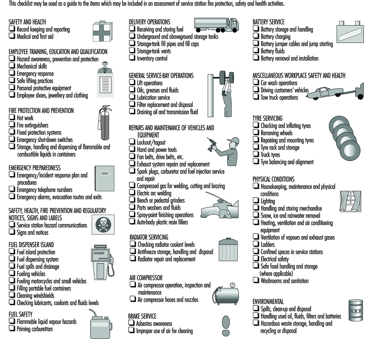
Robberies are a major safety hazard in service stations. Appropriate precautions and training are discussed in the accompanying box and elsewhere in this Encyclopaedia.
Health
Employees should be aware of health hazards associated with working in service stations, such as the following:
Carbon monoxide. Internal combustion engine exhaust gases contain carbon monoxide, a highly toxic, odourless and colourless gas. Employees should be aware of the dangers of exposure to carbon monoxide, particularly when vehicles are inside service bays, garages or car washes with their engines running. Vehicle exhaust gases should be piped outside through flexible hoses, and ventilation should be provided to assure an adequate supply of fresh air. Fuel oil appliances and heaters should be checked to assure that carbon monoxide is not vented to inside areas.
Toxicity of petroleum fuels. Employees who come in contact with gasoline, diesel fuel, heating oil or kerosene should be aware of the potential hazards of exposure and know how to handle these fuels safely. Inhaling sufficient concentrations of petroleum fuel vapours for extended periods of time may result in mild intoxication, anaesthesia or more serious conditions. Short exposure to high concentrations will cause dizziness, headaches and nausea, and irritate the eyes, nose and throat. Gasoline, solvents or fuel oils should never be siphoned from containers or tanks by mouth, since the toxicity of low viscosity liquid hydrocarbons aspired directly into the lungs is 200 times greater than if they are ingested. Aspiration into the lungs may cause pneumonia with extensive pulmonary oedema and haemorrhage, leading to serious injury or death. Vomiting should not be induced. Immediate medical assistance should be sought.
Benzene. Service station employees should be aware of the potential hazards of benzene, which is found in gasoline, and avoid inhaling gasoline vapours. Although gasoline contains benzene, low-level exposure to gasoline vapours is unlikely to cause cancer. Numerous scientific studies have shown that service station employees are not exposed to excessive levels of benzene during the course of their normal work activities; however, there is always the possibility that overexposure could occur.
Dermatitis hazards. Employees who handle and come into contact with petroleum products as part of their jobs should be aware of the hazards of dermatitis and other skin disorders and the personal hygiene and personal protective measures needed to control exposure. If eye contact with gasoline, lubricants or antifreeze occurs, the eyes should be flushed with clean, lukewarm potable water, and medical assistance should be provided.
Lubricants, used motor oil and automotive chemicals. Employees who change oil and other motor vehicle fluids, including antifreeze, should be aware of the hazards and know how to minimize exposure to products such as gasoline in used motor oil, glycol in antifreeze and other contaminants in transmission fluids and gear lubricants by the use of PPE and good hygiene practices. If high-pressure lubricating guns are discharged against an employee’s body, the affected area should be examined immediately to see if petroleum products have penetrated the skin. These injuries cause little pain or bleeding, but involve almost instant separation of the skin tissues and possible deeper damage, which should receive immediate medical attention. The attending physician should be informed of the cause and the product involved in the injury.
Welding. Welding, besides being a fire hazard, can involve exposure to lead pigments from welding on car exteriors, as well as metal fumes and welding gases. Local exhaust ventilation or respiratory protection is needed.
Spray painting and auto body fillers. Spray painting can involve exposure to solvent vapours and pigment particulates (e.g., lead chromate). Auto body fillers often are epoxy or polyester resins and can involve skin and respiratory hazards. Drive-in spray booths for spray painting, local exhaust ventilation and skin and eye protection are recommended while using auto body fillers.
Storage batteries. Batteries contain corrosive electrolyte solutions of sulphuric acid that can cause burns and other injuries to the eyes or skin. Exposure to battery solution should be minimized by the use of PPE, including rubber gloves and eye protection. Employees should immediately flush electrolyte solution from the eyes or skin with clean potable water or eye wash fluid for at least 15 minutes and seek immediate medical attention. Employees should thoroughly wash their hands after servicing batteries and keep their hands away from the face and eyes. Employees should be aware that overcharging batteries can create explosive and toxic quantities of hydrogen gas. Because of the potential harmful effects of exposure to lead, used storage batteries should be properly disposed of or recycled in accordance with government regulations or company policies.
Asbestos. Employees who check and service brakes should be aware of the hazards of asbestos, know how to recognize whether brake shoes contain asbestos and take appropriate protective measures to reduce exposure and contain waste for proper disposal (see figure 2).
Figure 2. Portable enclosure for preventing exposure to asbestos dust from brake drums It is equipped with an enclosed compressed-air gun with a cotton sleeve and is connected to a HEPA vacuum cleaner.
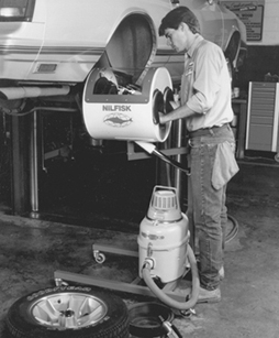
Courtesy of Nilfisk of America, Inc.
Personal protective equipment (PPE)
Injuries to employees may occur from contact with automotive fuels, solvents and chemicals or from chemical burns caused by exposure to battery acids or caustic solutions. Service station employees should be familiar with the need to use and wear PPE such as the following:
- Work shoes with oil- and slip-resistant soles should be worn for general work in service stations, and approved protective-toe safety shoes with oil/slip-resistant soles should be worn where there is a danger of foot injuries due to rolling or falling objects or equipment.
- Safety goggles and respiratory protection should be used for protection against exposures to chemicals, dust or steam, such as when painting or working around batteries and radiators. Industrial safety glasses or face shields with goggles should be worn when the potential exists for exposure to impact materials, such as working with grinders or wire buffers, repairing or mounting tyres, or replacing exhaust systems. Welding glasses should be worn when cutting or welding to prevent flash burns and injuries from particles.
- Impervious gloves, aprons, footwear, face shields and chemical goggles should be worn when handling automotive chemicals and solvents, battery acid and caustic solutions and when cleaning up chemical or fuel spills. Leather work gloves should be worn when handling sharp objects such as broken glass, motor vehicle parts or tyre rims and while emptying trash cans.
- Head protection may be needed when working beneath vehicles in pits or changing overhead signage or lights and in other areas where a potential exists for injury to the head.
- Employees working on vehicles should not wear rings, wristwatches, bracelets or long chains, since the jewellery may contact the vehicle’s moving parts or electrical system and cause injury.
To prevent fires, dermatitis or chemical burns to the skin, clothing that is soaked with gasoline, antifreeze or oil should be immediately removed in an area or room with good ventilation and where no sources of ignition, such as electric heaters, engines, cigarettes, lighters or electric hand dryers, are present. The affected areas of the skin should then be thoroughly washed with soap and warm water to remove all traces of contamination. Clothing should be air dried outside or in well-ventilated areas away from sources of ignition before laundering to minimize contamination of wastewater systems.
Service Station Environmental Issues
Storage tank inventory control
Service stations should maintain and reconcile accurate inventory records on all gasoline and fuel oil storage tanks on a regular basis to control losses. Manual stick gauging may be used to provide a check of the integrity of underground storage tanks and connecting pipes. Where automatic gauging or leak detection equipment is installed, its accuracy should be verified regularly by manual stick gauging. Any storage tank or system suspected of leaking should be investigated, and if leakage is detected, the tank should be made safe or emptied and repaired, removed or replaced. Service station employees should be aware that leaking gasoline can travel long distances underground, contaminate water supplies, enter sewer and drainage systems and cause fires and explosions.
Handling and disposal of waste materials
Waste lubricants and automotive chemicals, used motor oil and solvents, spilled gasoline and fuel oil and glycol-type antifreeze solutions should be drained into approved, properly labelled tanks or containers and stored until disposed of or recycled in accordance with government regulations and company policies.
Because engines with worn cylinders or other defects may allow small amounts of gasoline to enter their crankcases, precautions are needed to prevent vapours which could be released from tanks and containers with crankcase drainings from reaching sources of ignition.
Used oil filters and transmission fluid filters should be drained of oil prior to disposal. Used fuel filters which have been removed from vehicles or fuel dispenser pumps should be drained into approved containers and stored in well-ventilated locations away from sources of ignition until dry before disposal.
Used battery-electrolyte containers should be thoroughly rinsed with water before discarding or recycling. Used batteries contain lead and should be properly disposed of or recycled.
Cleaning large spills may require special training and PPE. Recovered spilled fuel may be returned to the terminal or bulk plant or otherwise disposed of according to government regulations or company policy. Lubricants, used oil, grease, antifreeze, spilled fuel and other materials should not be swept, washed or flushed into floor drains, sinks, toilets, sewers, sumps or other drains or the street. Accumulated grease and oil should be removed from floor drains and sumps to prevent these materials from flowing into sewers. Asbestos dust and used asbestos brake linings should be handled and disposed of according to government regulations and company policies. Employees should be aware of the environmental impact and potential health, safety and fire hazards of these wastes.
Ergonomics of Bus Driving
Bus driving is characterized by psychological and physical stresses. Most severe are the stresses of traffic in big cities, because of the heavy traffic and frequent stops. In most transit companies, the drivers must, in addition to driving responsibilities, handle tasks such as selling tickets, observing passenger loading and unloading and providing information to passengers.
Psychological stresses result from the responsibility for the safe transport of passengers, scant opportunity to communicate with colleagues and the time pressure of holding to a fixed schedule. Rotating shift work is also psychologically and physically stressful. Ergonomic shortcomings in the driver’s workstation increase physical stresses.
Numerous studies of the activity of bus drivers have shown that the individual stresses are not great enough to cause an immediate health hazard. But the sum of the stresses and the resulting strain leads to bus drivers having more frequent health problems than other workers. Especially significant are diseases of the stomach and digestive tract, of the motor system (especially the spine) and of the cardiovascular system. This results in drivers often not reaching retirement age, but rather having to quit driving early for health reasons (Beiler and Tränkle 1993; Giesser-Weigt and Schmidt 1989; Haas, Petry and Schühlein 1989; Meifort, Reiners and Schuh 1983; Reimann 1981).
In order to achieve more effective occupational safety in the field of commercial driving, technical as well as organizational measures are necessary. An important work practice is the arranging of shift schedules so that the stress on the drivers is minimized and their personal desires are also taken into account to the extent possible. Informing the personnel of and motivating them to health-conscious conduct (e.g., proper diet, adequate movement within and outside of the workstation) can play an important role in promoting health. An especially necessary technical measure is the ergonomically optimal design of the driver’s workstation. In the past, the requirements of the driver’s workstation were considered only after other requirements, such as design of the passenger area. Ergonomic design of the driver’s workstation is a necessary component of driver safety and health protection. In recent years, research projects on, among other things, the ergonomically optimal driver’s workstation were conducted in Canada, Sweden, Germany and the Netherlands (Canadian Urban Transit Association 1992; Peters et al. 1992; Wallentowitz et al. 1996; Streekvervoer Nederland 1991). The results of the interdisciplinary project in Germany resulted in a new, standardized driver’s workstation (Verband Deutscher Verkehrsunternehmen 1996).
The driver’s workstation in buses is normally designed in the form of a half-open cabin. The measurements of the driver’s cabin and the adjustments that can be made to the seat and steering wheel must fall within a range that is applicable to all drivers. For central Europe, this means a body-size range of 1.58 to 2.00 m. Special proportions, such as being overweight and having long or short limbs, should also be taken into account in the design.
The adjustability and the ways of adjusting the driver’s seat and steering wheel should be coordinated so that all drivers within the design range can find positions for their arms and legs that are comfortable and ergonomically healthy. For this purpose, the optimal seat placement has a back incline about 20°, which is further from the vertical than has previously been the norm in commercial vehicles. Furthermore, the instrument panel should also be adjustable for optimal access to adjustment levers and for good visibility of the instruments. This can be coordinated with the steering wheel adjustment. Using a smaller steering wheel also improves spatial relations. The steering wheel diameter now in general use apparently comes from a time when power steering was not common in buses. See figure 1.
Figure 1. Ergonomically optimized and unified driver's workstation for busses in Germany.
Courtesy of Erobus GmbH, Mannheim, Germany
The instrument panel with the controls can be adjusted in coordination with the steering wheel.
Since stumbling and falling are the most common causes of workplace accidents among drivers, particular attention should be paid to the design of the entrance to the driver’s workstation. Anything that can be stumbled on should be avoided. Steps in the entrance area must be of equal height and have adequate step depth.
The driver’s seat should have a total of five adjustments: seat length and height settings, seat back angle, seat bottom angle and seat depth. Adjustable lumbar support is strongly advised. To the extent that it is not already legally required, equipping the driver’s seat with a three-point seat-belt and head rest are recommended. Since experience shows that manually adjusting to the ergonomically right position is time-consuming, in the future some way of electronically storing the adjustment functions listed in table 1 should be used, allowing for quickly and easily refinding the individual seating adjustment (e.g., by entering it onto an electronic card).
Table 1. Bus driver seat measurements and seat adjustment ranges.
|
Component |
Measurement/ |
Standard value |
Adjustment range |
Memorized |
|
Entire seat |
Horizontal |
— |
≥ 200 |
Yes |
|
Vertical |
— |
≥ 100 |
Yes |
|
|
Seat surface |
Seat surface depth |
— |
390–450 |
Yes |
|
Seat surface width (total) |
Min. 495 |
— |
— |
|
|
Seat surface width (flat part, in pelvic area) |
430 |
— |
— |
|
|
Side upholstering in pelvic area (crosswise) |
40–70 |
— |
— |
|
|
Depth of seat recess |
10–20 |
— |
— |
|
|
Seat surface slope |
— |
0–10° (rising toward front) |
Yes |
|
|
Seatback |
Seatback height |
|||
|
Min. height |
495 |
— |
— |
|
|
Max. height |
640 |
— |
— |
|
|
Seatback width (total)* |
Min. 475 |
— |
— |
|
|
Seatback width (flat part) |
||||
|
—lumbar area (lower) |
340 |
— |
— |
|
|
—shoulder area (upper) |
385 |
— |
— |
|
|
Seatback |
Side upholstering* (side depth) |
|||
|
—lumbar area (lower) |
50 |
— |
— |
|
|
—shoulder area (upper) |
25 |
— |
— |
|
|
Seatback slope (to vertical) |
— |
0°–25° |
Yes |
|
|
Headrest |
Height of headrest upper edge above seat surface |
— |
Min. 840 |
— |
|
Height of headrest itself |
Min. 120 |
— |
— |
|
|
Width of headrest |
Min. 250 |
— |
— |
|
|
Lumbar pad |
Forward arch of lumbar support from lumbar surface |
— |
10–50 |
— |
|
Height of lumbar support lower edge over seat surface |
— |
180–250 |
— |
– Not applicable
* The width of the lower part of the backrest should correspond approximately to the width of the seat surface and grow narrower as it goes up.
** The side upholstering of the seat surface applies only to the recess area.
Stress through whole-body vibrations in the driver’s workstation is low in modern buses compared to other commercial vehicles, and it falls well below the international standards. Experience shows that driver’s seats in buses are often not optimally adjusted to the vehicle’s actual vibration. An optimal adaptation is advised to avoid certain frequency ranges causing an increase in whole-body vibration on the driver, which can interfere with productivity.
Noise levels that are a hazard to hearing are not anticipated in the bus driver’s workstation. High-frequency noise can be irritating and should be eliminated because it could interfere with the drivers’ concentration.
All adjustment and service components in the driver’s workstation should be arranged for comfortable access. A large number of adjustment components are often required due to the amount of equipment added to the vehicle. For this reason, switches should be grouped and consolidated according to use. Frequently used service components such as door openers, bus stop brakes and windshield wipers should be placed in the main access area. Less frequently used switches can be located outside the main access area (e.g., on a side console).
Analyses of visual movements have shown that driving the vehicle in traffic and observing the loading and unloading of passengers at the stops is a serious burden on the driver’s attention. Thus, the information conveyed by instruments and indicator lights in the vehicle should be limited to those absolutely necessary. Vehicle computerized electronics offer the possibility of eliminating numerous instruments and indicator lights, and instead installing a liquid crystal display (LCD) in a central location to convey information, as shown in the instrument panel in figure 2 and figure 3.
Figure 2. View of an instrument panel.

Courtesy of Erobus GmbH, Mannheim, Germany
With the exception of the speedometer and a few legally required indicator lights, the functions of the instrument and indicator displays have been assumed by a central LCD display.
Figure 3. Illustration of an instrument panel with legend.
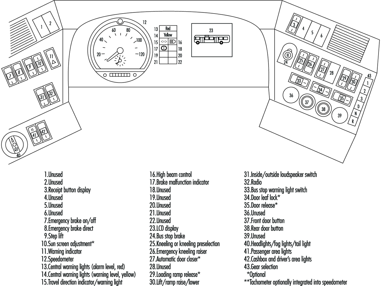
With the proper computer software, the display will show only a selection of information that is needed for the particular situation. In the case of malfunction, a description of the problem and brief instructions in clear text, rather than in difficult-to- understand pictograms, can provide the driver with important assistance. A hierarchy of malfunction notifications can also be established (e.g., “advisory” for less significant malfunctions, “alarm” when the vehicle must be stopped immediately).
Heating systems in buses often heat the interior with warm air only. For real comfort, however, a higher proportion of radiant heat is desirable (e.g., by heating the side walls, whose surface temperature often lies significantly below the interior air temperature). This, for example, can be achieved by circulating warm air through perforated wall surfaces, which thereby will also have the right temperature. Large window surfaces are used in the driver’s area in buses to improve visibility and also for appearance. These can lead to a significant warming of the inside by sun rays. The use of air conditioning is thus advisable.
The air quality of the driver’s cabin depends heavily on the quality of the outside air. Depending on the traffic, high concentrations of harmful substances, such as carbon monoxide and diesel motor emissions, can briefly occur. Providing fresh air from less-used areas, such as the roof instead of the vehicle front, lessens the problem significantly. Fine-particle filters should also be used.
In most transit companies, an important part of the driving personnel’s activity consists of selling tickets, operating devices to provide information to passengers and communicating with the company. Until now, separate devices, located in the available work space and often hard for the driver to reach, have been used for these activities. An integrated design should be sought from the start that arranges the devices in an ergonomically convenient manner in the driver’s area, especially the input keys and display panels.
Finally, the assessment of the driver’s area by the drivers, whose personal interests should be taken into account, is of great importance. Supposedly minor details, such as placement of the driver’s bag or storage lockers for personal effects, are important for driver satisfaction.
Truck and Bus Driving
Transport by road includes the movement of people, livestock and freight of all kinds. Freight and livestock generally move in some form of truck, although buses often carry packages and passenger baggage and may transport fowl and small animals. People generally move by bus on the road, although in many areas trucks of various kinds serve this function.
Truck (lorry) drivers may operate several different types of vehicles, including, for example, semi-trailers, tanker trucks, dump trucks, double and triple trailer combinations, mobile cranes, delivery trucks and panel or pickup vehicles. Legal gross vehicle weights (which vary by jurisdiction) range from 2,000 kg to over 80,000 kg. Truck cargo may include any imaginable item—for example, small and large packages, machinery, rock and sand, steel, lumber, flammable liquids, compressed gases, explosives, radioactive materials, corrosive or reactive chemicals, cryogenic liquids, food products, frozen foods, bulk grain, sheep and cattle.
In addition to driving the vehicle, truck drivers are responsible for inspecting the vehicle prior to use, checking shipping papers, verifying that proper placards and markings are in place and maintaining a log book. Drivers may also be responsible for servicing and repairing the vehicle, loading and unloading cargo (either by hand or using a fork truck, crane or other equipment) and collecting money received for goods delivered. In the event of an accident, the driver is responsible for securing the cargo and summoning assistance. If the incident involves hazardous materials, the driver may attempt, even without proper training or necessary equipment, to control spills, stop leaks or put out a fire.
Bus drivers may carry a few people in a small van or operate medium and large buses carrying 100 or more passengers. They are responsible for boarding and discharging passengers safely, providing information and possibly collecting fares and maintaining order. Bus drivers may also be responsible for servicing and repairing the bus and loading and unloading cargo and baggage.
Motor vehicle accidents are one of the most serious hazards facing both truck and bus drivers. This hazard is aggravated if the vehicle is not properly maintained, especially if the tyres are worn or the brake system is faulty. Driver fatigue caused by a long or irregular schedules, or by other stress, increases the likelihood of accidents. Excessive speed and hauling excessive weight add to the risk, as do heavy traffic and adverse weather conditions which impair traction or visibility. An accident involving hazardous materials may cause additional injury (toxic exposure, burns and so on) to the driver or passengers and may affect a wide area surrounding the accident.
Drivers face a variety of ergonomic hazards. The most obvious are back and other injuries caused by lifting excessive weight or using improper lifting technique. The use of back belts is quite common, although their efficacy has been questioned, and their use may create a false sense of security. The necessity of loading and unloading cargo at locations where fork-lift trucks, cranes or even dollies are not available and the great variety of package weights and configurations add to the risk of lifting injuries.
Driver’s seats are often poorly designed and cannot be adjusted to provide proper support and long-term comfort, resulting in back problems or other musculoskeletal damage. Drivers may experience damage to the shoulder caused by vibration as the arm may rest for long periods in a somewhat raised position on the window opening. Whole-body vibration can cause damage to the kidneys and back. Ergonomic injury may also result from repetitive use of poorly placed vehicle controls or fare box keypads.
Drivers are at risk of industrial hearing loss caused by long-term exposure to loud engine noises. Poor maintenance, faulty mufflers and inadequate cab insulation aggravate this hazard. Hearing loss may be more pronounced in the ear adjacent to the driver’s window.
Drivers, especially long-haul truck drivers, often work excessive hours without adequate rest. The International Labour Organization (ILO) Hours of Work and Rest Periods (Road Transport) Convention, 1979 (No. 153), requires a break after 4 hours of driving, limits total driving time to 9 hours per day and 48 hours per week and requires at least 10 hours of rest in each 24-hour period. Most nations also have laws which govern driving times and rest periods and require drivers to maintain logbooks indicating hours worked and rest periods taken. However, management expectations and economic necessity, as well as certain terms of remuneration, such as pay per load or the lack of pay for an empty return trip, put strong pressure on the driver to operate for excessive hours and to make bogus log entries. Long hours cause psychological stress, aggravate ergonomic problems, contribute to accidents (including accidents caused by falling asleep at the wheel) and may cause the driver to use artificial, addictive stimulants.
In addition to ergonomic conditions, long work hours, noise and economic anxiety, drivers experience psychological and physiological stress and fatigue caused by adverse traffic conditions, poor road surfaces, bad weather, night driving, the fear of assault and robbery, concern about faulty equipment and continuous intense concentration.
Truck drivers are potentially exposed to any chemical, radioactive or biological hazard associated with their load. Leaking containers, faulty valves on tanks and emissions during loading or unloading may cause worker exposures to toxic chemicals. Improper packaging, inadequate shielding or improper placement of radioactive cargo may allow radiation exposure. Workers transporting livestock may be infected with animal-borne infections such as brucellosis. Bus drivers are exposed to infectious diseases of their passengers. Drivers are also exposed to fuel vapours and engine exhaust, especially if there are fuel-line or exhaust system leaks or if the driver makes repairs or handles freight while the engine is running.
In the event of an accident involving hazardous materials, the driver may experience acute chemical or radiation exposures or may be injured by a fire, explosion or chemical reaction. Drivers generally lack the training or equipment to deal with hazardous materials incidents. Their responsibility should be limited to protecting themselves and summoning emergency responders. The driver faces additional risks in attempting emergency response actions for which he or she is not properly trained and adequately equipped.
The driver may be injured in the course of making mechanical repairs to the vehicle. A driver could be struck by another vehicle while working on a truck or bus alongside the road. Wheels with split rims pose a special injury hazard. Improvised or inadequate jacks may cause a crushing injury.
Truck drivers face the risk of assault and robbery, especially if the vehicle carries a valuable cargo or if the driver is responsible for collecting money for goods delivered. Bus drivers are at risk of fare box robberies and abuse or assault by impatient or inebriated passengers.
Many aspects of a driver’s life may contribute to poor health. Because they work long hours and need to eat on the road, drivers often suffer from poor nutrition. Stress and peer pressure may lead to drug and alcohol use. Using the services of prostitutes increases the risk of AIDS and other sexually transmitted diseases. The drivers appear to be one of the main vectors for carrying AIDS in some countries.
The risks described above are all preventable, or at least controllable. As with most safety and health issues, what is needed is a combination of adequate remuneration, worker training, a strong union contract and strict adherence to applicable standards on the part of management. If drivers receive adequate pay for their work, based on proper work schedules, there is less incentive to speed, work excessive hours, drive unsafe vehicles, carry overweight loads, take drugs or make bogus log entries. Management must require drivers to comply with all safety laws, including keeping an honest logbook.
If management invests in well-made vehicles and assures their regular inspection, maintenance and servicing, breakdowns and accidents can be greatly reduced. Ergonomic injury can be reduced if management is willing to pay for the well-designed cabs, fully adjustable driver’s seats and good vehicle control arrangements that are now available. Proper maintenance, especially of exhaust systems, will reduce noise exposure.
Toxic exposures can be reduced if management assures compliance with packaging, labelling, loading and placarding standards for hazardous materials. Measures which reduce vehicular accidents also reduce the risk of a hazardous materials incident.
Drivers must be given time to thoroughly inspect the vehicle prior to use and must not face any penalty or disincentive for refusing to operate a vehicle that is not functioning properly. Drivers must also receive adequate driver training, vehicle inspection training, hazard recognition training and first-responder training.
If drivers are responsible for loading and unloading, they must receive training in proper lifting technique and be provided with hand-trucks, fork-lifts, cranes or other equipment necessary to handle goods without excessive strain. If drivers are expected to make repairs to vehicles, they must be provided with the correct tools and proper training. Adequate security measures must be taken to protect drivers who transport valuables or handle passenger fares or money received for goods delivered. Bus drivers should have proper supplies for dealing with body fluids from sick or injured passengers.
Drivers must receive medical services both to assure their fitness for work and to maintain their health. Medical surveillance must be provided for drivers who handle hazardous materials or are involved in an incident with exposure to blood-borne pathogens or hazardous materials . Both management and drivers must comply with standards governing the evaluation of medical fitness.
Health Effects and Disease Patterns
The health and safety problems in the forestry and lumber industries are covered elsewhere in this Encyclopaedia. This article will deal with wood as it arrives from the mill and is used in carpentry and the making of furniture and other articles. These activities are predominantly performed in small enterprises. Many workers in these industries are individual contractors and, therefore, not listed as employees, and large numbers of individuals are exposed in do-it-yourself projects and in-home workshops. This means that many of the workers involved are inadequately trained and are supervised poorly or not at all, while proper safeguards and protective equipment are often lacking.
Ahman and colleagues (1995a, 1995b, 1996) call attention to the exposure of teachers of industrial arts and woodworking in Sweden. In contrast to unexposed controls, these teachers had notable (but mainly reversible) nasal effects and complaints that increased with the number of classes from the beginning of the week and receded over the weekends, even though the dust concentrations were below the Swedish threshold limit of 2 mg/m3. In several establishments in the Netherlands, dust levels regularly exceeded that limit, and during sanding operations in a furniture factory, almost all exposures were over the local threshold limit of 5 mg/m3 (Scheeper, Kromhout and Boleij 1995).
Accidental Injuries
The most common health problem in the wood and woodworking industries is accidental injuries. These are more frequent among younger, inexperienced workers, and, for the most part, they are relatively minor. On occasion, however, they may involve long-term impairment or loss of an extremity. They include: splinters, which may become infected, and lacerations, gouges and amputations resulting from improperly used or inadequately guarded woodworking machinery (Ma, Wang and Chou 1991); sprains and strains from injudicious lifting or working in an awkward position (Nestor, Bobick and Pizatella 1990); repetitive motion injuries involving the hand or shoulder; and eye injuries. Many if not most of these can be prevented by proper training, the judicious application of machine guards and restraints and the use of personal protective equipment such as gloves and safety glasses. When they occur, prompt removal of splinters and prevention of infection by expeditious cleansing and first aid treatment of wounds will minimize disability.
Wood Dust
Wood dust exposure occurs whenever wood is sawed, chipped, planed, routed or sanded. The effects vary with the intensity and duration of the exposure and the size of the particles. Particles in the eyes may cause irritation, and wood dust gathering in skin folds may be aggravated by perspiration and chemicals and lead to irritation and infection. These effects may be reduced by vacuum removal of the dust, protective masks and clothing and good personal hygiene practices.
Nasopharyngeal and respiratory passages
Wood dust in the nasal passages may diminish mucociliary clearance and impair olfactory sensitivity (Andersen, Solgaard and Andersen 1976; Ahman et al. 1996). These may lead to irritation, frequent sneezing, nosebleeds and infection of the sinuses (Imbus 1994).
Exposures in a furniture factory (Whitehead, Ashikaga and Vacek 1981) and in sawmill workers (Hessel et al. 1995) were shown to be accompanied by decreases in both 1-second forced expiratory volume (FEV1) and forced vital capacity (FVC), adjusted for age, height and smoking. These were accompanied by significant increases in shortness of breath and wheeze with chest tightness and the occurrence of bronchitis and asthma. There is, however, no convincing evidence of other lung disease due to wood dust exposures (Imbus 1994). In a 6-year prospective follow-up study of approximately 350,000 males in the United States, the 11,541 individuals who reported having been employed in wood-related occupations had a lower relative risk of mortality due to non-malignant respiratory disease than those who did not report exposure to wood dust (Demers et al. 1996).
Allergy and Asthma
Some woods, notably teak, mansonia and radiata pine, contain chemicals that are irritants (see table 1 for an extended list of wood species, their geographic origins, and their health effects). Some species may cause allergic contact dermatitis (e.g., Douglas fir, western red cedar, poplar, rosewood, teak, African mahogany and other “exotic” woods). Western red cedar, rosewood, mahogany and other exotic woods have been shown to cause asthma (Imbus 1994).
Cancer
An unusually high incidence of nasal cancer has been described among woodworkers in Australia, Canada, Denmark, Finland, France, Italy, the Netherlands, the United Kingdom and the United States (Imbus 1994). A recent pooled re-analysis of 12 case-control cohort studies conducted in seven countries confirmed a high risk of nasopharyngeal cancer among woodworkers (Demers et al. 1995). The cause of these excesses of nasal cancer is not known, but, according to recent reports from the United Kingdom and the United States, the risk of nasal cancer among furniture workers has declined since the Second World War, presumably reflecting changes in the manufacturing process (Imbus 1994). No excess risk of sino-nasal cancer was found among the 45,399 men exposed to wood dust included among the 362,823 men enrolled in the American Cancer Society’s 6-year Cancer Prevention Study, but, the researchers note, the number of cases was small. They did, however, find an especially high increase in lung cancer mortality among woodworkers who also reported exposure to asbestos or formaldehyde, and suggested that exposure to these known carcinogens was responsible for the observed increased risk (Stellman et al., in press).
Chemical Exposures
Wood may contain biological contaminants. Moulds and fungi, which often grow on the bark of trees, may cause allergic reactions. Inhalation of fungal spores found on maple, redwood and cork trees has been shown to cause maple bark disease, sequoiosis and suberosis (Imbus 1994).
Wood often contains exogenous chemicals applied in the course of its processing. These include adhesives, solvents, resin binders, insecticides and fungicides, waterproofing compounds, paints and pigments, lacquers and varnishes. Many of these are volatile and may be emitted when the wood is treated, heated or incinerated; they are also conveyed as elements in wood dust. The most important of these include: toluene, methanol, xylene, methyl ethyl ketone, n-butyl alcohol, 1, 1,1-trichlorethane and dichloromethane (EPA 1995).
Conclusion
Health hazards of the wood and woodworking industries may be controlled by installation of engineering controls (e.g., proper placement and guarding of power machinery, ventilation systems to control wood dust and chemical emissions) and personal protective equipment (e.g., gloves, safety glasses, respirators), coupled with periodic inspections to ensure that these are properly maintained and used. Perhaps most important is appropriate education and training of the workers and their supervisors.
Table 1. Poisonous, allergenic and biologically active wood varieties
| Scientific names | Selected commercial names | Family | Health Impairment |
| Abies alba Mill (A. pectinata D.C.) | Silver fir | Pinaceae | Dermatitis; conjunctivitis-rhinitis; asthma |
| Acacia spp. A. harpophylla F. Muell. A. melanoxylon R. Br. A. seyal Del. A. shirley Maiden |
Australian blackwood | Mimosaceae | Dermatitis; conjunctivitis-rhinitis; asthma; toxic effects |
| Acer spp. A. platanoides L. |
Maple | Aceraceae | Dermatitis |
| Afrormosia elata Harms. (Pericopsis elata Van Meeuwen) |
Afrormosia, kokrodua, asamala, obang, oleo pardo, bohele, mohole | Papilionaceae | Dermatitis; conjunctivitis-rhinitis; asthma |
| Afzelia africana Smith A. bijuga A. Chev. (Intsia bijuga A. Cunn.) A. palembanica Bak. (Intsia palembanica Bak.) |
Doussié, afzelia, aligua, apa, chanfuta, lingue merbau, intsia, hintsy | Caesalpinaceae | Dermatitis; conjunctivitis-rhinitis; asthma |
| Agonandra brasiliensis Miers | Pao, marfim, granadillo | Olacaceae | Dermatitis |
| Ailanthus altissima Mill | Chinese sumac | Simaroubaceae | Dermatitis |
| Albizzia falcata Backer A. ferruginea Benth. A. lebbek Benth A. toona F.M. Bail |
Iatandza Kokko, siris |
Mimosaceae | Dermatitis; conjunctivitis-rhinitis; asthma; toxic effects |
| Alnus spp. A. glutinosa Gaertn. |
Common alder Black alder |
Betulaceae | Dermatitis; conjunctivitis-rhinitis; asthma |
| Amyris spp. A. balsamifera L. A. toxifera Willd. |
Venezuelan or West Indian sandalwood | Rutaceae | Dermatitis; toxic effects |
| Anacardium occidentale L. A. excelsum Skels. |
Cashew | Anacardiaceae | Dermatitis |
| Andira araroba Aguiar. (Vataireopsis araroba Ducke) A. coriacea Pulle A. inermis H.B.K. |
Red cabbage tree Partridge wood | Papilionaceae | Dermatitis; conjunctivitis-rhinitis; asthma |
| Aningeria spp. A. robusta Aubr. and Pell. A. altissima Aubr. and Pell. Antiaris africana Engl. A. welwitschi Engl. |
Aningeria Antiaris, ako, chen chen | Sapotaceae Moraceae | Conjunctivitis-rhinitis; asthma Toxic effects |
| Apuleia molaris spruce (A. leiocarpa MacBride) (A. ferrea Mart.) |
Redwood | Caesalpinaceae | Dermatitis; toxic effects |
| Araucaria angustifolia O. Ktze A. brasiliana A. Rich. |
Parana pine, araucaria | Araucariaceae | Toxic effects |
| Aspidosperma spp. A. peroba Fr. All. A. vargasii A. DC. |
Red peroba Pau marfim, pau amarello, pequia marfim, guatambu, amarilla, pequia | Apocynaceae | Dermatitis; conjunctivitis- rhinitis; asthma; toxic effects |
| Astrocaryum spp. | Palm | Palmaceae | Dermatitis; toxic effects |
| Aucoumea klaineana Pierre | Gabon mahogany | Burseraceae | Dermatitis; conjunctivitis-rhinitis; asthma; allergic extrinsic alveolitis |
| Autranella congolensis A. Chev. (Mimusops congolensis De Wild.) |
Mukulungu, autracon, elang, bouanga, kulungu | Sapotaceae | Dermatitis |
| Bactris spp. (Astrocaryum spp.) | Palm | Palmaceae | Dermatitis; toxic effects |
| Balfourodendron riedelianum Engl. | Guatambu, gutambu blanco | Rutaceae | Dermatitis |
| Batesia floribunda Benth. | Acapu rana | Caesalpinaceae | Toxic effects |
| Berberis vulgaris L. | Barberry | Berberidaceae | Toxic effects |
| Betula spp. B. alba L. (B. pendula Roth.) |
Birch | Betulaceae | Dermatitis |
| Blepharocarva involucrigera F. Muell. | Rosebutternut | Anacardiaceae | Dermatitis; conjunctivitis-rhinitis; asthma |
| Bombax brevicuspe Sprague B. chevalieri Pell |
Kondroti, alone | Bombacaceae | Dermatitis |
| Bowdichia spp. B. nitida Benth. B. guianensis Ducke (Diplotropis guianensis Benth.) (Diplotropis purpurea Amsh.) |
Black sucupira | Papilionaceae | Dermatitis |
| Brachylaena hutchinsii Hutch. | Muhuhu | Compositae | Dermatitis |
| Breonia spp. | Molompangady | Rubiaceae | Dermatitis |
| Brosimum spp. B. guianense Hub. (Piratinera guianensis Aubl.) |
Snakewood, letterwood, tigerwood | Moraceae | Dermatitis; conjunctivitis-rhinitis; asthma; toxic effects |
| Brya ebenus DC. (Amerimnum ebenus Sw.) Brya buxifolia Urb. |
Brown ebony, green ebony, Jamaican ebony, tropical American ebony | Papilionaceae | Dermatitis |
| Buxus sempervirens L. B. macowani Oliv. |
European boxwood, East London b., Cape b. | Buxaceae | Dermatitis; conjunctivitis-rhinitis; asthma; toxic effects |
| Caesalpinia echinata Lam. (Guilandina echinata Spreng.) | Brasilwood | Caesalpinaceae | Dermatitis; toxic effects |
| Callitris columellaris F. Muell. | White cypress pine | Cupressaceae | Dermatitis; conjunctivitis-rhinitis; asthma |
| Calophyllum spp. C. brasiliense Camb. |
Santa maria, jacareuba, kurahura, galba | Guttiferae | Dermatitis; toxic effects |
| Campsiandra laurifolia Benth. | Acapu rana | Caesalpinaceae | Toxic effects |
| Carpinus betulus | Hornbeam | Betulaceae | Dermatitis |
| Cassia siamea Lamk. | Tagayasan, muong ten, djohar | Caesalpinaceae | Dermatitis; conjunctivitis-rhinitis; asthma |
| Castanea dentata Borkh C. sativa Mill. C. pumila Mill. |
Chestnut, sweet chestnut | Fagaceae | Dermatitis; conjunctivitis-rhinitis; asthma |
| Castanospermum australe A. Cunn. | Black bean, Australian or Moreton Bay chestnut | Papilionaceae | Dermatitis |
| Cedrela spp. (Toona spp.) | Red cedar, Australian cedar | Meliaceae | Dermatitis; conjunctivitis-rhinitis; asthma |
| Cedrus deodara (Roxb. ex. Lamb.) G. Don (C. libani Barrel. lc) |
Deodar | Pinaceae | Dermatitis; conjunctivitis-rhinitis; asthma |
| Celtis brieyi De Wild. C. cinnamomea Ldl. |
Diania Gurenda |
Ulmaceae | Dermatitis |
| Chlorophora excelsa Benth. and Hook I. C. regia A. Chev. C. tinctoria (L.) Daub. |
Iroko, gelbholz, yellowood, kambala, mvule, odum, moule, African teak, abang, tatajuba, fustic, mora | Moraceae | Dermatitis; conjunctivitis-rhinitis; asthma; allergic extrinsic alveolitis |
| Chloroxylon spp. C. swietenia A.DC. |
Ceylon satinwood | Rutaceae | Dermatitis; toxic effects |
| Chrysophyllum spp. | Najara | Sapotaceae | Dermatitis |
| Cinnamomum camphora Nees and Ebeim | Asian camphorwood, cinnamon | Lauraceae | Toxic effects |
| Cryptocarya pleurosperma White and Francis | Poison walnut | Lauraceae | Dermatitis; conjunctivitis-rhinitis; asthma; toxic effects |
| Dacrycarpus dacryoides (A. Rich.) de Laub. | New Zealand white pine | Podocarpaceae | Dermatitis; conjunctivitis-rhinitis; asthma |
| Dacrydium cupressinum Soland | Sempilor, rimu | Podocarpaceae | conjunctivitis-rhinitis; asthma |
| Dactylocladus stenostachys Oliv. | Jong kong, merebong, medang tabak | Melastomaceae | Toxic effects |
| Dalbergia spp. D. amerimnon Benth. D. granadillo Pitt. D. hypoleuca Standl. D. latifolia Roxb. D. melanoxylon Guill. and Perr. D. nigra Fr. All. D. oliveri Gamble D. retusa Hemsl. D. sissoo Roxb. D. stevensonii Standl. |
Ebony Red foxwood Indian rosewood, Bombay blackwood, African blackwood, pallisander, riopalissandro, Brasilian rosewood, jacaranda Burma rosewood Red foxwood Nagaed wood, Honduras rosewood |
Papilionaceae | Dermatitis; conjunctivitis-rhinitis; asthma; toxic effects |
| Dialium spp. D. dinklangeri Harms. |
Eyoum, eyum | Caesalpinaceae | Dermatitis; conjunctivitis-rhinitis; asthma |
| Diospyros spp. D. celebica Bakh. D. crassiflora Hiern D. ebenum Koenig |
Ebony, African ebony Macassar ebony, African ebony, Ceylon ebony | Ebenaceae | Dermatitis; conjunctivitis-rhinitis; asthma; toxic effects |
| Dipterocarpus spp. D. alatus Roxb. |
Keruing, gurjum, yang, keruing | Dipterocarpaceae | Dermatitis |
| Distemonanthus benthamianus Baill. | Movingui, ayan, anyaran, Nigerian satinwood | Caesalpinaceae | Dermatitis |
| Dysoxylum spp. D. fraseranum Benth. |
Mahogany, stavewood, red bean | Meliaceae | dermatitis; conjunctivitis-rhinitis; asthma; toxic effects |
| D. muelleri Benth. | Rose mahogany | ||
| Echirospermum balthazarii Fr. All. (Plathymenia reticulataBenth.) | Vinhatico | Mimosaceae | Dermatitis; conjunctivitis-rhinitis; asthma |
| Entandophragma spp. E. angolense C.D.C. E. candollei Harms. E. cylindricum Sprague E. utile Sprague |
Tiama Kosipo, omo Sapelli, sapele, aboudikro Sipo, utile, assié, kalungi, mufumbi |
Meliaceae | Dermatitis; allergic extrinsic alveolitis |
| Erythrophloeum guineense G. Don E. ivorense A. Chev. |
Tali, missanda, eloun, massanda, sasswood, erun, redwater tree | Caesalpinaceae | Dermatitis; conjunctivitis-rhinitis; asthma; toxic effects |
| Esenbeckia leiocarpa Engl. | Guaranta | Rutaceae | Dermatitis |
| Eucalyptus spp. E. delegatensis R.T. Back E. hemiphloia F. Muell. E. leucoxylon Maiden E. maculata Hook. E. marginata Donn ex Sm. E. microtheca F. Muell. E. obliqua L. Herit. E. regnans F. Muell. E. saligna Sm. |
Alpine ash Grey box Yellow gum Spotted gum Mountain ash |
Myrtaceae | Dermatitis; conjunctivitis-rhinitis; asthma |
| Euxylophora paraensis Hub. | Boxwood | Rutaceae | Dermatitis; conjunctivitis-rhinitis; asthma |
| Excoecaria africana M. Arg. (Spirostachys africana Sand) E. agallocha L. |
African sandalwood, tabootie, geor, aloewood, blind-your-eye | Euphorbiaceae | Dermatitis; conjunctivitis-rhinitis; asthma; toxic effects |
| Fagara spp. F. flava Krug and Urb. (Zanthoxylum flavum Vahl.) F. heitzii Aubr. and Pell. F. macrophylla Engl. |
Yellow sanders, West Indian satinwood, atlaswood, olon, bongo, mbanza | Rutaceae | Dermatitis; conjunctivitis-rhinitis; asthma; toxic effects |
| Fagus spp. (Nothofagus spp.) F. sylvatica L. |
Beech | Fagaceae | Dermatitis; conjunctivitis-rhinitis; asthma |
| Fitzroya cupressoides (Molina) Johnston (F. patagonica Hook. f.) |
Alerce | Cupressaceae | Dermatitis |
| Flindersia australis R. Br. F. brayleyana F. Muell. F. pimenteliana F. Muell. |
Australian teak, Queensland maple, maple Silkwood, Australian maple |
Rutaceae | Dermatitis |
| Fraxinus spp. F. excelsior L. |
Ash | Oleaceae | Dermatitis |
| Gluta spp. G. rhengas L. (Melanorrhoea spp.) M. curtisii Pierre M. laccifera wallichii Hook. |
Rengas, gluta Renga wood Rhengas |
Anacardiaceae | Dermatitis; toxic effects |
| Gonioma kamassi E. Mey. | Knysna boxwood, kamassi | Apocynaceae | Dermatitis; conjunctivitis-rhinitis; asthma; toxic effects |
| Gonystylus bancanus Baill. | Ramin, melawis, akenia | Gonystylaceae | Dermatitis; conjunctivitis-rhinitis; asthma; allergic extrinsic alveolitis |
| Gossweilerodendron balsamiferum (Verm.) Harms. | Nigerian cedar | Caesalpinaceae | Dermatitis; conjunctivitis-rhinitis; asthma |
| Grevillea robusta A. Cunn. | Silky oak | Proteaceae | Dermatitis |
| Guaiacum officinale L. | Gaiac, lignum vitae | Zygophyllaceae | Dermatitis; conjunctivitis-rhinitis; asthma |
| Guarea spp. G. cedrata Pell. G. laurentii De Wild. G. thompsonii Sprague |
Bossé Nigerian pearwood Cedar mahogany Scented guarea Black guarea |
Meliaceae | Dermatitis; conjunctivitis-rhinitis; asthma; toxic effects |
| Halfordia scleroxyla F. Muell. H. papuana Lauterb. |
Saffron-heart | Polygonaceae | Dermatitis; allergic extrinsic alveolitis |
| Hernandia spp. H. sonora L. (H. guianensis Aubl.) |
Mirobolan, topolite | Hernandiaceae | Dermatitis |
| Hippomane mancinella L. | Beach apple | Euphorbiaceae | Dermatitis; conjunctivitis-rhinitis; asthma; toxic effects |
| Illipe latifolia F. Muell. I. longifolia F. Muell. (Bassia latifolia Roxb.) (B. longifoliaRoxb.) |
Moak, edel teak | Sapotaceae | Dermatitis |
| Jacaranda spp. J. brasiliana Pers. Syn. (Bignonia brasiliana Lam.) J. coerulea (I.) Gris. |
Jacaranda Caroba, boxwood | Bignoniaceae | Dermatitis |
| Juglans spp. J. nigra L. J. regia L. |
Walnut | Juglandaceae | Dermatitis; conjunctivitis-rhinitis; asthma |
| Juniperus sabina L. J. phoenicea L. J. virginiana L. |
Virginian pencil cedar, Eastern red cedar | Cupressaceae | Dermatitis; conjunctivitis-rhinitis; asthma; toxic effects |
| Khaya antotheca C. DC. K. ivorensis A. Chev. K. senegalensis A. Juss. |
Ogwango, African mahogany, krala Dry-zone mahogany | Meliaceae | Dermatitis; allergic extrinsic alveolitis |
| Laburnum anagyroides Medic. (Cytisus laburnum L.) L. vulgare Gris |
Laburnum | Papilionaceae | Dermatitis; conjunctivitis-rhinitis; asthma; toxic effects |
| Larix spp. L. decidua Mill. L. europea D.C. |
Larch European larch |
Pinaceae | Dermatitis; conjunctivitis-rhinitis; asthma |
| Liquidambar styracifolia L. | Amberbaum, satin-nussbaum | Hamamelidaceae | Dermatitis |
| Liriodendron tulipifera L. | American whitewood, tulip tree | Magnoliaceae | Dermatitis |
| Lovoa trichilioides Harms. (L. klaineana Pierre) | Dibetou, African walnut, apopo, tigerwood, side | Meliaceae | dermatitis; conjunctivitis-rhinitis; asthma; toxic effects |
| Lucuma spp. (Pouteria spp.) L. procera |
Guapeva, abiurana Massaranduba |
Sapotaceae | Dermatitis; conjunctivitis-rhinitis; asthma |
| Maba ebenus Wight. | Makassar-ebenholz | Ebenaceae | Dermatitis |
| Machaerium pedicellatum Vog. M. scleroxylon Tul. M. violaceum Vog. |
Kingswood | Papilionaceae | Dermatitis |
| Mansonia altissima A. Chev. | Nigerian walnut | Sterculiaceae | Dermatitis; conjunctivitis-rhinitis; asthma; toxic effects |
| Melanoxylon brauna Schott | Brauna, grauna | Caesalpinaceae | Dermatitis |
| Microberlinia brazzavillensis A. Chev. M. bisulcata A. Chev. |
African zebrawood | Caesalpinaceae | Dermatitis; conjunctivitis-rhinitis; asthma; toxic effects |
| Millettia laurentii De Wild. M. stuhlmannii Taub. |
Wenge Panga-panga |
Papilionaceae | Dermatitis; conjunctivitis-rhinitis; asthma; toxic effects |
| Mimusops spp. (Manilkara spp.) Mimusops spp. (Dumoria spp.) (Tieghemella spp.) M. congolensis De Wild. (Autranella congolensis A. Chev.) M. djave Engl. (Baillonella toxisperma Pierre) M. heckelii Hutch. et Dalz. (Tieghemella heckelii Pierre) (Dumoria heckelii A. Chev.) |
Muirapiranga Makoré Mukulungu, autracon Moabi Cherry mahogany |
Sapotaceae | Dermatitis; conjunctivitis-rhinitis; asthma; allergic extrinsic alveolitis; toxic effects |
| Mitragyna ciliata Aubr. and Pell. M. stipulosa O. Ktze |
Vuku, African poplar Abura |
Rubiaceae | Dermatitis; conjunctivitis-rhinitis; asthma; toxic effects |
| Nauclea diderrichii Merrill (Sarcocephalus diderrichii De Wild.) Nauclea trillessi Merrill |
Bilinga, opepe, kussia, badi, West African boxwood | Rubiaceae | Dermatitis; conjunctivitis-rhinitis; asthma; toxic effects |
| Nesogordonia papaverifera R. Capuron | Kotibé, danta, epro, otutu, ovové, aborbora | Tiliaceae | Toxic effects |
| Ocotea spp. O. bullata E. Mey O. porosa L. Barr. (Phoebe porosa Mez.) O. rodiaei Mez. (Nectandra rodiaei Schomb.) O. rubra Mez. O. usambarensis Engl. |
Stinkwood Laurel Brazilian walnut Greenheart Louro vermelho East African camphorwood |
Lauraceae | Dermatitis; conjunctivitis-rhinitis; asthma; toxic effects |
| Paratecoma spp. P. alba P. peroba Kuhlm. |
Brazilian white peroba Peroba white. p. |
Bignoniaceae | Dermatitis; conjunctivitis-rhinitis; asthma; toxic effects |
| Parinarium spp. P. guianense (Parinari spp.) (Brosimum spp.) P. variegatum |
Guyana-satinholz Antillen-satinholz |
Rosaceae | Dermatitis |
| Peltogyne spp. P. densiflora Spruce |
Blue wood, purpleheart | Caesalpinaceae | Toxic effects |
| Phyllanthus ferdinandi F.v.M. | Lignum vitae, chow way, tow war | Euphorbiaceae | Dermatitis; conjunctivitis-rhinitis; asthma |
| Picea spp. P. abies Karst. P. excelsa Link. P. mariana B.S.P. P. polita Carr. |
European spruce, whitewood Black spruce |
Pinaceae | Dermatitis; conjunctivitis-rhinitis; asthma; allergic extrinsic alveolitis |
| Pinus spp. P. radiata D. Don |
Pine | Pinaceae | Dermatitis; conjunctivitis-rhinitis; asthma |
| Piptadenia africana Hook f. Piptadeniastrum africanum Brenan |
Dabema, dahoma, ekhimi agobin, mpewere, bukundu |
Mimosaceae | Dermatitis; conjunctivitis-rhinitis; asthma |
| Platanus spp. | Plane | Platanaceae | Dermatitis |
| Pometia spp. P. pinnata Forst. |
Taun Kasai |
Sapindaceae | Dermatitis; conjunctivitis-rhinitis; asthma |
| Populus spp. | Poplar | Salicaceae | Dermatitis; conjunctivitis-rhinitis; asthma |
| Prosopis juliflora D.C. | Cashaw | Mimosaceae | Dermatitis |
| Prunus spp. P. serotina Ehrl. |
Cherry Blackcherry |
Rosaceae | dermatitis; conjunctivitis-rhinitis; asthma |
| Pseudomorus brunoniana Bureau | White handlewood | Moraceae | Dermatitis; toxic effects |
| Pseudotsuga douglasii Carr. (P. menziesii Franco) | Douglas fir, red fir, Douglas spruce | Pinaceae | Dermatitis; conjunctivitis-rhinitis; asthma |
| Pterocarpus spp. P. angolensis D.C. P. indicus Willd. P. santalinus L.f. (Vatairea guianensis Aubl.) |
African padauk, New Guinea rosewood, red sandalwood, red sanders, quassia wood | Papilionaceae | Dermatitis; conjunctivitis-rhinitis; asthma; toxic effects |
| Pycnanthus angolensis Warb. (P. kombo Warb.) | Ilomba | Myristicaceae | Toxic effects |
| Quercus spp. | Oak | Fagaceae | Dermatitis; conjunctivitis-rhinitis; asthma |
| Raputia alba Engl. R. magnifica Engl. |
Arapoca branca, arapoca | Rutaceae | Dermatitis |
| Rauwolfia pentaphylla Stapf. O. | Peroba | Apocynaceae | Dermatitis; conjunctivitis-rhinitis; asthma; toxic effects |
| Sandoricum spp. S. indicum Cav. |
Sentul, katon, kra-ton, ketjapi, thitto | Meliaceae | Dermatitis; conjunctivitis-rhinitis; asthma; toxic effects |
| Schinopsis lorentzii Engl. S. balansae Engl. |
Quebracho colorado, red q., San Juan, pau mulato | Anacardiaceae | Dermatitis; toxic effects |
| Semercarpus australiensis Engl. S. anacardium L. |
Marking nut | Anacardiaceae | Dermatitis; toxic effects |
| Sequoia sempervirens Endl. | Sequoia, California redwood |
Taxodiaceae | Dermatitis; conjunctivitis-rhinitis; asthma; toxic effects |
| Shorea spp. | Alan, almon, red balau White heavy, red lauan, white L., yellow L., mayapis, meranti bakau, dark red M., light red M., red M., white M., yellow M., red seraya, white seraya |
Dipterocarpaceae | Dermatitis |
| S. assamica Dyer | Yellow lauan, white meranti | ||
| Staudtia stipitata Warb. (S. gabonensis Warb.) | Niové | Myristicaceae | Dermatitis |
| Swietenia spp. S. macrophylla King S. mahogany Jacq. |
Mahogany, Honduras mahogany, Tabasco m., baywood, American mahogany, Cuban mahogany |
Meliaceae | Dermatitis; conjunctivitis-rhinitis; asthma; allergic extrinsic alveolitis; toxic effects |
| Swintonia spicifera Hook. S. floribunda Griff. |
Merpauh | Anacardiaceae | Dermatitis |
| Tabebuia spp. T. ipe Standl. (T. avellanedae Lor. ex Gris.) T. guayacan Hensl. (T. lapacho K. Schum) |
Araguan, ipé preto, lapacho | Bignoniaceae | Dermatitis; conjunctivitis-rhinitis; asthma; toxic effects |
| Taxus baccata L. | Yew | Taxaceae | Dermatitis; conjunctivitis-rhinitis; asthma; allergic extrinsic alveolitis; toxic effects |
| Tecoma spp. T. araliacea D.C. T. lapacho |
Green heart Lapacho |
Bignoniaceae | Dermatitis; conjunctivitis-rhinitis; asthma; toxic effects |
| Tectona grandis L. | Teak, djati, kyun, teck | Verbenaceae | Dermatitis; conjunctivitis-rhinitis; asthma; allergic extrinsic alveolitis |
| Terminalia alata Roth. T. superba Engl. and Diels. |
Indian laurel limba, afara, ofram, fraké, korina, akom |
Combretaceae | Dermatitis; conjunctivitis-rhinitis; asthma |
| Thuja occidentalis L. T. plicata D. Don T. standishii Carr. |
White cedar Western red cedar |
Cupressaceae | Dermatitis; conjunctivitis-rhinitis; asthma; toxic effects |
| Tieghemella africana A. Chev. (Dumoria spp.) T. heckelii Pierre |
Makoré, douka, okola, ukola, makoré, abacu, baku, African cherry | Sapotaceae | Dermatitis; conjunctivitis-rhinitis; asthma; toxic effects |
| Triplochiton scleroxylon K. Schum | Obeche, samba, wawa, abachi, African whitewood, arere | Sterculiaceae | Dermatitis; conjunctivitis-rhinitis; asthma |
| Tsuga heterophylla Sarg. | Tsuga, Western hemlock | Pinaceae | Dermatitis |
| Turraeanthus africana Pell. | Avodiré Lusamba |
Meliaceae | Dermatitis; allergic extrinsic alveolitis |
| Ulmus spp. | Elm | Ulmaceae | Dermatitis |
| Vitex ciliata Pell. | Verbenaceae | Dermatitis | |
| V. congolensis De Wild. and Th. Dur | Difundu | ||
| V. pachyphylla Bak. | Evino | ||
| Xylia dolabriformis Benth. | Mimosaceae | Conjunctivitis-rhinitis; | |
| X. xylocarpa Taub. | Pyinkado | asthma | |
| Zollernia paraensis Huber | Santo wood | Caesalpinaceae | Dermatitis; toxic effects |
Source: Istituto del Legno, Florence, Italy.
" DISCLAIMER: The ILO does not take responsibility for content presented on this web portal that is presented in any language other than English, which is the language used for the initial production and peer-review of original content. Certain statistics have not been updated since the production of the 4th edition of the Encyclopaedia (1998)."