Shipbuilding
The construction of a ship is a highly technical and complicated process. It involves the blending of many skilled trades and contract employees working under the control of a primary contractor. Shipbuilding is performed for both military and commercial purposes. It is an international business, with major shipyards around the globe competing for a fairly limited amount of work.
Shipbuilding has changed radically since the 1980s. Formerly, most construction took place in a building or graving dock, with the ship constructed almost piece by piece from the ground up. However, advances in technology and more detailed planning have made it possible to construct the vessel in subunits or modules that have utilities and systems integrated within. Thus, the modules may be relatively easily connected. This process is faster, less expensive and provides better quality control. Further, this type of construction lends itself towards automation and robotics, not only saving money, but reducing exposures to chemical and physical hazards.
Overview of the Ship Construction Process
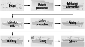
Figure 1 gives an overview of shipbuilding. The initial step is design. The design considerations for various types of ships vary widely. Ships may transport materials or people, may be surface ships or subsurface, may be military or commercial and may be nuclear or non-nuclear powered. In the design phase, not only should normal construction parameters be considered, but the safety and health hazards associated with the construction or repair process must be considered. In addition, environmental issues must be addressed.
Figure 1. Shipbuilding flow chart.
Newport News Shipbuilding
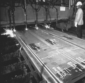
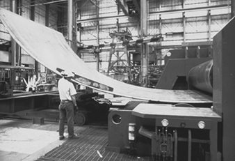
The basic component of ship building is steel plate. The plates are cut, shaped, bent or otherwise manufactured to the desired configuration specified by the design (see figure 2 and figure 3). Typically the plates are cut by an automatic flame cutting process to various shapes. These shapes may be then welded together to form I and T beams and other structural members (see figure 4).
Figure 2. Automatic flame cutting of steel plate in fabrication shop.
Eileen Mirsch
Figure 3. Bending of steel sheet.
Newport News Shipbuilding
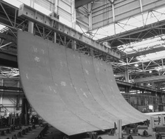
Figure 4. Welded steel plate forming part of a ship's hull.
Newport News Shipbuilding
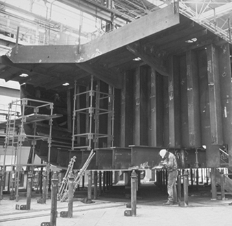
The plates are then sent to fabrication shops, where they are joined into various units and subassemblies (see figure 5). At this juncture, piping, electrical and other utility systems are assembled and integrated into the units. The units are assembled using automatic or manual welding or a combination of the two. Several types of welding processes are employed. The most common is stick welding, in which a consumable electrode is used to join the steel. Other welding processes use inert gas shielded arcs and even non-consumable electrodes.
Figure 5. Working on a ship subassembly
Newport News Shipbuilding
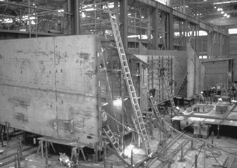
The units or subassemblies are usually then transferred to an open-air platen or lay down area where erection, or joining of assemblies, occurs to form even larger units or blocks (see figure 6) Here, additional welding and fitting occurs. Further, the units and welds must undergo quality-control inspections and testing such as radiography, ultrasonic and other destructive or non-destructive tests. Those welds found defective must be removed by grinding, arc-air grouping or chiseling and then replaced. At this stage the units are abrasive blasted to ensure proper profiling, and painted (see figure 7. Paint may be applied by brush, roller or spray gun. Spraying is most commonly utilized. The paints may be flammable or toxic or pose an environmental threat. Control of abrasive blasting and painting operations must be performed at this time.
Figure 6. Combining of ship subassemblies into larger blocks
Newport News Shipbuilding
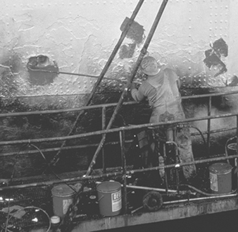
Figure 7. Abrasive blasting of ship units prior to painting.
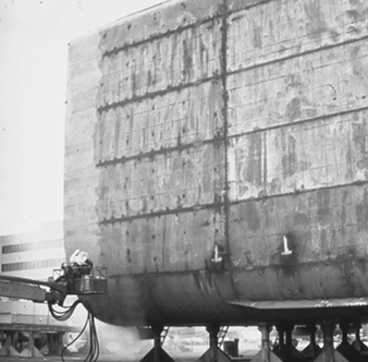
Judi Baldwin
The completed larger units are then moved to the graving dock, shipway or final assembly area. Here, the larger units are joined together to form the vessel (see figure 8) Again, much welding and fitting occur. Once the hull is structurally complete and watertight, the vessel is launched. This may involve sliding it into the water from the shipway on which it was constructed, flooding of the dock in which it was constructed or lowering the vessel into the water. Launchings are almost always accompanied by great celebration and fanfare.
Figure 8. Adding ship's bow to the rest of the vessel.
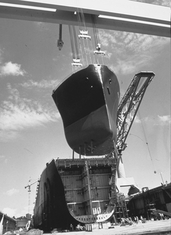
Newport News Shipbuilding
After the ship is launched, it enters the outfitting phase. A large amount of time and equipment are required. The work includes the fitting of cabling and piping, the furnishing of galleys and accommodations, insulation work, installation of electronic equipment and navigation aids and installation of propulsion and ancillary machinery. This work is performed by a wide variety of skilled trades.
After completion of the outfitting phase, the ship undergoes both dock and sea trials, during which all the ship’s systems are proved to be fully functional and operational. Finally, after all testing and associated repair work is performed, the ship is delivered to the customer.
Steel fabrication
A detailed discussion of the steel fabrication process follows. It is discussed in the context of cutting, welding and painting.
Cutting
The “assembly line” of the shipyard starts in the steel storage area. Here, large steel plates of various strengths, sizes, and thicknesses are stored and readied for fabrication. The steel is then blasted with abrasive and primed with a construction primer that preserves the steel during the various phases of construction. The steel plate then is transported to a fabrication facility. Here the steel plate is cut by automatic burners to the desired size (see figure 2). The resulting strips are then welded together to form the structural components of the vessel (figure 4).
Welding
The structural framework of most ships is constructed of various grades of mild and high-strength steel. Steel provides the formability, machinability and weldability required, combined with the strength needed for ocean-going vessels. Various grades of steel predominate in the construction of most ships, although aluminium and other nonferrous materials are used for some superstructures (e.g., deck-houses) and other specific areas within the ship. Other materials found on ships, like stainless steel, galvanized steel and copper-nickel alloy, are used for a variety of corrosion-resistance purposes and to improve structural integrity. However, nonferrous materials are used in far less quantity than steel. Shipboard systems (e.g., ventilation, combat, navigational and piping) are usually where the more “exotic” materials are used. These materials are required to perform a wide variety of functions, including the ship propulsion systems, back-up power, kitchens, pump stations for fuel transfer and combat systems.
Steel used for construction can be subdivided into three types: mild, high-strength and high-alloy steel. Mild steels have valuable properties and are easy to produce, purchase, form and weld. On the other hand, high-strength steels are mildly alloyed to provide mechanical properties that are superior to the mild steels. Extremely high-strength steels have been developed specifically for use in naval construction. In general, the high-strength and high-yield steels are called HY-80, HY-100 and HY-130. They have strength properties in excess of the commercial-grade high-strength steels. More complicated welding processes are necessary for high-strength steels in order to prevent deterioration of their properties. Specific weld rods are needed for high-strength steel, and weld joint heating (preheating) is usually required. A third general class of steels, the high-alloy steels, are made by including relatively large amounts of alloying elements such as nickel, chromium and manganese. These steels, which include stainless steels, have valuable corrosion-resistance properties and also require special welding processes.
Steel is an excellent material for shipbuilding purposes, and the choice of welding electrode is critical in all welding applications during construction. The standard goal is to obtain a weld with equivalent strength characteristics to that of the base metal. Since minor flaws are likely to occur in production welding, welds are often designed and welding electrodes chosen to produce welds with properties in excess of those of the base metal.
Aluminium has found increased application as a shipbuilding metal due to its high strength-to-weight ratio compared to steel. Although the use of aluminium for hulls has been limited, aluminium superstructures are becoming more common for both military and merchant ship construction. Vessels made solely from aluminium are primarily smaller-sized boats, such as fishing boats, pleasure boats, small passenger boats, gunboats and hydrofoils. The aluminium used for shipbuilding and repair is generally alloyed with manganese, magnesium, silicon and/or zinc. These alloys offer good strength, corrosion resistance and weldability.
Shipyard welding processes, or more specifically fusion welding, is performed at nearly every location in the shipyard environment. The process involves joining metals by bringing adjoining surfaces to extremely high temperatures to be fused together with a molten filler material. A heat source is used to heat the edges of the joint, permitting them to fuse with molten weld fill metal (electrode, wire or rod). The required heat is usually generated by an electric arc or a gas flame. Shipyards choose the type of welding process based on customer specifications, production rates and a variety of operating constraints including government regulations. Standards for military vessels are usually more stringent than commercial vessels.
An important factor with respect to the fusion-welding processes is arc shielding to protect the weld pool. The temperature of the weld pool is substantially higher than the adjoining metal’s melting point. At extremely high temperatures, a reaction with oxygen and nitrogen in the atmosphere is rapid and has negative effects on the weld strength. Should oxygen and nitrogen from the atmosphere become trapped within the weld metal and molten rod, embrittlement of the weld area will occur. To protect against this weld impurity and ensure weld quality, shielding from the atmosphere is required. In most welding processes, shielding is accomplished by addition of a flux, a gas or a combination of the two. Where a flux material is used, gases generated by vaporization and chemical reaction at the electrode tip result in a combination of flux and gas shielding that protect the weld from nitrogen and oxygen entrapment. Shielding is discussed in the following sections, where specific welding processes are described.
In electric arc welding, a circuit is created between the work-piece and an electrode or wire. When the electrode or wire is held a short distance away from the work-piece, a high-temperature arc is created. This arc generates sufficient heat to melt the edges of the work-piece and the tip of the electrode or wire to produce a fusion-welding system. There are a number of electric arc welding processes suitable for use in shipbuilding. All processes require shielding of the weld area from the atmosphere. They may be subdivided into flux-shielded and gas-shielded processes.
Manufacturers of welding equipment and associated consumable and non-consumable products report that arc welding with consumable electrodes is the most universal welding process.
Shielded metal arc welding (SMAW). Flux-shielded electric arc welding processes are distinguished primarily by their manual or semi-automatic nature and the type of consumable electrode used. The SMAW process utilizes a consumable electrode (30.5 to 46 cm in length) with a dry flux coating, held in a holder and fed to the work-piece by the welder. The electrode consists of the solid metal filler rod core, made from either drawn or cast material covered with a sheath of metal powders. SMAW is also frequently referred to as “stick welding” and “arc welding”. The electrode metal is surrounded by flux that melts as welding progresses, covering the deposited molten metal with slag and enveloping the immediate area in an atmosphere of protective gas. Manual SMAW may be used for down hand (flat), horizontal, vertical and overhead welding. SMAW processes may also be used semi-automatically through the use of a gravity welding machine. Gravity machines use the weight of the electrode and holder to produce travel along the work-piece.
Submerged arc welding (SAW) is another flux-shielded electric arc welding process used in many shipyards. In this process, a blanket of granulated flux is deposited on the work-piece, followed by a consumable bare metal wire electrode. Generally, the electrode serves as the filler material, although in some cases metal granules are added to the flux. The arc, submerged in the blanket of flux, melts the flux to produce a protective insulated molten shield in the weld zone. High heat concentration permits heavy weld deposits at relatively high speeds. After welding, the molten metal is protected by a layer of fused flux, which is subsequently removed and may be recovered. Submerged arc welding must be performed down hand and is ideally suited to butt welding plates together on panel lines, platen areas and erection areas. The SAW process is generally fully automatic, with equipment mounted on a moving carriage or self-propelled platform on top of the work-piece. Since the SAW process is primarily automatic, a good portion of time is spent aligning the weld joint with the machine. Similarly, since the SAW arc operates under a covering of granulated flux, the fume generation rate (FGR) or fume formation rate (FFR) is low and will remain constant under various operating conditions provided that there is adequate flux cover.
Gas metal arc welding (GMAW). Another major category of electric arc welding comprises the gas-shielded processes. These processes generally use bare wire electrodes with an externally supplied shielding gas which may be inert, active or a combination of the two. GMAW, also commonly referred to as metal inert gas (MIG) welding, uses a consumable, automatically fed, small-diameter wire electrode and gas shielding. GMAW is the answer to a long-sought method of being able to weld continuously without the interruption of changing electrodes. An automatic wire feeder is required. A wire spooling system provides an electrode/wire filler rate that is at a constant speed, or the speed fluctuates with a voltage sensor. At the point where the electrode meets the weld arc, argon or helium being used as the shielding gas is supplied by the welding gun. It was found that for welding steel, a combination of CO2 and/or an inert gas could be used. Often, a combination of the gases is used to optimize cost and weld quality.
Gas tungsten arc welding (GTAW). Another type of gas-shielded welding process is gas tungsten arc welding, sometimes referred to as tungsten inert gas (TIG) welding or the trade name Heliarc, because helium was initially used as the shielding gas. This was the first of the “new” welding processes, following stick welding by about 25 years. The arc is generated between the work-piece and a tungsten electrode, which is not consumed. An inert gas, usually argon or helium, provides the shielding and provides for a clean, low-fume process. Also, the GTAW process arc does not transfer the filler metal, but simply melts the material and the wire, resulting in a cleaner weld. GTAW is most often employed in shipyards for welding aluminium, sheet metal and small-diameter pipes and tubes, or to deposit the first pass on a multi-pass weld in larger pipe and fittings.
Flux core arc welding (FCAW) uses equipment similar to GMAW in that the wire is fed continuously to the arc. The main difference is that the FCAW electrode is a tubular electrode wire with a flux core centre that helps with localized shielding in the welding environment. Some flux cored wire provides adequate shielding with the flux core alone. However, many FCAW processes used in the shipbuilding environment require the addition of gas shielding for the quality requirements of the shipbuilding industry.
The FCAW process provides a high-quality weld with higher production rates and welder efficiency than the traditional SMAW process. The FCAW process allows for a full range of production requirements, such as overhead and vertical welding. FCAW electrodes tend to be a little more expensive than SMAW materials, although in many cases increased quality and productivity are worth the investment.
Plasma-arc welding (PAW). The last of the shielded gas welding processes is plasma-metal inert-gas welding. PAW is very similar to the GTAW process except that the arc is forced to pass through a restriction before reaching the work-piece. The result is a jet stream of intensely hot and fast-moving plasma. The plasma is an ionizing stream of gas that carries the arc, which is generated by constricting the arc to pass through a small orifice in the torch. PAW results in a more concentrated, high-temperature arc, and this permits faster welding. Aside from the use of the orifice to accelerate the gas, PAW is identical to GTAW, using a non-consumable tungsten electrode and an inert gas shield. PAW is generally manual and has minimal use in shipbuilding, although it is sometimes used for flame spraying applications. It is used primarily for steel cutting in the shipbuilding environment (see figure 9).
Figure 9. Underwater Plasma-arc cutting of steel plate

Caroline Kiehner
Gas welding, brazing and soldering. Gas welding employs heat generated by the burning of a gas fuel and generally uses a filler rod for the metal deposited. The most common fuel is acetylene, used in combination with oxygen (oxyacetylene gas welding). A hand-held torch directs the flame to the work-piece while simultaneously melting filler metal which is deposited on the joint. The surface of the work-piece melts to form a molten puddle, with filler material used to fill gaps or grooves. The molten metal, mainly filler metal, solidifies as the torch progresses along the work-piece. Gas welding is comparatively slow and not suitable for use with automatic or semiautomatic equipment. Consequently, it is rarely used for normal production welding in shipyards. The equipment is small and portable, and it can be useful for welding thin plate (up to about 7 mm), as well as for small-diameter pipe, heating, ventilating and air conditioning (HVAC) trunks (sheet metal), electrical cable ways and for brazing or soldering. Identical or similar equipment is used for cutting.
Soldering and brazing are techniques for bonding two metal surfaces without melting the parent metal. A liquid is made to flow into and fill the space between the two surfaces and then solidify. If the temperature of the filler metal is below 450ºC, the process is called soldering; if it is above 450ºC, the process is called brazing. Soldering is commonly done using heat from a soldering iron, flame, electrical resistance or induction. Brazing uses the heat from a flame, resistance or induction. Brazing may also be done by dipping parts in a bath. Soldered and brazed joints do not have the strength properties of welded joints. Consequently, brazing and soldering find limited application in shipbuilding and repair, except for primarily small-diameter pipe joints, sheet metal fabrication, small and infrequent joiner work and maintenance functions.
Other welding processes. There are additional types of welding that may be used in the shipyard environment in small quantities for a variety of reasons. Electroslag welding transfers heat through molten slag, which melts the work-piece and the filler metal. Although the equipment used is similar to that used for electric arc welding, the slag is maintained in a molten state by its resistance to the current passing between the electrode and the work-piece. Therefore, it is a form of electric resistance welding. Often a cooled backing plate is used behind the work-piece to contain the molten pool. Electrogas welding employs a similar setup but uses a flux-coated electrode and CO2 gas shielding. Both of these processes are very efficient for automatically making vertical butt welds and are highly advantageous for thicker plate. These techniques are expected to receive considerably wider application in shipbuilding.
Thermite welding is a process that uses superheated liquid metal to melt the work-piece and provided filler metal. The liquid metal results from a chemical reaction between a melt oxide and aluminium. The liquid metal is poured into the cavity to be welded, and the cavity is surrounded by a sand mould. Thermite welding is somewhat similar to casting and is primarily used to repair castings and forgings or to weld large structural sections such as a stern frame.
Laser welding is a new technology which uses a laser beam to melt and join the work-piece. Although the feasibility of laser welding has been proven, cost has prevented its commercial application to date. The potential for efficient, high-quality welding may make laser welding an important technique for shipbuilding in the future.
Another relatively new welding technique is called electron beam welding. The weld is made by firing a stream of electrons through an orifice to the work-piece, which is surrounded by an inert gas. Electron beam welding does not depend on thermal conductivity of the material to melt the metal. Consequently, both lower energy requirements and reduced metallurgical effects on the steel are significant benefits of this technique. As with laser welding, high cost is a major problem.
Stud welding is a form of electric arc welding in which the stud itself is the electrode. A stud welding gun holds the stud while the arc is formed and the plate and stud end become molten. The gun then forces the stud against the plate and the stud is welded to the plate. Shielding is obtained by the use of a ceramic ferrule surrounding the stud. Stud welding is a semi-automatic process commonly used in shipbuilding to facilitate installation of non-metallic materials, such as insulation, to steel surfaces.
Painting and finish coating
Painting is performed at almost every location in the shipyard. The nature of shipbuilding and repair requires several types of paints to be used for various applications. Paint types range from water-based coatings to high-performance epoxy coatings. The type of paint needed for a certain application depends on the environment to which the coating will be exposed. Paint application equipment ranges from simple brushes and rollers to airless sprayers and automatic machines. In general, shipboard paint requirements exist in the following areas:
- underwater (hull bottom)
- waterline
- topside superstructures
- internal spaces and tanks
- weather decks
- loose equipment.
Many different painting systems exist for each of these locations, but navy ships may require a specific type of paint for every application through a military specification (Mil-spec). There are many considerations when choosing paints, including environmental conditions, severity of environmental exposure, drying and curing times, applications equipment and procedures. Many shipyards have specific facilities and yard locations where painting occurs. Enclosed facilities are expensive, but yield higher quality and efficiency. Open-air painting generally has a lower transfer efficiency and is limited to good weather conditions.
Shipyard paint coating systems. Paints are used for a variety of purposes on a variety of locations on the ships. No one paint can perform all of the desired functions (e.g., rust prevention, anti-fouling and alkaline resistance). Paints are made up of three main ingredients: pigment, a vehicle and a solvent. Pigments are small particles that generally determine the colour as well as the many properties associated with the coating. Examples of pigments are zinc oxide, talc, carbon, coal tar, lead, mica, aluminium and zinc dust. The vehicle can be thought of as the glue that holds the paint pigments together. Many paints are referred to by their binder type (e.g., epoxy, alkyd, urethane, vinyl, phenolic). The binder is also very important for determining the coating’s performance characteristics (e.g., flexibility, chemical resistance, durability, finish). The solvent is added to thin the paint and allow for flowing application to surfaces. The solvent portion of the paint evaporates when the paint dries. Some typical solvents include acetone, mineral spirits, xylene, methyl ethyl ketone and water. Anticorrosive and anti-fouling paints are typically used on ships’ hulls and are the main two types of paint used in the shipbuilding industry. The anticorrosive paints are either vinyl-, lacquer-, urethane- or newer epoxy-based coating systems. The epoxy systems are now very popular and exhibit all of the qualities which the marine environment requires. Anti-fouling paints are used to prevent the growth and attachment of marine organisms on the hulls of vessels. Copper-based paints are widely used as anti-fouling paints. These paints release minute quantities of toxic substances in the immediate vicinity of the vessel’s hull. To achieve different colours, lampblack, red iron oxide or titanium dioxide may be added to the paint.
Shipyard primer coatings. The first coating system applied to raw steel sheets and parts is generally preconstruction primer, which is sometimes referred to as “shop primer”. This coat is important for maintaining the condition of the part throughout the construction process. Preconstruction priming is performed on steel plates, shapes, sections of piping and ventilation ducting. Shop primer has two important functions: (1) preserving the steel material for the final product and (2) aiding in the productivity of construction. Most preconstruction primers are zinc rich, with organic or inorganic binders. Zinc silicates are predominant among the inorganic zinc primers. Zinc coating systems protect coatings in much the same manner as galvanizing. If zinc is coated on steel, oxygen will react with the zinc to form zinc oxide, which forms a tight layer that does not allow water and air to come into contact with the steel.
Paint-applying equipment. There are many types of paint application equipment used in the shipbuilding industry. Two common methods used are compressed-air and airless sprayers. Compressed-air systems spray both air and paint, which causes some paint to atomize (dry) quickly prior to reaching the intended surface. The transfer efficiency of air-assisted spray systems can vary from 65 to 80%. This low transfer efficiency is due mainly to overspray, drift and the air sprayer’s inefficiencies; these sprayers are becoming obsolete because of their low transfer ability.
The most widely used form of paint application in the shipbuilding industry is the airless sprayer. The airless sprayer is a system which simply compresses paint in a hydraulic line and has a spray nozzle at the end; hydrostatic pressure, instead of air pressure, conveys the paint. To reduce the amount of overspray and spillage, shipyards are maximizing the use of airless paint sprayers. Airless sprayers are much cleaner to operate and have fewer leaking problems than compressed-air sprayers because the system requires less pressure. Airless sprayers have close to 90% transfer efficiency, depending on the conditions. A new technology which can be added to the airless sprayer is called high volume, low pressure (HVLP). HVLP offers an even higher transfer efficiency, in certain conditions. Measurements of transfer efficiency are estimates and include allowances for drips and spills which can occur when painting.
Thermal spray, also known as metal or flame spray, is the application of aluminium or zinc coatings to steel for long-term corrosion protection. This coating process is used on a wide variety of commercial and military applications. It is significantly different from conventional coating practices due to its specialized equipment and relatively slow production rates. There are two basic types of thermal coating machines: combustion wire and arc spray. The combustion wire type consists of combustible gases and a flame system with a wire feed controller. The combustible gases melt the material to be sprayed onto the parts. The electric arc spray machine instead uses a power supply arc to melt the flame sprayed material. This system includes an air-compression and filtration system, a power arc supply and controller and an arc flame spray gun. The surface must be properly prepared for proper adhesion of flame sprayed materials. The most common surface preparation technique is air blasting with fine grit (e.g., aluminium oxide).
The initial cost of thermal spray is usually high compared to painting, although when the lifecycle is taken into account, thermal spray becomes more economically attractive. Many shipyards have their own thermal spray machines, and other shipyards will subcontract their thermal coating work. Thermal spray can be done in a shop or on board the ship.
Painting practices and methods. Painting is performed in nearly every area in the shipyard, from the initial priming of the steel to the final paint detailing of the ship. Methods for painting vary greatly from process to process. Mixing of paint is performed both manually and mechanically and is usually done in an area surrounded by berms or secondary containment pallets; some of these are covered areas. Outdoor as well as indoor painting occurs in the shipyard. Shrouding fences, made of steel, plastic or fabric, are frequently used to help contain paint overspray or to block the wind and catch paint particles. New technology will aid in reducing the amount of airborne particles. Reducing the amount of overspray also reduces the amount of paint used and thus saves the shipyard money.
Surface preparation and painting areas in the shipyard
To illustrate painting and surface preparation practices in the shipbuilding and repair industry, practices can be generically described in five main areas. The following five areas help to illustrate how painting occurs in the shipyard.
Hull painting. Hull painting occurs on both repair ships and new construction ships. Hull surface preparation and painting on repair ships is normally performed when the ship is fully drydocked (i.e., on the graving dock of a floating drydock). For new construction, the hull is prepared and painted at a building position using one of the techniques discussed above. Air and/or water blasting with mineral grit are the most common types of surface preparation for hulls. Surface preparation involves blasting the surface from platforms or lifts. Similarly, paint is applied using sprayers and high-reach equipment such as man-lifts, scissor lifts or portable scaffolding. Hull painting systems vary in the number of coats required.
Superstructure painting. The superstructure of the ship consists of the exposed decks, deck houses and other structures above the main deck. In many cases, scaffolding will be used on board the ship to reach antennas, houses and other superstructures. If it is likely that paint or blast material will fall into adjacent waters, shrouding is put into place. On ships being repaired, the ship’s superstructure is painted mostly while berthed. The surface is prepared using either hand tools or air-nozzle blasting. Once the surface is prepared and the associated surface materials and grit are cleaned up and disposed of, then painting can commence. Paint systems usually are applied with airless paint sprayers. The painters access the superstructures with existing scaffolding, ladders and various lifting equipment that was used during surface preparation. The shrouding system (if applicable) that was used for blast containment will stay in place to help contain any paint overspray.
Interior tank and compartment painting. Tanks and compartments on board ships must be coated and re-coated to maintain the longevity of the ship. Re-coating of repair ship tanks requires a large amount of surface preparation prior to painting. The majority of the tanks are at the bottom of the ship (e.g., ballast tanks, bilges, fuel tanks). The tanks are prepared for paint by using solvents and detergents to remove grease and oil build-up. The wastewater developed during tank cleaning must be properly treated and disposed of. After the tanks are dried, they are abrasive blasted. During the blasting operation, the tank must have recirculating air and the grit must be vacuumed out. The vacuum systems used are either of a liquid ring or rotary screw type. These vacuums must be very powerful to remove the grit from the tank. The vacuum systems and ventilation systems are generally located on the dock’s surface, and access to the tanks is through holes in the hull. Once the surface is blasted and the grit is removed, painting can begin. Adequate ventilation and respirators are required for all tank and compartment surface preparation and painting (i.e., in enclosed or confined spaces).
Paint surface preparation as stages of construction. Once the blocks, or multiple units, leave the assembly area, they are frequently transported to a blast area where the entire block is prepared for paint. At this point, the block is usually blasted back down to bare metal (i.e., the construction primer is removed) (see figure 7 ). The most frequent method for block surface preparation is air-nozzle blasting. The next stage is the paint application stage. Painters generally use airless spray equipment on access platforms. Once the block’s coating system has been applied, the block is transported to the on-block stage, where outfitting materials are installed.
Small parts painting areas. Many parts comprising a ship need to have a coating system applied to them prior to installation. For example, piping spools, vent ducting, foundations and doors are painted before they are installed on block. Small parts are generally prepared for paint in a designated area of the shipyard. Small parts painting can occur in another designated location in the shipyard that best matches production needs. Some small parts are painted in the various shops, while others are painted in a standard location operated by the paint department.
Surface preparation and painting on block and on board
Final painting of the ship occurs on board, and touch-up painting will frequently occur on block (see figure 10). On-block touch-up painting occurs for several reasons. In some cases, paint systems are damaged on block and need to be resurfaced, or perhaps the wrong paint system was applied and needs to be replaced. On-block painting involves using portable blasting and painting equipment throughout the on-block outfitting areas. On-board painting involves preparing and painting the interface sections between the construction blocks and repainting areas damaged by welding, rework, on-board outfitting and other processes. The surfaces can be prepared by hand tools, sanding, brushing, solvent cleaning or any of the other surface preparation techniques. Paint is applied with portable airless sprayers, rollers and brushes.
Figure 10. Touch-up painting on a ship's hull.
Newport News Shipbuilding
Outfitting
Pre-erection outfitting of construction blocks is the current shipbuilding method used by all competitive shipbuilders worldwide. Outfitting is the process of installing parts and various subassemblies (e.g., piping systems, ventilation equipment, electrical components) on the block prior to joining the blocks together at erections. The outfitting of blocks throughout the shipyard lends itself to forming an assembly line approach to shipbuilding.
Outfitting at each stage of construction is planned to make the process flow smoothly throughout the shipyard. For simplicity, outfitting can be divided into three main stages of construction once the steel structure of the block has been assembled:
- unit outfitting
- on-block outfitting
- on-board outfitting.
Unit outfitting is the stage where fittings, parts, foundations, machinery and other outfitting materials are assembled independent of the hull block (i.e., units are assembled separate from steel structural blocks). Unit outfitting allows workers to assemble shipboard components and systems on the ground, where they have easy access to the machinery and workshops. Units are installed at either the on-board or the on-block stage of construction. Units come in varying sizes, shapes and complexities. In some cases, units are as simple as a fan motor connected to a plenum and coil. Large, complex units are mainly composed of components in machinery spaces, boilers, pump rooms and other complex areas of the ship. Unit outfitting involves assembling piping spools and other components together, then connecting the components into units. Machinery spaces are areas on the ship where machinery is located (e.g., engine rooms, pump stations and generators) and outfitting there is intensive. Outfitting units on the ground increases safety and efficiency by reducing the work hours that would otherwise be allocated to on-block or on-board work in more confined spaces where conditions are more difficult.
On-block outfitting is the stage of construction where most of the outfitting material is installed onto the blocks. Outfitting materials installed on block consist of ventilation systems, piping systems, doors, lights, ladders, railings, electrical assemblies and so on. Many units are also installed at the on-block stage. Throughout the on-block outfitting stage, the block can be lifted, rotated and moved to efficiently facilitate installing outfitting materials on the ceilings, walls and floors. All of the shops and services in the shipyard must be in communication at the on-block stage to ensure that materials are installed at the right time and place.
On-board outfitting is performed after the blocks are lifted onto the ship under construction (i.e., after erection). At this time, the ship is either at a building position (building ways or building dock), or the ship could be berthed at pierside. The blocks are already outfitted to a large extent, although much more work is still needed before the ship is ready to operate. On-board outfitting involves the process of installing large units and blocks on board the ship. Installation includes lifting the large blocks and units on board the new ship and welding or bolting them into place. On-board outfitting also involves connecting the shipboard systems together (i.e., piping system, ventilation system and electrical system). All of the wiring systems are pulled throughout the ship at the on-board stage.
Testing
The operation and test stage of construction assesses the functionality of installed components and systems. At this stage, systems are operated, inspected and tested. If the systems fail the tests for any reason, the system must be repaired and retested until it is fully operational. All piping systems on board the ship are pressurized to locate leaks that may exist in the system. Tanks also need structural testing, which is accomplished by filling the tanks with fluids (i.e., salt water or fresh water) and inspecting for structural stability. Ventilation, electrical and many other systems are tested. Most system testing and operations occur while the ship is docked at pierside. However, there is an increasing trend to perform testing at earlier stages of construction (e.g., preliminary testing in the production shops). Performing tests at earlier stages of construction makes it easier to fix failures because of the increased accessibility to the systems, although complete systems tests will always need be done on board. Once all preliminary pierside testing is performed, the ship is sent to sea for a series of fully operational tests and sea trials before the ship is delivered to its owner.
Ship Repair
Steel ship repair practices and processes
Ship repair generally includes all ship conversions, overhauls, maintenance programmes, major damage repairs and minor equipment repairs. Ship repair is a very important part of the shipping and shipbuilding industry. Approximately 25% of the labour force in most private shipbuilding shipyards does repair and conversion work. Currently there are many ships that need updating and/or conversions to meet safety and environmental requirements. With fleets worldwide becoming old and inefficient, and with the high cost of new ships, the situation is putting a strain on shipping companies. In general, conversion and repair work in US shipyards is more profitable than new construction. In new-construction shipyards, repair contracts, overhauls and conversions also help to stabilize the workforce during times of limited new construction, and new construction augments the repair labour workload. The ship repair process is much like the new construction process, except that it is generally on a smaller scale and is performed at a faster pace. The repair process requires a more timely coordination and an aggressive bidding process for ship repair contracts. Repair work customers are generally the navy, commercial ship owners and other marine structure owners.
The customer usually provides contract specifications, drawings and standard items. Contracts can be firm fixed price (FFP), firm fixed price award fee (FFPAF), cost plus fixed fee (CPFF), cost plus award fee (CPAF) or urgent repair contracts. The process starts in the marketing area when the shipyard is asked for a request for proposal (RFP) or an invitation for bid (IFB). The lowest price usually wins an IFB contract, while a RFP award can be based on factors other than price. The repair estimating group prepares the cost estimate and the proposal for the repair contract. Bid estimates generally include worker-hours and wage rates, materials, overhead, special service costs, subcontractor dollars, overtime and shift premiums, other fees, facilities cost of money and, based on these, the estimated price of the contract. Once the contract is awarded, a production plan must be developed.
Repair planning, engineering and production
Although some preliminary planning is performed at the proposal stage of the contract, much work is still needed to plan and execute the contract in a timely manner. The following steps should be accomplished: read and understand all contract specifications, categorize the work, integrate the work into a logical production plan and determine the critical path. Planning, engineering, materials, subcontracts and repair production departments must work closely together to perform the repair in the most timely and cost-effective manner. Prefabrication of piping, ventilation, electrical and other machinery is performed, in many cases, prior to the ship’s arrival. Pre-outfitting and prepackaging of repair units takes cooperation with the production shops to perform work in a timely manner.
Common types of repair work
Ships are similar to other types of machinery in that they require frequent maintenance and, sometimes, complete overhauls to remain operational. Many shipyards have maintenance contracts with shipping companies, ships and/or ship classes that identify frequent maintenance work. Examples of maintenance and repair duties include:
- blasting and repainting the ship’s hull, freeboard, superstructure, interior tanks and work areas
- major machinery rebuilding and installation (e.g., diesel engines, turbines, generators and pump stations)
- systems overhauls, maintenance and installation (e.g., flushing, testing and installation of a piping system)
- new system installation, either adding new equipment or replacing systems that are outdated (e.g., navigational systems, combat systems, communication systems or updated piping systems)
- propeller and rudder repairs, modification and alignment
- creation of new machinery spaces on the ship (e.g., cut-out of existing steel structure and adding new walls, stiffeners, vertical supports and webbing).
In many cases, repair contracts are an emergency situation with very little warning, which makes ship repair a fast moving and unpredictable environment. Normal repair ships will stay in the shipyard from 3 days to 2 months, while major repairs and conversions can last more than a year
Large repairs and conversion projects
Large repair contracts and major conversions are common in the ship repair industry. Most of these large repair contracts are performed by shipyards that have the ability to construct ships, although some primarily repair yards will perform extensive repairs and conversions.
Examples of major repair contracts are as follows:
- conversion of supply ships to hospital ships
- cutting a ship in half and installing a new section to lengthen the ship (see figure 11)
- replacing segments of a ship that has run aground (see figure 12)
- complete rip-out, structural reconfiguration and outfitting of combat systems
- major remodelling of ship’s interior or exterior (e.g., complete overhauls of passenger cruise ships).
Most major repairs and conversions require a large planning, engineering and production effort. In many cases, a large quantity of steel work will need to be accomplished (e.g., major cut-out of existing ship structure and installation of new configurations). These projects can be divided into four major stages: removal, building new structure, equipment installation and testing. Subcontractors are required for most major and minor repairs and conversions. The subcontractors provide expertise in certain areas and help to even the workload in the shipyard.
Figure 11. Cutting a ship in half in order to install a new section.
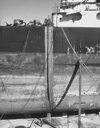
Newport News Shipbuilding
Figure 12. Replacing the prow of a ship that ran aground.

Newport News Shipbuilding
Some of the work that subcontractors perform are as follows:
-
support of ship repair
-
major combat systems installations (technical)
-
boiler re-tubing and rebuilding
-
air compressor overhauls
-
asbestos removal and disposal
-
tank cleaning
-
blasting and painting
-
pump system overhauls
-
small structural fabrication
-
winch overhauls
-
main steam system modifications
-
system fabrications (i.e., piping, ventilation, foundations and so on).
As with new construction, all installed systems must be tested and operational before the ship is returned to its owner. Testing requirements generally originate from the contract, although other sources of testing requirements do exist. The tests must be scheduled, tracked for proper completion and monitored by the proper groups (shipyard internal quality, vessel operation, government agencies, shipowners and so on). Once systems are in place and properly tested, the area, compartment and/or system can be considered sold to the ship (i.e., completed).
There are many similarities between new construction and repair processes. The primary similarities are that they both use the application of essentially the same manufacturing practices, processes, facilities and support shops. Ship repair and new construction work require highly skilled labour because many of the operations have limited potential for automation (especially ship repair). Both require excellent planning, engineering and interdepartmental communications. The repair process flow is generally as follows: estimate, plan and engineer the job; rip-out work; refitting of steel structures; repair production; test and trials; and deliver the ship. In many ways the ship repair process is similar to shipbuilding, although new construction requires a greater amount of organization because of the size of the workforce, size of the workload, number of parts and the complexity of the communications (i.e., production plans and schedules) surrounding the shipbuilding work flow.
Hazards and Precautions
Shipbuilding and repair is one of the most hazardous industries. Work must be done in a variety of highly hazardous situations, such as confined spaces and considerable heights. Much manual work is performed involving heavy equipment and material. Since the work is so interrelated, the results of one process may endanger personnel involved in another process. In addition, a great portion of work is performed out-of-doors, and the effects of weather extremes can cause or aggravate hazardous conditions. Additionally, a number of chemicals, paints, solvents and coatings must be used, which may pose significant risks to employees.
Health hazards
Chemical hazards which pose health risks to employees in shipyards include:
- dusts from abrasive blasting operations
- exposure to asbestos and mineral fibres in insulation work
- vapours and spray mists from paints, coatings, solvents and thinners
- fumes from various welding, burning, soldering and brazing operations
- exposure to gases used in various welding, burning and heating processes
- exposure to specific toxic chemicals in epoxy resins, organo-tin and copper anti-fouling paints, lead paint, oils, greases, pigments and the like.
Physical hazards due to the manual nature of the work include:
- temperature and weather extremes associated with work performed out-of-doors
- electrical hazards
- ergonomic-related problems caused by repetitive handling of large and bulky materials
- ionizing and non-ionizing radiation
- noise and vibration
- oxygen deficiency potential and other confined space hazards associated with tanks, double bottoms and so on
- falls and trips from work on the same level as well as work from great heights.
Preventive measures
Although shipbuilding and repair is a very hazardous industry, the risks to personnel by these hazards can and should be minimized. The basis for hazard reduction is a well-founded health and safety programme that is rooted in a good partnership between management and the trade unions or employees. There are a number of approaches that can be utilized to prevent or minimize hazards in shipyards once they are identified. These approaches may be broadly divided into several strategies. Engineering controls are employed to eliminate or control hazards at their point of generation. These controls are the most desirable of the various types since they are most dependable:
-
Substitution or elimination. Where possible, processes that produce hazards or toxic materials should be eliminated or replaced with less hazardous processes or materials. This is the most effective form of control. An example is the use of non-carcinogenic materials instead of asbestos insulation. Another example is the use of hydraulic lifting tables for handling heavy materials, instead of manual lifting. Replacement of solvent-based paints with water-based coatings is frequently possible. Automation or robotics can be used to eliminate process hazards.
-
Isolation. Processes that are not amenable to substitution or elimination can sometimes be isolated from employees to minimize exposures. Frequently, sources of high noise can be relocated to place more distance between workers and the noise source, thus reducing exposure.
-
Enclosure. Processes or personnel can sometimes be enclosed to eliminate or reduce exposures. Operators of equipment can be provided enclosed booths to minimize exposure to noise, heat, cold or even chemical hazards. Processes may also be enclosed. Paint-spray booths and welding booths are examples of process enclosure that reduce exposures to potentially toxic materials.
-
Ventilation. Processes that produce toxic materials can be ventilated to capture the materials at their point of generation. This technique is used extensively in shipyards and boatyards, particularly to control welding fumes and gases, paint vapours and the like. Many fans and blowers are located on the decks of vessels and air is either exhausted from or blown into spaces to reduce exposure to hazards. Frequently fans are used in the blowing mode to direct fresh air into compartments to maintain acceptable oxygen levels.
Administrative controls are used to minimize exposures by administratively limiting the time spent by personnel in potentially hazardous situations. This is generally accomplished by rotating personnel from a relatively low hazard job to a higher hazard one. Although the aggregate amount of person-exposure time is not changed, exposure of each individual worker is reduced.
Administrative controls are not without their negative aspects. This technique requires additional training since workers must know both jobs and more workers are potentially exposed to a hazard. Also, since the number of personnel exposed to hazards has doubled from a legal standpoint, potential liabilities may be increased. However, administrative control can be an effective method if properly applied.
Personal protective controls. Shipyards must rely heavily on the various forms of personal protection. The nature of ship construction and repair does not lend itself to traditional engineering approaches. Ships are very confined spaces with limited access. A submarine under repair has 1 to 3 hatches that are .76 m in diameter, through which people and equipment must pass. The amount of ventilation tubing that can pass through is severely limited. Similarly, on large ships work is performed deep within the vessel, and although some ventilation may be smoked through the various levels to reach the desired operation, the amount is limited. Further, the fans pushing or pulling air through the vent tubing are generally located in fresh air, usually on a main deck, and they, too, have somewhat limited capacity.
In addition, ship construction and repair is not performed in an assembly line, but in separate work sites such that stationary engineering controls are impractical. Further, a ship may be under repair for a few days, and the extent to which engineering control may be utilized is again limited. Personal protective equipment is used extensively in these situations.
In shops, more extensive use may be made of traditional engineering control approaches. Most equipment and machinery in shops and assembly platens is very amenable to traditional guarding, ventilation and other engineering approaches. However, some personal protective equipment must be utilized in these situations as well.
A discussion of the various applications of personal protective equipment utilized in shipyards follows:
Welding, cutting and grinding. The basic process of constructing and repairing ships involves cutting, shaping and joining steel and other metals. In the process, metallic fumes, dusts and particulates are generated. Although ventilation can sometimes be utilized, more frequently welders must utilize respirators for protection from welding particulates and fumes. In addition, they must employ appropriate eye protection for ultraviolet and infrared illumination and other physical eye and face hazards. In order to provide protection from sparks and other forms of molten metal, the welder must be protected by welding gloves, long-sleeved clothing and other physical protection.
Abrasive blasting and painting. Much painting is performed in ship construction and repair. In many cases, the paints and coatings are specified by the ship’s owner. Prior to painting, the equipment must be blasted with an abrasive to a certain profile that ensures good adhesion and protection.
Abrasive blasting of small parts may be performed in a closed system such as a glove box. However, most large components are abrasive blasted manually. Some blasting is performed in the open air, some in large bays of a building or shop designated for this purpose and some inside the vessels or vessel sections themselves. In any case, personnel performing abrasive blasting must use full-body protection, hearing protection and air-fed respiratory protection. They must be provided with an adequate supply of breathable air (i.e., at least Grade D breathing air).
In some countries the use of crystalline silica has been banned. Its use is generally not recommended. If silica-containing materials are used in blasting, preventive protective measures must be taken.
After abrasive blasting, materials must be quickly painted in order to prevent “flash rusting” of the surface. Although mercury, arsenic and other very toxic metals are no longer used in paints, paints used in shipyards generally contain solvents as well as pigments such as zinc. Other paints are of the epoxy type. Painters who apply these coatings must be protected. Most painters must use a negative or positive pressure respirator for their protection, as well as full-body coveralls, gloves, shoe covers and eye protection. Sometimes painting must be performed in confined or enclosed spaces. In these cases, air-supplied respiratory protection and full-body protection must be used, and there must be an adequate, permit-requiring confined-spaces programme.
Overhead hazards. Shipyards have many cranes, and a large amount of overhead work is performed. Hard-hat protection is generally required in all production areas of shipyards.
Insulation work. Piping systems and other components must be insulated to maintain component temperature and reduce heat in the ship’s interior; in some cases, insulation is needed for noise reduction. In ship repair, existing insulation must be removed from piping to do repair work; in these cases, asbestos material is frequently encountered. In new work, fibreglass and mineral fibres are frequently used. In either case, appropriate respiratory protection and full-body protection must be worn.
Noise sources. Work in shipyards is notoriously noisy. Most processes involve working with metal; this typically produces noise levels above acceptable safe limits. Not all noise sources can be controlled to safe levels by utilizing engineering controls. Thus, personal protection must be used.
Foot hazards. Shipyards have a number of operations and processes that present hazards to the feet. It is often difficult and impractical to segregate the facility into foot hazard and non-foot hazard areas; safety shoes/boots are typically required for the entire production area of shipyards.
Eye hazards. There are many potential sources of hazards to the eyes in shipyards. Examples are various ultraviolet and infrared light hazards from welding arcs, physical hazards from various metal working dusts and particles, abrasive blasting grit, work with various pickling and metal baths, caustics and paint sprays. Due to the ubiquitous nature of these hazards, safety glasses are frequently required throughout the production areas of shipyards for practical and administrative simplicity. Special eye protection is required for specific individual processes.
Lead. Over the years, lead-based primers and coatings have been utilized extensively in ship construction. Although lead-containing paints and coatings are rarely used today, a significant amount of elemental lead is used in nuclear shipyards as a radiation shielding material. In addition, ship repair work often involves the removal of older coatings that frequently contain lead. In fact, repair work requires a great deal of sensitivity and concern for materials that have been applied or used previously. Work with lead requires full-body protection including coveralls, gloves, hat, shoe covers and respiratory protection.
Boat Building
In some ways boats can be thought of as relatively small ships in that many of the processes used to construct and repair boats are very similar to those used to construct and repair ships, only on a smaller scale. Generally, steel, wood and composites are chosen for construction of boat hulls.
Composites include, in general, such materials as fibre-reinforced metals, fibre-reinforced cement, reinforced concrete, fibre-reinforced plastics and glass-reinforced plastics (GRPs). Development during the early 1950s of hand lay-up methods employing cold-cure polyester resin with glass reinforcement led to a rapid expansion of GRP boat construction, from 4% in the 1950s to over 80% in the 1980s and even higher currently.
In vessels over 40 m or so in length, steel rather than wood is the main alternative to GRP. As hull size is reduced, the relative cost of steel construction increases, becoming generally uncompetitive for hulls under 20 m in length. The need for corrosion margin tends also to lead to excessive weight in small steel boats. For vessels over 40 m, however, the low cost of heavy welded steel construction is normally a decisive advantage. Unless imaginative design, improved materials and automated fabrication can bring about a substantial reduction in costs, however, glass- or fibre-reinforced plastics seem unlikely to become competitive with steel for construction of ships over about 40 m in length except where special requirements exist (e.g., for transportation of corrosive or cryogenic bulk cargo, where a nonmagnetic hull is required or where substantial weight saving is necessary for performance reasons).
GRPs are now employed in a very wide range of boat hull applications including speedboats, coastal and ocean-going yachts, work boats, pilot and passenger launches and fishing boats. Its success in fishing boats, where wood has been the traditional material, is attributable to:
-
competitive first cost, particularly where many hulls are built to the same design, enhanced by the increasing cost of wood and scarcity of skilled woodworkers
-
trouble-free performance and low maintenance costs resulting from leak-proof, rot-proof qualities of GRP hulls, their resistance to marine boring organisms and low cost of repair
-
the ease with which complex shapes, which may be required for hydrodynamic and structural purposes or for aesthetic reasons, can be fabricated.
Fabrication methods
The most common form of construction for shells, decks and bulkheads in large and small GRP hulls is single-skin laminate reinforced as necessary by stiffeners. Various methods of fabrication are employed in the construction of single-skin and sandwich hulls.
Contact moulding. By far the most common method of fabrication for single-skin GRP hulls of all sizes is contact moulding in an open or negative mould using cold-curing polyester resin and E-glass reinforcement.
The first step in the fabrication process is mould preparation. For hulls of small and moderate size, moulds are usually fabricated in GRP, in which case a positive plug, commonly of wooden construction finished in GRP, is first assembled, whose external surface accurately defines the required hull shape. Mould preparation is generally completed by wax polishing and application of a film of polyvinyl alcohol (PVA) or equivalent release agent. Laminating is usually started by application of pigmented gel coat of good-quality resin. Laminating is then continued, before the gel coat has fully cured, using one of the following processes:
-
Spray up. Glass fibre rovings or reinforcements are sprayed simultaneously with polyester resin, the latter being mixed with catalyst and accelerator at the spray gun.
-
Hand lay-up. Resin mixed with catalyst and accelerator is deposited liberally on the gel coat or on a previous ply of impregnated reinforcement by brush, roller-dispenser or spray gun.
The process outlined above can achieve efficient application of very heavy reinforcement (fabric of up to 4,000 g/m2 has been used successfully, although for large-scale production a fabric weight of 1,500 to 2,000 g/m2 has been preferred), giving a rapid laminating rate with low labour costs. A similar process can be applied for rapid lay-up of flat or nearly flat deck and bulkhead panels. Batch production of certain 49 m hulls, including installation of decks and bulkheads, has been achieved with a completion time of 10 weeks per hull.
Compression moulding. Compression moulding involves application of pressure, possibly accompanied by heat, to the surface of an uncured laminate, to increase fibre content and reduce voids by squeezing out excess resin and air.
Vacuum bag moulding. This process, which may be regarded as an elaboration of contact moulding, involves placing over the mould a flexible membrane, separated from the uncured laminate by a film of PVA, polythene or equivalent material, sealing the edges and evacuating the space under the membrane so that the laminate is subjected to a pressure of up to l bar. Curing may be speeded by placing the bagged component in an oven or employing a heated mould.
Autoclave moulding. Higher pressures (e.g., 5 to 15 bar) combined with elevated temperature, yielding increased fibre content and hence superior mechanical properties, may be achieved by carrying out the bag moulding process in an autoclave (pressurized oven).
Matched die moulding. The uncured moulding material, which in a large component such as a boat hull is likely to be a sprayed premix of resin and chopped-strand glass or a tailored preform of pre-impregnated glass fabric, is compressed between matched positive and negative moulds, usually of metallic construction, with application of heat if required. Because of the high first cost of moulds, this process is likely to be economical only for large production runs and is rarely used for boat hull fabrication.
Filament winding. Fabrication in this process is carried out by winding reinforcing fibres, in the form of a continuous roving which may be impregnated with resin just prior to winding (wet-winding) or may be pre-impregnated with partially cured resin (dry-winding), onto a mandrel which defines the internal geometry.
Sandwich construction. Sandwich hulls, decks and bulkheads may be fabricated by contact moulding, using room-temperature curing polyester resin, in much the same way as single-skin structures. The outer GRP skin is first laid up on the negative mould. Strips of core material are embedded on a layer of polyester or epoxy resin. Fabrication is then completed by laying up the internal GRP skin.
Polyester and epoxy resins. Unsaturated polyester resins are by far the most commonly used matrix materials for marine structural laminates. Their effectiveness follows from their moderate cost, ease of use within hand lay-up or spray-up fabrication processes and generally good performance in a marine environment. Three main types are available:
-
Orthophthalic polyester, made by a combination of maleic and phthalic anhydrides with a glycol (commonly propylene glycol), is the least expensive and most widely used matrix material for small boat construction.
-
Isophthalic polyester, containing isophthalic acid in place of phthalic anhydride, is more expensive, has somewhat superior mechanical properties and water resistance and is commonly specified for higher-performance boat construction and marine gel coats.
-
Bisphenol epoxy systems, in which phthalic acid or anhydride is partly or completely replaced by bisphenol A, offers (at substantially higher cost) much improved water and chemical resistance.
Safety and health hazards
Although many of the chemical, physical and biological hazards in shipbuilding are common to boat building, a primary concern is exposure to various solvent vapours and epoxy dusts from the boat manufacturing process. Uncontrolled exposure to these hazards may produce central nervous system disorders, liver and kidney damage, and sensitization reactions, respectively. The controls for these potential hazards are essentially the same as those described previously in the shipbuilding section—namely, engineering controls, administrative controls and personal protective controls.