Machinery, process plants and other equipment can, if they malfunction, present risks from hazardous events such as fires, explosions, radiation overdoses and moving parts. One of the ways such plants, equipment and machinery can malfunction is from failures of electro-mechanical, electronic and programmable electronic (E/E/PE) devices used in the design of their control or safety systems. These failures can arise either from physical faults in the device (e.g., from wear and tear occurring randomly in time (random hardware failures)); or from systematic faults (e.g., errors made in the specification and design of a system that cause it to fail due to (1) some particular combination of inputs, (2) some environmental condition (3) incorrect or incomplete inputs from sensors, (4) incomplete or erroneous data entry by operators, and (5) potential systematic faults due to poor interface design).
Safety-Related Systems Failures
This article covers the functional safety of safety-related control systems, and considers the hardware and software technical requirements necessary to achieve the required safety integrity. The overall approach is in accordance with the proposed International Electrotechnical Commission Standard IEC 1508, Parts 2 and 3 (IEC 1993). The overall goal of draft international standard IEC 1508, Functional Safety: Safety-Related Systems, is to ensure that plant and equipment can be safety automated. A key objective in the development of the proposed international standard is to prevent or minimize the frequency of:
- failures of control systems triggering other events which in turn could lead to danger (e.g., control system fails, control is lost, process goes out of control resulting in a fire, release of toxic materials, etc.)
- failures in alarm and monitoring systems so that operators are not given information in a form that can be quickly identified and understood in order to carry out the necessary emergency actions
- undetected failures in protection systems, making them unavailable when needed for a safety action (e.g., a failed input card in an emergency shut-down system).
The article “Electrical, electronic and programmable electronic safety-related systems” sets out the general safety management approach embodied within Part 1 of IEC 1508 for assuring the safety of control and protection systems that are important to safety. This article describes the overall conceptual engineering design that is needed to reduce the risk of an accident to an acceptable level, including the role of any control or protection systems based on E/E/PE technology.
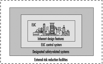
In figure 1, the risk from the equipment, process plant or machine (generally referred to as equipment under control (EUC) without protective devices) is marked at one end of the EUC Risk Scale, and the target level of risk that is needed to meet the required level of safety is at the other end. In between is shown the combination of safety-related systems and external risk reduction facilities needed to make up the required risk reduction. These can be of various types—mechanical (e.g., pressure relief valves), hydraulic, pneumatic, physical, as well as E/E/PE systems. Figure 2 emphasizes the role of each safety layer in protecting the EUC as the accident progresses.
Figure 1. Risk reduction: General concepts
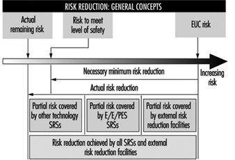
Figure 2. Overall model: Protection layers
Provided that a hazard and risk analysis has been performed on the EUC as required in Part 1 of IEC 1508, the overall conceptual design for safety has been established and therefore the required functions and Safety Integrity Level (SIL) target for any E/E/PE control or protection system have been defined. The Safety Integrity Level target is defined with respect to a Target Failure Measure (see table 1).
Table 1. Safety Integrity Levels for protection systems: Target failure measures
Safety integrity Level Demand mode of operation (Probability of failure to perform its design function on demand)
4 10-5 ≤ × 10-4
3 10-4 ≤ × 10-3
2 10-3 ≤ × 10-2
1 10-2 ≤ × 10-1
Protection Systems
This paper outlines the technical requirements that the designer of an E/E/PE safety-related system should consider to satisfy the required Safety Integrity Level target. The focus is on a typical protection system utilizing programmable electronics in order to allow for a more in-depth discussion of the key issues with little loss in generality. A typical protection system is shown in figure 3, which depicts a single channel safety system with a secondary switch-off activated via a diagnostic device. In normal operation the unsafe condition of the EUC (e.g., overspeed in a machine, high temperature in a chemical plant) will be detected by the sensor and transmitted to the programmable electronics, which will command the actuators (via the output relays) to put the system into a safe state (e.g., removing power to electric motor of the machine, opening a valve to relieve pressure).
Figure 3. Typical protection system
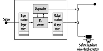
But what if there are failures in the protection system components? This is the function of the secondary switch-off, which is activated by the diagnostic (self-checking) feature of this design. However, the system is not completely fail-safe, as the design has only a certain probability of being available when being asked to carry out its safety function (it has a certain probability of failure on demand or a certain Safety Integrity Level). For example, the above design might be able to detect and tolerate certain types of output card failure, but it would not be able to withstand a failure of the input card. Therefore, its safety integrity will be much lower than that of a design with a higher-reliability input card, or improved diagnostics, or some combination of these.
There are other possible causes of card failures, including “traditional” physical faults in the hardware, systematic faults including errors in the requirements specification, implementation faults in the software and inadequate protection against environmental conditions (e.g., humidity). The diagnostics in this single-channel design may not cover all these types of faults, and therefore this will limit the Safety Integrity Level achieved in practice. (Coverage is a measure of the percentage of faults that a design can detect and handle safely.)
Technical Requirements
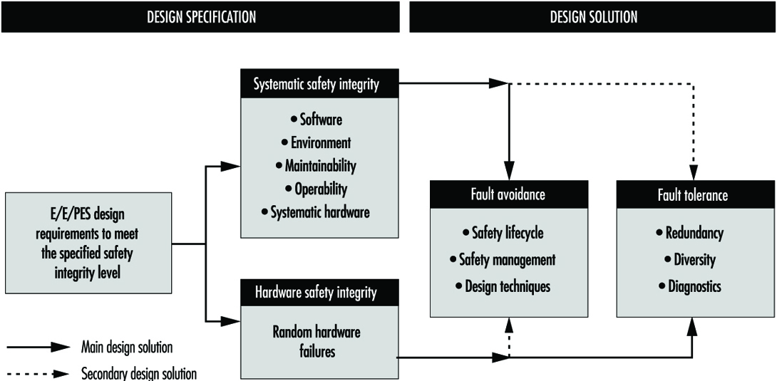
Parts 2 and 3 of draft IEC 1508 provide a framework for identifying the various potential causes of failure in hardware and software and for selecting design features that overcome those potential causes of failure appropriate to the required Safety Integrity Level of the safety-related system. For example, the overall technical approach for the protection system in figure 3 is shown in figure 4. The figure indicates the two basic strategies for overcoming faults and failures: (1) fault avoidance, where care is taken in to prevent faults being created; and (2) fault tolerance, where the design is created specifically to tolerate specified faults. The single-channel system mentioned above is an example of a (limited) fault tolerant design where diagnostics are used to detect certain faults and put the system into a safe state before a dangerous failure can occur.
Figure 4. Design specification: Design solution
Fault avoidance
Fault avoidance attempts to prevent faults being introduced into a system. The main approach is to use a systematic method of managing the project so that safety is treated as a definable and manageable quality of a system, during design and then subsequently during operation and maintenance. The approach, which is similar to quality assurance, is based on the concept of feedback and involves: (1) planning (defining safety objectives, identifying the ways and means to achieve the objectives); (2) measuring achievement against the plan during implementation and (3) applying feedback to correct for any deviations. Design reviews are a good example of a fault avoidance technique. In IEC 1508 this “quality” approach to fault avoidance is facilitated by the requirements to use a safety lifecycle and employ safety management procedures for both hardware and software. For the latter, these often manifest themselves as software quality assurance procedures such as those described in ISO 9000-3 (1990).
In addition, Parts 2 and 3 of IEC 1508 (concerning hardware and software, respectively) grade certain techniques or measures that are considered useful for fault avoidance during the various safety lifecycle phases. Table 2 gives an example from Part 3 for the design and development phase of software. The designer would use the table to assist in the selection of fault avoidance techniques, depending on the required Safety Integrity Level. With each technique or measure in the tables there is a recommendation for each Safety Integrity Level, 1 to 4. The range of recommendations covers Highly Recommended (HR), Recommended (R), Neutral—neither for or against (—) and Not Recommended (NR).
Table 2. Software design and development
|
Technique/measure |
SIL 1 |
SIL 2 |
SIL 3 |
SIL 4 |
|
1. Formal methods including, for example, CCS, CSP, HOL, LOTOS |
— |
R |
R |
HR |
|
2. Semi-formal methods |
HR |
HR |
HR |
HR |
|
3. Structured. Methodology including, for example, JSD, MASCOT, SADT, SSADM and YOURDON |
HR |
HR |
HR |
HR |
|
4. Modular approach |
HR |
HR |
HR |
HR |
|
5. Design and coding standards |
R |
HR |
HR |
HR |
HR = highly recommended; R = recommended; NR = not recommended;— = neutral: the technique/measure is neither for or against the SIL.
Note: a numbered technique/measure shall be selected according to the safety integrity level.
Fault tolerance
IEC 1508 requires increasing levels of fault tolerance as the safety integrity target increases. The standard recognizes, however, that fault tolerance is more important when systems (and the components that make up those systems) are complex (designated as Type B in IEC 1508). For less complex, “well proven” systems, the degree of fault tolerance can be relaxed.
Tolerance against random hardware faults
Table 3 shows the requirements for fault tolerance against random hardware failures in complex hardware components (e.g., microprocessors) when used in a protection system such as is shown in figure 3. The designer may need to consider an appropriate combination of diagnostics, fault tolerance and manual proof checks to overcome this class of fault, depending on the required Safety Integrity Level.
Table 3. Safety Integrity Level - Fault requirements for Type B components1
1 Safety-related undetected faults shall be detected by the proof check.
2 For components without on-line medium diagnostic coverage, the system shall be able to perform the safety function in the presence of a single fault. Safety-related undetected faults shall be detected by the proof check.
3 For components with on-line high diagnostic coverage, the system shall be able to perform the safety function in the presence of a single fault. For components without on-line high diagnostic coverage, the system shall be able to perform the safety function in the presence of two faults. Safety-related undetected faults shall be detected by the proof check.
4 The components shall be able to perform the safety function in the presence of two faults. Faults shall be detected with on-line high diagnostic coverage. Safety-related undetected faults shall be detected by the proof check. Quantitative hardware analysis shall be based on worst-case assumptions.
1Components whose failure modes are not well defined or testable, or for which there are poor failure data from field experience (e.g., programmable electronic components).
IEC 1508 aids the designer by providing design specification tables (see table 4) with design parameters indexed against the Safety Integrity Level for a number of commonly used protection system architectures.
Table 4. Requirements for Safety Integrity Level 2 - Programmable electronic system architectures for protection systems
|
PE system configuration |
Diagnostic coverage per channel |
Off-line proof test Interval (TI) |
Mean time to spurious trip |
|
Single PE, Single I/O, Ext. WD |
High |
6 months |
1.6 years |
|
Dual PE, Single I/O |
High |
6 months |
10 years |
|
Dual PE, Dual I/O, 2oo2 |
High |
3 months |
1,281 years |
|
Dual PE, Dual I/O, 1oo2 |
None |
2 months |
1.4 years |
|
Dual PE, Dual I/O, 1oo2 |
Low |
5 months |
1.0 years |
|
Dual PE, Dual I/O, 1oo2 |
Medium |
18 months |
0.8 years |
|
Dual PE, Dual I/O, 1oo2 |
High |
36 months |
0.8 years |
|
Dual PE, Dual I/O, 1oo2D |
None |
2 months |
1.9 years |
|
Dual PE, Dual I/O, 1oo2D |
Low |
4 months |
4.7 years |
|
Dual PE, Dual I/O, 1oo2D |
Medium |
18 months |
18 years |
|
Dual PE, Dual I/O, 1oo2D |
High |
48+ months |
168 years |
|
Triple PE, Triple I/O, IPC, 2oo3 |
None |
1 month |
20 years |
|
Triple PE, Triple I/O, IPC, 2oo3 |
Low |
3 months |
25 years |
|
Triple PE, Triple I/O, IPC, 2oo3 |
Medium |
12 months |
30 years |
|
Triple PE, Triple I/O, IPC, 2oo3 |
High |
48+ months |
168 years |
The first column of the table represents architectures with varying degrees of fault tolerance. In general, architectures placed near the bottom of the table have a higher degree of fault tolerance than those near the top. A 1oo2 (one out of two) system is able to withstand any one fault, as can 2oo3.
The second column describes the percentage coverage of any internal diagnostics. The higher the level of the diagnostics, the more faults will be trapped. In a protection system this is important because, provided the faulty component (e.g., an input card) is repaired within a reasonable time (often 8 hours), there is little loss in functional safety. (Note: this would not be the case for a continuous control system, because any fault is likely to cause an immediate unsafe condition and the potential for an incident.)
The third column shows the interval between proof tests. These are special tests that are required to be carried out to thoroughly exercise the protection system to ensure that there are no latent faults. Typically these are carried out by the equipment vendor during plant shutdown periods.
The fourth column shows the spurious trip rate. A spurious trip is one that causes the plant or equipment to shut down when there is no process deviation. The price for safety is often a higher spurious trip rate. A simple redundant protection system—1oo2—has, with all other design factors unchanged, a higher Safety Integrity Level but also a higher spurious trip rate than a single-channel (1oo1) system.
If one of the architectures in the table is not being used or if the designer wants to carry out a more fundamental analysis, then IEC 1508 allows this alternative. Reliability engineering techniques such as Markov modelling can then be used to calculate the hardware element of the Safety Integrity Level (Johnson 1989; Goble 1992).
Tolerance against systematic and common cause failures
This class of failure is very important in safety systems and is the limiting factor on the achievement of safety integrity. In a redundant system a component or subsystem, or even the whole system, is duplicated to achieve a high reliability from lower-reliability parts. Reliability improvement occurs because, statistically, the chance of two systems failing simultaneously by random faults will be the product of the reliabilities of the individual systems, and hence much lower. On the other hand, systematic and common cause faults cause redundant systems to fail coincidentally when, for example, a specification error in the software leads the duplicated parts to fail at the same time. Another example would be the failure of a common power supply to a redundant system.
IEC 1508 provides tables of engineering techniques ranked against the Safety Integrity Level considered effective in providing protection against systematic and common cause failures.
Examples of techniques providing defences against systematic failures are diversity and analytical redundancy. The basis of diversity is that if a designer implements a second channel in a redundant system using a different technology or software language, then faults in the redundant channels can be regarded as independent (i.e., a low probability of coincidental failure). However, particularly in the area of software-based systems, there is some suggestion that this technique may not be effective, as most mistakes are in the specification. Analytical redundancy attempts to exploit redundant information in the plant or machine to identify faults. For the other causes of systematic failure—for example, external stresses—the standard provides tables giving advice on good engineering practices (e.g., separation of signal and power cables) indexed against Safety Integrity Level.
Conclusions
Computer-based systems offer many advantages—not only economic, but also the potential for improving safety. However, the attention to detail required to realize this potential is significantly greater than is the case using conventional system components. This article has outlined the main technical requirements that a designer needs to take into account to successfully exploit this technology.