Optical fibres are hair-thin strands of glass designed to transmit light rays along their axis. Light-emitting diodes (LEDs) or laser diodes convert electrical signals into the optical signals that are transmitted through an inner cylindrical core of the optical fibre cable. The lower refractive properties of the external cladding allows light signals to be propagated by internal reflection along the inner cylindrical core. Optical fibres are designed and manufactured to propagate either as a single light beam or as multiple light beams simultaneously transmitted along the core. (See figure 1.)
Figure 1. Single & multi-mode optical fibres
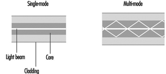
Single-mode fibre is primarily used for telephony, cable television applications and campus backbones. Multi-mode fibre is commonly used for data communications and in premise networks.
Optical fibre manufacturing
Special materials and processes are required to manufacture optical fibres that meet the basic design criteria: (1) a core with a high refractive index and cladding with a low refractive index, (2) a low signal attenuation or power loss, and (3) a low dispersion or broadening of the light beam.
High-purity silica glass with other glass materials (i.e., heavy-metal fluoride glasses, chalcogenide glasses) are the primary materials currently used to manufacture optical fibres. Polycrystalline materials, single-crystal materials, hollow waveguides and polymeric plastic materials are also used. Raw materials must be relatively pure with very low concentrations of transition metals and hydroxyl-forming groups (below the parts per billion level). Processing methods must shield the forming glass from impurities in the manufacturing environment.
Optical fibres are manufactured by using a non-conventional vapour phase preparation of a glass preform which is then drawn into fibre. Volatile silica compounds are converted to SiO2 by flame hydrolysis, chemical vapour deposition (CVD) or high-temperature oxidation. Other dopants are then added to the glass to change the glass properties. Variations in the process of vapour deposition start with the same material but differ in the method used to convert this material to silica.
One of the following vapour phase deposition methods is used to manufacture silica-based optical fibres: (1) modified chemical vapour deposition (MCVD), (2) plasma chemical vapour deposition (PCVD), (3) outside vapour deposition (OVD), and (4) vapour phase axial deposition (VAD) (see figure 2). Silicon tetrachloride (SiCI4), germanium tetrachloride (GeCI4) or other volatile liquid halides convert to gas when heated slightly due to their high vapour pressures. Gaseous halide is delivered to a reaction zone and converted to glass particles (see also the chapter Microelectronics and semiconductors.)
Figure 2. Optic fibre manufacturing flow chart

MCVD and PCVD processes. A high-quality fused silica tube is attached to a glass working lathe fitted with a hydrogen/oxygen torch that traverses its length. A halide material supply is attached to one end of the glass tube and a scrubber to the opposite end to remove excess halide material. The surface of the glass tube is first cleaned by fire polishing as the torch traverses the tube’s length. Various reagents are added in the vapour system depending on the product being manufactured. A chemical reaction occurs as the halides pass through the section of the tube being heated. The halides convert to silica “soot” particles that deposit on the inner glass tube wall downstream from the torch. Deposited particles are sintered into the glass layer. The PCVD process is similar to MCVD except that the halides are supplied by a bubbler system, and microwaves are used instead of a torch to convert the halide material to glass.
OVD and VAD processes. In the first stage of the fibre manufacturing process, the core and cladding glasses are vapour deposited around a rotating target rod to form a “soot” preform. The core material is deposited first, followed by the cladding. The entire preform must be extremely pure, since both the core and cladding are vapour deposited. Fibre geometry is determined during the laydown phase of manufacturing. After the target rod is removed, the preform is placed in a furnace, where it is consolidated into a solid, clear glass and the centre hole is closed. Gas is passed through the preform to remove residual moisture which adversely affects the attenuation of the fibre (loss of optical signal as light transmits along the fibre axis). Preforms are then washed with hydrofluoric acid to ensure the purity of the glass and to remove contaminants.
The consolidated glass preform is placed in a draw tower to form a continuous strand of glass fibre. First the preform is loaded into the top of a draw furnace. Next, the tip of the preform is heated and a piece of molten glass begins to fall. As this piece is drawn (pulled), it passes through an inline diameter monitor to assure the fibre meets an exact specified diameter (usually measured in microns.) The fibre’s cladding diameter must conform with exact specifications in order to keep signal loss at connections low. The outer cladding diameter is used as a guide to align fibre cores during end use. The cores must line up so light transfer occurs efficiently.
Acrylate polymer or other coatings are applied and cured with ultraviolet lamps. The coatings are intended to protect the optical fibre from the environment during end use. The optical fibres are tested to assure conformance with manufacturing standards for strength, attenuation and geometry. Specific lengths of fibre are wound onto reels per customer specifications.
A number of potential hazards are encountered during optical fibre manufacturing. These include: (1) exposure to hydrofluoric acid (when cleaning glass preforms), (2) radiant energy and heat stress associated with working environments near lathes and vapour deposition processes, (3) direct contact with hot surfaces or molten material (glass preforms), (4) exposure to acrylate polymer coatings (skin sensitizers), (5) skin punctures and lacerations during fibre handling and (6) a variety of physical hazards previously described.