- You are here:
-
Home

- Part XII. Chemical Industries
Children categories

77. Chemical Processing (8)

77. Chemical Processing
Chapter Editors: Jeanne Mager Stellman and Michael McCann
Table of Contents
Tables and Figures
Chemical Industry
L. De Boer
Developing a Process Safety Management Programme
Richard S. Kraus
Major Unit Operations and Processes: An Overview
Sydney Lipton
Examples of Chemical Processing Operations
Chlorine and Caustic Production
The Chlorine Institute, Inc.
Paint and Coating Manufacture
Michael McCann
Plastics Industry
P.K. Law and T.J. Britton
Biotechnology Industry
Susan B. Lee and Linda B. Wolfe
Pyrotechnics Industry
J. Kroeger
Tables
Click a link below to view table in article context.
1. Chemical industry employment in selected countries
2. Some general site selection factors
3. Plant siting safety considerations
4. Facilities generally separated in overall plant layouts
5. General considerations in a process unit layout
6. Steps for limiting inventory
7. Tank separation & location considerations
8. Pumps in the chemicals process industry
9. Potential explosion sources in equipment
10. Volatile products of the decomposition of plastics
11. Microorganisms of industrial importance
12. Raw materials used in the manufacture of pyrotechnics
Figures
Point to a thumbnail to see figure caption, click to see figure in article context.
|
|


78. Oil and Natural Gas (1)
78. Oil and Natural Gas
Chapter Editor: Richard S. Kraus
Table of Contents
Petroleum Refining Process
Richard S. Kraus
Tables
Click a link below to view table in article context.
1. Summary of the history of refining processing
2. Principal products of crude oil refining
3. Overview of petroleum refining processes
Figures
Point to a thumbnail to see figure caption, click to see figure in article context.


79. Pharmaceutical Industry (2)
79. Pharmaceutical Industry
Chapter Editor: Keith D. Tait
Table of Contents
Tables and Figures
Pharmaceutical Industry
Keith D. Tait
Case Study: Effects of Synthetic Oestrogens on Pharmaceutical Workers: A United States Example
Dennis D. Zaebst
Tables
Click a link below to view table in article context.
1. Major categories of pharmaceutical agents
2. Solvents used in the pharmaceutical industry
Figures
Point to a thumbnail to see figure caption, click to see figure in article context.


80. Rubber Industry (12)
80. Rubber Industry
Chapter Editors: Louis S. Beliczky and John Fajen
Table of Contents
Tables and Figures
General Profile
Louis S. Beliczky and John Fajen
Rubber Tree Cultivation
Alan Echt
Tyre Manufacturing
James S. Frederick
Non-Tyre Industrial Products
Ray C. Woodcock
Case Study: Salt Bath Vulcaization
Beth Donovan Reh
1,3-Butadiene
Ronald L. Melnick
Engineering Controls
Ray C. Woodcock
Safety
James R. Townhill
Epidemiological Studies
Robert Harris
Rubber Contact Dermatitis and Latex Allergy
James S. Taylor and Yung Hian Leow
Ergonomics
William S. Marras
Environmental and Public Health Issues
Thomas Rhodarmer
Tables
Click a link below to view table in article context.
1. Some important rubber polymers
2. Worldwide rubber consumption for 1993
Figures
Point to a thumbnail to see figure caption, click to see figure in article context.
|
|


Chemical Industry
Adapted from 3rd edition, Encyclopaedia of Occupational Health and Safety.
The business of the chemical industry is to change the chemical structure of natural materials in order to derive products of value to other industries or in daily life. Chemicals are produced from these raw materials-principally minerals, metals and hydrocarbons-in a series of processing steps. Further treatment, such as mixing and blending, is often required to convert them into end-products (e.g., paints, adhesives, medicines and cosmetics). Thus the chemical industry covers a much wider field than what is usually called “chemicals” since it also includes such products as artificial fibres, resins, soaps, paints, photographic films and more.
Chemicals fall into two main classes: organic and inorganic. Organic chemicals have a basic structure of carbon atoms, combined with hydrogen and other elements. Oil and gas are today the source of 90% of world organic chemical production, having largely replaced coal and vegetable and animal matter, the earlier raw materials. Inorganic chemicals are derived chiefly from mineral sources. Examples are sulphur, which is mined as such or extracted from ores, and chlorine, which is made from common salt.
The products of the chemical industry can be broadly divided into three groups, which correspond to the principal steps in manufacture: base chemicals (organic and inorganic) are normally manufactured on a large scale and are normally converted to other chemicals; intermediates are derived from base chemicals. Most intermediates require further processing in the chemical industry, but some, such as solvents, are used as they are; finished chemical products are made by further chemical processing. Some of these (drugs, cosmetics, soaps) are consumed as such; others, such as fibres, plastics, dyes and pigments, are processed still further.
The main sectors of the chemical industry are as follows:
- basic inorganics: acids, alkalis and salts, mainly used elsewhere in industry and industrial gases, such as oxygen, nitrogen and acetylene
- basic organics: feedstocks for plastics, resins, synthetic rubbers, and synthetic fibres; solvents and detergent raw materials; dyestuffs and pigments
- fertilizers and pesticides (including herbicides, fungicides and insecticides)
- plastics, resins, synthetic rubbers, cellulosic and synthetic fibres
- pharmaceuticals (drugs and medicines)
- paints, varnishes and lacquers
- soaps, detergents, cleaning preparations, perfumes, cosmetics and other toiletries
- miscellaneous chemicals, such as polishes, explosives, adhesives, inks, photographic film and chemicals
In the International Standard Industrial Classification of All Economic Activities (ISIC) system, used by the United Nations to classify economic activity into ten major divisions, the chemical industry is classified as Division 35, one of the nine subdivisions of Major Division 3: Manufacturing. Division 35 is further subdivided into industrial chemicals (351), other chemicals (352), petroleum refineries (353), miscellaneous coal and petroleum products, e.g., asphalt (354), rubber products including tyres (355) and plastics processing (356).
In reporting chemical industry statistics each country normally uses its own classification system, and this can be misleading. Thus comparison between countries of total chemical industry performance cannot be based on national sources. However, international bodies like the Organization for Economic Cooperation and Development (OECD) and the United Nations normally supply data on the ISIC basis, though with a delay of about two years.
Trade statistics are published internationally under the Standard International Trade Classification (SITC), which differs from the ISIC system. Trade statistics by individual countries nearly always refer to SITC section 5, which covers about 90% of total chemicals reported in the ISIC system.
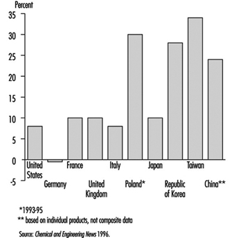
The chemical industry has grown much more rapidly in the half century than industry as a whole. Although there was an economic depression in the world’s chemical industry in the early 1990s, chemical production increased in the mid-1990s. The biggest area of growth of chemical production has been in Southeast Asia. Figure 1 shows the percentage change in chemical production for 1992-95 for selected countries.
Figure 1.Change in chemical production for selected countries, 1992-95
Much of the chemical industry is highly capital-intensive and is also strongly dependent on research and development (e.g., pharmaceuticals). The combined result of these two factors is that the industry employs an abnormally low number of unskilled manual workers for its size, in comparison with manufacturing industry in general. Total employment in the industry rose slightly during the period of rapid growth prior to 1970, but since then the drive for increased productivity has resulted in a decline in employment in the chemical industry in most developed countries. Table 1 shows chemical industry employment in the United States and several European countries for 1995.
Table 1. Chemical industry employment in selected countries (1995)
|
Country |
Employment |
|
United States |
1, 045,000 |
|
Germany |
538,000 |
|
France |
248,000 |
|
United Kingdom |
236,000 |
|
Italy |
191,000 |
|
Poland |
140,000 |
|
Spain |
122,000 |
Source: Chemical and Engineering News 1996.
Chlorine and Caustic Production
The Chlorine Institute, Inc.
Electrolysis of salt brines produces chlorine and caustic. Sodium chloride (NaCl) is the primary salt used; it yields caustic soda (NaOH). However, the use of potassium chloride (KCl) produces caustic potash (KOH).
2 NaCl + 2 H2O → Cl2↑+ 2 NaOH + H2↑
salt + water → chlorine (gas) + caustic + hydrogen (gas)
Currently the diaphragm cell process is in greatest use for the commercial production of chlorine followed by the mercury cell process and then the membrane cell process. Due to economic, environmental and product quality issues, manufacturers now prefer the membrane cell process for new production facilities.
The Diaphragm Cell Process
A diaphragm cell (see figure 1) is fed saturated salt brine into a compartment containing a titanium anode coated with salts of ruthenium and other metals. A plastic cell head collects the hot, wet chlorine gas produced at this anode. Suction by a compressor then draws the chlorine into a collection header for further processing consisting of cooling, drying and compression. Water and unreacted brine percolate through a porous diaphragm separator into the cathode compartment where water reacts at a steel cathode to produce sodium hydroxide (caustic soda) and hydrogen. The diaphragm keeps the chlorine produced at the anode from the sodium hydroxide and hydrogen produced at the cathode. If these products combine, the result is sodium hypochlorite (bleach) or sodium chlorate. Commercial producers of sodium chlorate use cells that do not have separators. The most common diaphragm is a composite of asbestos and a fluorocarbon polymer. Modern diaphragm cell plants do not have the health or environmental problems historically associated with the use of asbestos diaphragms. Some plants do employ non-asbestos diaphragms, which are now commercially available. The diaphragm cell process produces a weak sodium hydroxide solution containing unreacted salt. An additional evaporation process concentrates the caustic and removes most of the salt to make a caustic of commercial quality.
Figure 1. Types of chloralkali cell processes
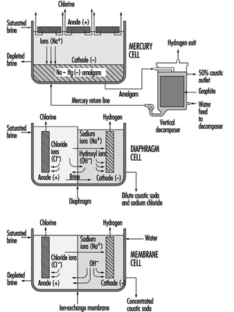
The Mercury Cell Process
A mercury cell actually consists of two electrochemical cells. The reaction in the first cell at the anode is:
2 Cl– → C12 + 2 e–
chloride → chlorine + electrons
The reaction in the first cell at the cathode is:
Na+ + Hg + e– → Na · Hg
sodium ion + mercury + electrons → sodium amalgam
Salt brine flows in an inclined steel trough with rubber-lined sides (see figure 4) Mercury, the cathode, flows under the brine. Anodes of coated titanium are suspended in the brine for the production of chlorine, which exits the cell to a collection and processing system. Sodium is electrolyzed in the cell and leaves the first cell amalgamated with the mercury. This amalgam flows into a second electrochemical cell called the decomposer. The decomposer is a cell with graphite as a cathode and the amalgam as the anode.
The reaction in the decomposer is:
2 Na•Hg + 2 H2O → 2 NaOH + 2 Hg + H2 ↑
The mercury cell process produces commercial (50%) NaOH directly from the cell.
The Membrane Cell Process
The electrochemical reactions in a membrane cell are the same as in the diaphragm cell. A cation-exchange membrane is used in place of the porous diaphragm (see figure 1). This membrane prevents the migration of chloride ions into the catholyte, thereby producing essentially salt free 30 to 35% caustic directly from the cell. The elimination of the need to remove salt makes the evaporation of the caustic to commercial 50% strength simpler, and it requires less investment and energy. Expensive nickel is used as the cathode in the membrane cell due to the stronger caustic.
Safety and Health Hazards
At ordinary temperatures, dry chlorine, either liquid or gas, does not corrode steel. Wet chlorine is highly corrosive because it forms hydrochloric and hypochlorous acids. Precautions should be taken to keep chlorine and chlorine equipment dry. Piping, valves and containers should be closed or capped when not in use to keep out atmospheric moisture. If water is used on a chlorine leak the resulting corrosive conditions will make the leak worse.
The volume of liquid chlorine increases with temperature. Precautions should be taken to avoid hydrostatic rupture of piping, vessels, containers or other equipment filled with liquid chlorine.
Hydrogen is a co-product of all chlorine manufactured by the electrolysis of aqueous brine solutions. Within a known concentration range, mixtures of chlorine and hydrogen are flammable and potentially explosive. The reaction of chlorine and hydrogen can be initiated by direct sunlight, other sources of ultraviolet light, static electricity or sharp impact.
Small quantities of nitrogen trichloride, an unstable and highly explosive compound, can be produced in the manufacturing of chlorine. When liquid chlorine containing nitrogen trichloride is evaporated, the nitrogen trichloride may reach hazardous concentrations in the remaining liquid chlorine.
Chlorine can react, at times explosively, with a number of organic materials such as oil and grease from sources such as air compressors, valves, pumps and oil-diaphragm instrumentation, as well as wood and rags from maintenance work.
As soon as there is any indication of a chlorine release, immediate steps must be taken to correct the condition. Chlorine leaks always get worse if they are not promptly corrected. When a chlorine leak occurs, authorized, trained personnel equipped with respiratory and other appropriate personal protective equipment (PPE) should investigate and take proper action. Personnel should not enter into atmospheres containing concentrations of chlorine in excess of the immediately dangerous to life and health (IDLH) concentration (10 ppm) without appropriate PPE and back-up personnel. Unnecessary personnel should be kept away and the hazard area should be isolated. Persons potentially affected by a chlorine release should be evacuated or sheltered in place as circumstances warrant.
Area chlorine monitors and wind direction indicators can supply timely information (e.g., escape routes) to help determine whether personnel are to be evacuated or sheltered in place.
When evacuation is utilized, potentially exposed persons should move to a point upwind of the leak. Because chlorine is heavier than air, higher elevations are preferable. To escape in the shortest time, persons already in a contaminated area should move crosswind.
When inside a building and sheltering in place is selected, shelter can be achieved by closing all windows, doors and other openings, and turning off air conditioners and air intake systems. Personnel should move to the side of the building furthest from the release.
Care must be taken not to position personnel without an escape route. A safe position may be made hazardous by a change in wind direction. New leaks may occur or the existing leak may get larger.
If fire is present or imminent, chlorine containers and equipment should be moved away from the fire, if possible. If a non-leaking container or equipment cannot be moved, it should be kept cool by applying water. Water should not be used directly on a chlorine leak. Chlorine and water react forming acids and the leak quickly will get worse. However, where several containers are involved and some are leaking, it may be prudent to use a water spray to help prevent overpressure of the non-leaking containers.
Whenever containers have been exposed to flames, cooling water should be applied until well after the fire is out and the containers are cooled. Containers exposed to fire should be isolated and the supplier should be contacted as soon as possible.
Sodium hydroxide solutions are corrosive, especially when concentrated. Workers at risk for exposure to spills and leaks should wear gloves, face shield and goggles and other protective clothing.
Acknowledgements: Dr. R.G. Smerko is acknowledged for making available the resources of the Chlorine Institute, Inc.
Developing a Process Safety Management Programme
Whenever there are processes that use temperature and pressure to change the molecular structure or create new products from chemicals, the possibility exists for fires, explosions or releases of flammable or toxic liquids, vapours, gases or process chemicals. The control of these undesired events requires a special science called process safety management. The terms process safety and process safety management are most commonly used to describe the protection of employees, the public and the environment from the consequences of undesirable major incidents involving flammable liquids and highly hazardous materials. According to the United States Chemical Manufacturers’ Association (CMA), “process safety is the control of hazards which are caused by maloperation or malfunction of the processes used to convert raw materials into finished products, which may lead to the unplanned release of hazardous material” (CMA 1985).
Industry and labour process safety involvement
Process safety technology has played an important role in the chemical processing industries so that handling flammable and combustible liquids and gases could proceed without undesirable consequences. During the 1980s, the oil and gas industries, for example, recognized that process safety technology alone, without process safety management, would not prevent catastrophic incidents. With this in mind, a number of industry associations, such as, in the United States, the Center for Chemical Process Safety (CCPS), the American Petroleum Institute (API) and the Chemical Manufacturers' Association (CMA), initiated programmes to develop and provide process safety management guidelines for use by their members. As stated by the CCPS, "The evolution of process safety from a purely technical issue to one that demanded management approaches was essential to continued process safety improvement".
The CCPS was formed in 1985 to promote the improvement of process safety management techniques among those who store, handle, process and use hazardous chemicals and materials. In 1988, the Chemical Manufacturer's Association (CMA) initiated its Responsible Care® programme outlining each member company's commitment to environmental, health and safety responsibility in managing chemicals.
In 1990, the API initiated an industry-wide programme entitled, STEP-Strategies for Today's Environmental Partnership, with the intention of improving the oil and gas industry's environmental, health and safety performance. One of the seven strategic elements of the STEP programme covers petroleum operating and process safety. The following documents are examples of some of the materials developed as a result of the STEP programme which provide guidance to the oil and gas industry to help prevent the occurrence or minimize the consequences of catastrophic releases of flammable liquids and vapours or hazardous process materials:
- Management of Process Hazards (RP 750)
RP 750 covers the management of hydrocarbon process hazards in design, construction, start-up, operations, inspection, maintenance and facility modifications. It applies specifically to refineries, petro-chemical plants and major processing facilities that use, produce, process or store flammable liquids and toxic processing chemicals in quantities above certain hazardous amounts (as defined therein).
- Management of Hazards Associated with Location of Process Plant Buildings (RP 752)
RP 752, co-developed by API and CMA, is intended to help identify process plant buildings of concern, understand the potential hazards related to their location within the process facility and manage the risk of fire, explosion and toxic releases.
- Management Practices, Self-assessment Process, and Resource Materials (RP 9000)
RP 9000 provides resource materials and self assessment methodology to measure progress in implementing process safety management elements.
Examples of other organizations which have developed materials and programmes providing guidance covering chemical process safety management include, but are not limited to, the following:
- Organizations Resource Counselors' (ORC) report, Process Hazards Management of Substances with Catastrophic Potential
- National Petroleum Refiners Association (NPRA), BEST (Building Environmental Stewardship Tools) programme
- International Labour Organization (ILO), Code of Practice on the Prevention of Major Accident Hazards
- International Chamber of Commerce (ICC), Charter for Sustainable Development.cmp01ce.doc
The process design and technology, changes in the process, materials and changes in materials, operations and maintenance practices and procedures, training, emergency preparedness and other elements affecting the process must all be considered in the systematic identification and evaluation of hazards so as to determine whether or not they have the potential to lead to a catastrophe in the workplace and surrounding community.
Beginning in the early 1980s, a number of serious major incidents occurred in the petroleum and chemical industries involving highly hazardous materials, which resulted in considerable numbers of fatalities and injuries and significant property losses. These incidents provided the impetus for government agencies, labour organizations and industry associations throughout the world to develop and implement codes, regulations, procedures and safe work practices directed toward the elimination or mitigation of these undesirable events, through the application of the principles of process safety management. They are discussed more fully in the Disasters, natural and technological chapter and elsewhere in this Encyclopaedia.
In response to public concern over the potential hazards of chemicals, governments and regulatory agencies throughout the world initiated programmes which required manufacturers and users to identify hazardous materials in the workplace and inform employees and consumers of the hazards presented by their manufacture, use, storage and handling. These programmes, which covered emergency preparedness and response, hazard recognition, product knowledge, control of hazardous chemicals and reporting of toxic releases, included hydrocarbon processing.
Process Safety Management Requirements
Process safety management is an integral part of the overall chemical processing facility safety programme. An effective process safety management programme requires the leadership, support and involvement of top management, facility management, supervisors, employees, contractors and contractor employees.
Components to be considered when developing a process safety management programme include:
- Interdependent continuity of operations, systems and organization
- Management of information. The process safety management programme relies upon providing availability and access to good records and documentation.
- Control of process quality, deviations and exceptions and alternate methods
- Management and supervisory accessibility and communications. Because process safety management is the basis for all safety efforts within the facility, managerial, supervisory and employee responsibility and accountability should be clearly delineated, communicated and understood in order for the programme to work.
- Goals and objectives, compliance audits and performance measurement. Prior to implementation, it is important to establish both long-term and short-term goals and objectives for each of the elements of the process safety management programme.
Elements of the Process Safety Management Programme
All chemical facility process safety management programmes cover the same basic requirements, although the number of programme elements may vary depending on the criteria used. Regardless which government, company or association source document is used as a guide, there are a number of basic requirements which should be included in every chemical process safety management programme:
- process safety information
- employee involvement
- process hazard analysis
- management of change
- operating procedures
- safe work practices and permits
- employee information and training
- contractor personnel
- pre-startup safety reviews
- design quality assurance
- maintenance and mechanical integrity
- emergency response
- periodic safety audits
- process incident investigation
- standards and regulations
- trade secrets.
Process safety information
Process safety information is used by the process industry to define critical processes, materials and equipment. Process safety information includes all available written information concerning process technology, process equipment, raw materials and products and chemical hazards before conducting a process hazard analysis. Other critical process safety information is documentation relating to capital project reviews and design basis criteria.
Chemical information includes not only the chemical and physical properties, reactivity and corrosive data and thermal and chemical stability of chemicals such as hydrocarbons and highly hazardous materials in the process, but also the hazardous effects of inadvertently mixing different incompatible materials. Chemical information also includes that which may be needed to conduct environmental hazard assessments of toxic and flammable releases and permissible exposure limits.
Process technology information includes block flow diagrams and/ or simple process flow diagrams as well as descriptions of the chemistry of each specific process with the safe upper and lower limits for temperatures, pressures, flows, compositions and, where available, process design material and energy balances. The consequences of deviations in the process and materials, including their effect on employee safety and health, are also determined. Whenever processes or materials are changed, the information is updated and re-evaluated in accordance with the facility’s management of change system.
Process equipment and mechanical design information includes documentation covering the design codes employed and whether or not equipment complies with recognized engineering practices. A determination is made as to whether existing equipment which was designed and constructed in accordance with codes, standards and practices no longer in general use is maintained, operated, inspected and tested to assure continued safe operation. Information on materials of construction, piping and instrument diagrams, relief system design, electrical classification, ventilation design and safety systems is updated and re-evaluated when changes occur.
Employee involvement
Process safety management programmes should include employee participation in the development and conduct of process safety analyses and other elements of the programme. Access to process safety information, incident investigation reports and process hazard analyses is usually provided to all employees and contractor employees working in the area. Most industrialized nations require that workers be systematically instructed in the identification, nature and safe-handling of all chemicals to which they may be exposed.
Process hazard analysis
After the process safety information is compiled, a thorough and systematic multi-disciplinary process hazard analysis, appropriate to the complexity of the process, is conducted in order to identify, evaluate and control the hazards of the process. Persons performing the process hazard analysis should be knowledgeable and experienced in relevant chemistry, engineering and process operations. Each analysis team normally includes at least one person who is thoroughly familiar with the process being analysed and one person who is competent in the hazard analysis methodology being used.
The priority order used to determine where within the facility to begin conducting process hazard analyses is based on the following criteria:
- extent and nature of the process hazards
- number of potentially affected workers
- operating and incident history of the process
- age of the process.
A number of methods for conducting process safety analyses are used in the chemical industry.
The “what if?” method asks a series of questions to review potential hazard scenarios and possible consequences and is most often used when examining proposed modifications or changes to the process, materials, equipment or facility.
The “checklist” method is similar to the “what if?” method, except that a previously developed checklist is used which is specific to the operation, materials, process and equipment. This method is useful when conducting pre-startup reviews upon completion of initial construction or following major turnarounds or additions to the process unit. A combination of the “what if?” and “checklist” methods is often used when analysing units that are identical in construction, materials, equipment and process.
The hazard and operability (HAZOP) study method is commonly used in the chemical and petroleum industries. It involves a multi-disciplinary team, guided by an experienced leader. The team uses specific guide words, such as “no”, “increase”, “decrease” and “reverse”, which are systematically applied to identify the consequences of deviations from design intent for the processes, equipment and operations being analysed.
Fault tree/event tree analyses are similar, formal deductive techniques used to estimate the quantitative likelihood of an event occurring. Fault tree analysis works backward from a defined incident to identify and display the combination of operational errors and/ or equipment failures which were involved in the incident. Event tree analysis, which is the reverse of fault tree analysis, works forwards from specific events, or sequences of events, in order to pinpoint those that could result in hazards, and thereby calculate the likelihood of an event’s sequence occurring.
The failure mode and effects analysis method tabulates each process system or unit of equipment with its failure modes, the effect of each potential failure on the system or unit and how critical each failure could be to the integrity of the system. The failure modes are then ranked in importance to determine which is most likely to cause a serious incident.
No matter which method is used, all chemical process hazard analyses consider the following:
- process location, siting and hazards of the process
- identification of any prior incident or near miss with potential catastrophic consequences
- engineering and administrative controls applicable to the hazards
- interrelationships of controls and appropriate application of detection methodology to provide early warnings
- consequences of human factors, facility siting and failure of the controls
- consequences of safety and health effects on workers within areas of potential failure.
Management of change
Chemical process facilities should develop and implement programmes which provide for the revision of process safety information, procedures and practices as changes occur. Such programmes include a system of management authorization and written documentation for changes to materials, chemicals, technology, equipment, procedures, personnel and facilities that affect each process.
Management of change programmes in the chemical industry, for example, include the following areas:
- change of hydrocarbon process technology
- changes in facility, equipment or materials (e.g., catalysts or additives)
- management of change personnel and organizational and personnel changes
- temporary changes, variances and permanent changes
- enhancement of process safety knowledge, including:
- technical basis for proposed change
- impact of change on safety, health and environment
- modifications to operating procedures and safe work practices
- modifications required to other processes
- time required for the change
- authorization requirements for the proposed change
- updating documentation relating to process information, operating procedures and safety practices
- required training or education due to change
- management of subtle change (anything which is not replacement in kind)
- non-routine changes.
The management of change system includes informing employees involved in the process and maintenance and contractor personnel whose tasks would be affected by any changes of the changes and providing updated operating procedures, process safety information, safe work practices and training as needed, prior to the startup of the process or affected part of the process.
Operating procedures
Chemical processing facilities must develop and provide operating instructions and detailed procedures to workers. Operating instructions should be regularly reviewed for completeness and accuracy (and updated or amended as changes occur) and cover the process unit’s operating limits, including the following three areas:
- consequences of deviation
- steps to avoid or correct deviation
- functions of safety systems related to operating limits.
Workers involved in the process have access to operating instructions covering the following areas:
- initial startup (startup after turnarounds, emergencies and temporary operations)
- normal startup (normal and temporary operations and normal shutdown)
- emergency operations and emergency shutdown
- conditions under which emergency shutdown is required and assignment of shutdown responsibilities to qualified operators
- non-routine work
- operator-process and operator-equipment interface
- administrative controls vs. automated controls.
Safe work practices
Chemical process facilities should implement hot-work and safe work permit and work order programmes to control work conducted in or near process areas. Supervisors, employees and contractor personnel must be familiar with the requirements of the various permit programmes, including permit issuance and expiration and appropriate safety, materials handling and fire protection and prevention measures.
The types of work included in typical chemical facility permit programmes include the following:
- hot work (welding, hot tapping, internal combustion engines, etc.)
- lockout/tagout of electrical, mechanical, pneumatic energy and pressure
- confined-space entry and use of inert gas
- venting, opening and cleaning process vessels, tanks, equipment and lines
- control of entry into process areas by non-assigned personnel.
Chemical facilities should develop and implement safe work practices to control potential hazards during process operations, covering the following areas of concern:
- properties and hazards of materials, catalysts and chemicals used in the process
- engineering, administrative and personal protection controls to prevent exposures
- measures to be taken in event of physical contact or exposure with hazardous chemical
- quality control of raw materials, catalysts and inventory control of hazardous chemicals
- safety and protection system (interlock, suppression, detection, etc.) functions
- special or unique hazards in the workplace.
Employee information and training
Chemical process facilities should use formal process safety training programmes to train and educate incumbent, reassigned and new supervisors and workers. The training provided for chemical process operating and maintenance supervisors and workers should cover the following areas:
- required skills, knowledge and qualifications of process employees
- selection and development of process related training programmes
- measuring and documenting employee performance and effectiveness
- design of process operating and maintenance procedures
- overview of process operations and process hazards
- availability and suitability of materials and spare parts for the processes in which they are to be used
- process start-up, operating, shut-down and emergency procedures
- safety and health hazards related to the process, catalysts and materials
- facility and process area safe work practices and procedures.
Contractor personnel
Contractors are often employed in chemical processing facilities. The facilities must institute procedures to assure that contractor personnel performing maintenance, repair, turnaround, major renovation or specialty work are fully aware of the hazards, materials, processes, operating and safety procedures and equipment in the area. Periodic evaluations of performance are made to assure that contractor personnel are trained, qualified, follow all safety rules and procedures and are informed and aware of the following:
- potential fire, explosion and toxic release hazards related to their work
- plant safety procedures and contractor safe work practices
- emergency plan and contractor personnel actions
- controls for contractor personnel entry, exit and presence in process areas.
Pre-startup safety reviews
Pre-startup process safety reviews are conducted in chemical plants prior to startup of new process facilities and introduction of new hazardous materials or chemicals into facilities, following a major turnaround and where facilities have had significant process modifications.
The pre-startup safety reviews assure the following have been accomplished:
- construction, materials and equipment are verified as in accordance with design criteria
- process systems and hardware, including computer control logic, have been inspected, tested and certified
- alarms and instruments are inspected, tested and certified
- relief and safety devices and signal systems are inspected, tested and certified
- fire protection and prevention systems are inspected, tested and certified
- safety, fire prevention and emergency response procedures are developed, reviewed, in place and are appropriate and adequate
- startup procedures are in place and proper actions have been taken
- a process hazard analysis has been performed and all recommendations addressed, implemented or resolved and actions documented
- all required initial and/ or refresher operator and maintenance personnel training, including emergency response, process hazards and health hazards, is completed
- all operating procedures (normal and upset), operating manuals, equipment procedures and maintenance procedures are completed and in place
- management of change requirements for new processes and modifications to existing processes have been met.
Design Quality Assurances
When new processes or major changes to existing processes are undertaken, a series of process safety design reviews are normally conducted before and during construction (prior to the pre-startup review). The design control review, conducted just before plans and specifications are issued as “final design drawings”, covers the following areas:
- plot plan, siting, spacing, electrical classification and drainage
- hazards analysis and process chemistry design
- project management requirements and qualifications
- process equipment and mechanical equipment design and integrity
- piping and instrument drawings
- reliability engineering, alarms, interlocks, reliefs and safety devices
- materials of construction and compatibility.
Another review is normally conducted just prior to the start of construction covering the following:
- demolition and excavation procedures
- control of raw materials
- control of construction personnel and equipment on facility and site
- fabrication, construction and installation procedures and inspection.
One or more reviews are usually conducted during the course of construction or modification to assure the following areas are in accordance with design specifications and facility requirements:
- materials of construction provided and used as specified
- proper assembly and welding techniques, inspections, verifications and certifications
- chemical and occupational health hazards considered during construction
- physical, mechanical and operational safety hazards considered during construction and facility permit and safety practices followed
- interim protective and emergency response systems provided and working.
Maintenance and mechanical integrity
Process facilities have programmes to maintain ongoing integrity of process-related equipment, including periodic inspection, testing, performance maintenance, corrective action and quality assurance. The programmes are intended to assure that mechanical integrity of equipment and materials is reviewed and certified and deficiencies corrected prior to startup, or provisions made for appropriate safety measures.
Mechanical integrity programmes cover the following equipment and systems:
- pressure vessels and storage tanks
- emergency shutdown and fire protection systems
- process safeguards such as relief and vent systems and devices, controls, interlocks, sensors and alarms
- pumps and piping systems (including components such as valves)
- quality assurance, materials of construction and reliability engineering
- maintenance and preventive maintenance programmes.
Mechanical integrity programmes also cover inspection and testing of maintenance materials, spare parts and equipment to assure proper installation and adequacy for the process application involved. The acceptance criteria and frequency of inspections and tests should conform with manufacturers’ recommendations, good engineering practices, regulatory requirements, industry practices, facility policies or prior experience.
Emergency Response
Emergency preparedness and response programmes are developed to cover an entire process facility and to provide for hazard identification and assessment of potential process hazards. These programmes include training and educating employees and contractor employees in emergency notification, response and evacuation procedures.
A typical process facility emergency preparedness programme complies with applicable company and regulatory requirements and includes the following:
- distinctive employee and/ or community alarm or notification system
- preferred method of internal reporting of fires, spills, releases and emergencies
- requirements for reporting process-related incidents to appropriate government agencies
- emergency shutdown, evacuation, procedures to account for personnel, emergency escape procedures, vehicle and equipment removal and route assignments
- emergency response and rescue procedures, duties and capabilities including employees, public safety, contractors and mutual aid organizations
- procedures for handling small spills or releases of hazardous chemicals
- procedures for providing and safeguarding emergency power and utilities
- business continuation plans, personnel and equipment sources
- document and record preservation, site security, cleanup, salvage and restoration.
Periodic safety audits
Many process facilities use self-evaluation process safety management audits to measure facility performance and assure compliance with internal and external (regulatory, company and industry) process safety requirements. The two basic principles of conducting self evaluation audits are: gathering all of the relevant documentation covering process safety management requirements at a specific facility and determining the programme’s implementation and effectiveness by following up on their application in one or more selected processes. A report of the audit findings and recommendations is developed and facility management maintains documentation which notes how deficiencies had been corrected or mitigated, and if not, reasons why no corrective action had been taken.
Compliance audit programmes in hydrocarbon process facilities cover the following areas:
- establishment of goals, schedule and methods of verification of findings prior to the audit
- determination of the methodology (or format) to be used in conducting the audit, and develop appropriate checklists or audit report forms
- readiness to certify compliance with government, industry and company requirements
- assignment of knowledgeable audit teams (internal and/ or external expertise)
- prompt responses to all findings and recommendations and documentation of actions taken
- maintenance of a copy of at least the most recent compliance audit report on file.
Facility and process unit specific checklists are often developed for use when conducting process safety audits which cover the following items:
- orientation and process safety management programme overview
- preliminary walk-around through the refinery or gas processing facility
- process facility documentation review
- “prior incidents” and near misses (in the process facility or specific unit)
- determination and review of selected process units to be audited
- process unit construction (initial and subsequent modifications)
- process unit chemistry hazards (feedstocks, catalysts, process chemicals, etc.)
- process unit operations
- process unit controls, reliefs and safety systems
- process unit maintenance, repair, testing and inspection
- process unit-related training and employee involvement
- process facility management of change programme, implementation and effectiveness
- process fire protection and emergency notification and response procedures.
Because the objectives and scope of audits can vary, the compliance audit team should include at least one person knowledgeable in the process being audited, one person with applicable regulatory and standards expertise and other persons with the skills and qualifications necessary for conducting the audit. Management may decide to include one or more outside experts on the audit team due to lack of facility personnel or expertise, or because of regulatory requirements.
Process incident investigation
Process facilities have established programmes to thoroughly investigate and analyse process-related incidents and near misses, promptly address and resolve findings and recommendations and review the results with workers and contractors whose jobs are relevant to the incident findings. Incidents (or near misses) are thoroughly investigated as soon as possible by a team which includes at least one person knowledgeable in the process operation involved and others with appropriate knowledge and experience.
Standards and Regulations
Process facilities are subject to two distinct and separate forms of standards and regulations.
- External codes, standards and regulations applicable to the design, operation and protection of process facilities and employees typically include government regulations and association and industry standards and practices.
- Internal policies, guidelines and procedures, developed or adopted by the company or facility to complement external requirements and to cover processes which are distinct or unique, are reviewed periodically and changed when necessary, in accordance with the facility’s management of change system.
Trade Secrets
Process facility management should provide process information, without regard to possible trade secrets or confidentiality agreements, to persons who are:
- responsible for gathering and compiling process safety information
- conducting process hazard analyses and compliance audits
- developing maintenance, operating and safe work procedures
- involved in incident (near miss) investigations
- responsible for emergency planning and response.
Facilities typically require that persons to whom process information is made available enter into agreements not to disclose the information.
Paint and Coating Manufacture
Adapted from NIOSH 1984.
Paints and coatings include paints, varnishes, lacquers, stains, printing inks and more. Traditional paints consist of a dispersion of pigment particles in a vehicle consisting of a film-former or binder (usually an oil or resin) and a thinner (usually a volatile solvent). In addition, there can be a wide variety of fillers and other additives. A varnish is a solution of oil and natural resin in an organic solvent. Synthetic resins may also be used. Lacquers are coatings in which the film dries or hardens entirely by evaporation of the solvent.
Traditional paints were under 70% solids with the remainder being mostly solvents. Air pollution regulations limiting the amount of solvents that can be emitted into the atmosphere have resulted in the development of a wide variety of substitute paints with low or no organic solvents. These include: water-based latex paints; two-part catalysed paints (e.g., epoxy and urethane systems); high solids paints (over 70% solids), including plastisol paints consisting primarily of pigments and plasticizers; radiation-cured paints; and powder coatings.
According to the US National Institute for Occupational Safety and Health (NIOSH 1984), about 60% of paint manufacturers employed fewer than 20 workers, and only about 3% had more than 250 workers. These statistics would be expected to be representative of paint manufacturers worldwide. This indicates a predominance of small shops, most of which would not have in-house health and safety expertise.
Manufacturing Processes
In general, the manufacture of paints and other coatings is a series of unit operations using batch processes. There are few or no chemical reactions; the operations are mostly mechanical. The manufacture involves the assembling of raw materials, mixing, dispersing, thinning and adjusting, filling of containers and warehousing.
Paints
Raw materials used to manufacture paints come as liquids, solids, powders, pastes and slurries. These are manually weighed out and premixed. Agglomerated pigment particles must be reduced to the original pigment size, and the particles must be wet with the binder to ensure dispersion in the liquid matrix. This dispersion process, called grinding, is done with a variety of types of equipment, including high-speed shaft-impeller dispersers, dough mixers, ball mills, sand mills, triple roll mills, pug mills and so forth. After an initial run, which might take as long as 48 hours, resin is added to the paste and the grinding process is repeated for a shorter period. The dispersed material is then transferred by gravity to a let-down tank where additional material such as tinting compounds can be added. For water-based paints, the binder is usually added at this stage. The paste is then thinned with resin or solvent, filtered and then transferred again by gravity to the can filling area. The filling can be done manually or mechanically.
After the dispersion process, it may be necessary to clean the tanks and mills before introducing a new batch. This can involve hand and power tools, as well as alkali cleaners and solvents.
Lacquers
Lacquer production usually is carried out in enclosed equipment such as tanks or mixers in order to minimize evaporation of the solvent, which would result in deposits of a dry lacquer film on processing equipment. Otherwise, lacquer production occurs in the same manner as paint production.
Varnishes
The manufacture of oleoresinous varnishes involves cooking the oil and resin to render them more compatible, to develop high molecular weight molecules or polymers and to increase solubility in the solvent. Older plants may use portable, open kettles for the heating. The resin and oil or resin alone are added to the kettle and then heated to about 316ºC. Natural resins must be heated prior to adding the oils. The materials are poured in over the top of the kettle. During cooking, the kettles are covered with refractory exhaust hoods. After cooking, the kettles are moved to rooms where they are cooled quickly, often by water spray, and then thinner and driers are added.
Modern plants use large closed reactors with capacities of 500 to 8,000 gallons. These reactors are similar to those used in the chemical process industry. They are fitted with agitators, sight-glasses, lines to fill and empty the reactors, condensers, temperature measuring devices, heat sources and so forth.
In both older and modern plants, the thinned resin is filtered as the final step before packaging. This is normally done while the resin is still hot, usually using a filter press.
Powder coatings
Powder coatings are solventless systems based on the melting and fusion of resin and other additive particles onto surfaces of heated objects. The powder coatings may be either thermosetting or thermoplastic, and include such resins as epoxies, polyethylene, polyesters, polyvinyl chloride and acrylics.
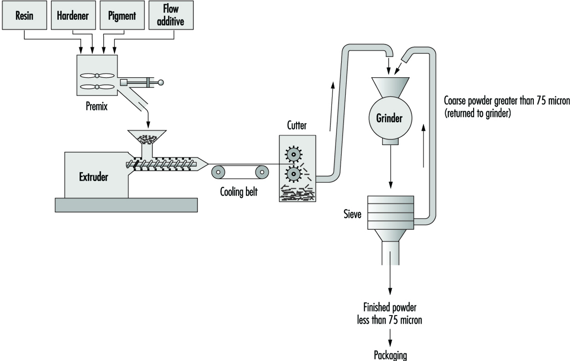
The most common method of manufacture involves dry blending of the powdered ingredients and extrusion melt-mixing (see figure 1). The dry resin or binder, pigment, filler and additives are weighed and transferred to a premixer. This process is similar to dry blending operations in rubber manufacture. After mixing, the material is placed in an extruder and heated until molten. The molten material is extruded onto a cooling conveyor belt and then transferred to a coarse granulator. The granulated material is passed through a fine grinder and then sieved to achieve the desired particle size. The powder coating is then packaged.
Figure 1. Flow chart for the manufacture of powder coatings by extrusion melt-mixing method
Hazards and Their Prevention
In general, the major hazards associated with the paint and coatings manufacture involve materials handling; toxic, flammable or explosive substances; and physical agents such as electrical shock, noise, heat and cold.
The manual handling of boxes, barrels, containers and so forth which contain the raw materials and finished products are major sources of injury due to improper lifting, slips, falls, dropping containers and so on. Precautions include engineering/ergonomic controls such as materials handling aids (rollers, jacks and platforms) and mechanical equipment (conveyors, hoists and fork-lift trucks), non-skid floors, personal protective equipment (PPE) such as safety shoes and proper training in manual lifting and other materials handling techniques.
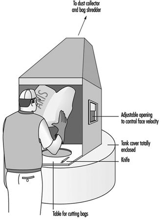
Chemical hazards include exposure to toxic dusts such as lead chromate pigment, which can occur during weighing, filling of mixer and mill hoppers, operations of unenclosed equipment, filling of powdered paint containers, cleaning of equipment and from spills of containers. The manufacture of powder coatings can result in high dust exposures. Precautions include substitution of pastes or slurries for powders; local exhaust ventilation (LEV) for opening bags of powders (see figure 2) and for processing equipment, enclosure of equipment, spill cleanup procedures and respiratory protection when needed.
Figure 2. Bag & dust control system
A wide variety of volatile solvents are used in paint and coating manufacture, including aliphatic and aromatic hydrocarbons, alcohols, ketones and so forth. The most volatile solvents are usually found in lacquers and varnishes. Exposure to solvent vapours can occur during thinning in solvent-based paint manufacture; while charging reaction vessels (especially older kettle types) in varnish manufacture; during can filling in all solvent-based coatings; and during manual cleaning of process equipment with solvents. Enclosure of equipment such as varnish reactors and lacquer mixers usually involves lower solvent exposures, except in the case of leaks. Precautions include enclosure of process equipment, LEV for thinning and can filling operations and respiratory protection and confined-space procedures for cleaning vessels.
Other health hazards include inhalation and/or skin contact with isocyanates used in manufacturing polyurethane paints and coatings; with acrylates, other monomers and photoinitiators used in the manufacture of radiation-curing coatings; with acrolein and other gaseous emissions from varnish cooking; and with curing agents and other additives in powder coatings. Precautions include enclosure, LEV, gloves and other personal protective clothing and equipment, hazardous material training and good work practices.
Flammable solvents, combustible powders (especially nitrocellulose used in lacquer production) and oils are all fire or explosion risks if ignited by a spark or high temperatures. Sources of ignition can include faulty electrical equipment, smoking, friction, open flames, static electricity and so forth. Oil-soaked rags can be a source of spontaneous combustion. Precautions include bonding and grounding containers while transferring flammable liquids, grounding of equipment such as ball mills containing combustible dusts, ventilation to keep vapour concentrations below the lower explosive limit, covering containers when not in use, removal of sources of ignition, using spark-resistant tools of non-ferrous metals around flammable or combustible materials and good housekeeping practices.
Noise hazards can be associated with the use of ball and pebble mills, high speed dispersers, vibrating screens used for filtering and so forth. Precautions include vibration isolators and other engineering controls, replacing noisy equipment, good equipment maintenance, isolation of noise source and a hearing conservation programme where excessive noise is present.
Other hazards include inadequate machine guarding, a common source of injuries around machinery. Electrical hazards are a particular problem if there is not a proper lockout/tagout programme for equipment maintenance and repair. Burns can result from hot varnish cooking vessels and spattering materials and from hot melt glues used for packages and labels.
Major Unit Operations and Processes: An Overview
This article presents information on basic process equipment, storage, plant layout and operations considerations in chemical process industries, including major items and concepts that are broadly applicable throughout the chemical industry. However, much of the equipment required in chemical processing is highly specialized and cannot be broadly generalized. More detailed information on toxicity and hazardous materials and process safety are reviewed elsewhere in this Encyclopaedia.
There are two basic categories of layout in chemical processing industries: plant layout, which covers all process units, utilities, storage areas, loading/unloading areas, buildings, shops and warehousing, and unit or process layout, which covers only equipment placement for a specific process, also termed a process block.
Plant Layout
Siting
Locating or siting an overall plant is based upon a number of general factors, as shown in table 1 (CCPS 1993). These factors vary considerably with locations, governments and economic policies. Of these various factors, safety considerations are an extremely important concern, and in some locations they can be the major factor that governs plant siting.
Table 1. Some general site selection factors
- Population density around the site
- Natural disaster occurrence (earthquake, flood, etc.)
- Prevailing winds and meteorological data
- Availability of power, steam and water
- Safety considerations
- Air, water and waste regulations and their complexity
- Accessibility to raw materials and markets
- Transportation
- Siting permits and complexity of obtaining them
- Interaction requirements in industrial developments
- Labour availability and costs
- Investment incentives
One important aspect of plant safety in siting is defining a buffer zone between a plant with hazardous processes and nearby plants, dwellings, schools, hospitals, highways, waterways and airplane corridors. Some overall safety considerations are presented in table 2. The buffer zone is important because distance tends to reduce or mitigate potential exposures from various accidents. The distance necessary to reduce toxic concentrations to acceptable levels through atmospheric interaction and the dispersion of toxic materials from an accidental release can be defined. Moreover, the time lag between a toxic release and public exposure created by a buffer zone can be used to warn the population through pre-planned emergency response programmes. Since plants have various types of facilities containing toxic materials, dispersion analyses should be conducted on the potentially hazardous systems to ensure the buffer zone is adequate in each area surrounding the plant perimeter.
Table 2. Plant siting safety considerations
- Buffer zone
- Location of other hazardous installations in vicinity
- Inventory of toxic and hazardous materials
- Adequacy of firefighting water supply
- Emergency equipment access
- Availability of emergency response support from adjacent industries and the community
- Weather extremes and prevailing winds
- Location of highways, waterways, railroad and airplane corridors
- Environmental and waste disposal restrictions during emergencies
- Draining and grade slope
- Maintenance and inspection
Fire is a potential hazard in process plants and facilities. Large fires can be a source of thermal radiation which can also be mitigated by distance. Elevated flares can also be a source of thermal radiation during an emergency or startup/shutdown operation. A flare is a device that automatically burns exhaust gases or emergency vapour releases at elevated positions or special ground locations. These should be sited away from the plant perimeter (for community protection) and an area at the flare base should be prohibited to workers. If not operated properly, liquid carryover into the flare can result in burning liquid droplets. In addition to fire, there can be explosions within equipment or a vapour cloud that produces blast waves. Although distance will reduce the blast intensity somewhat over the buffer zone, the blast will still have an effect on the nearby community.
The potential of accidental releases or fires from existing facilities that may be near the proposed site should also be considered. Potential incidents should be modelled and evaluated to determine the possible effect on the proposed plant layout. Emergency responses to an external event should be evaluated and responses coordinated with other plants and affected communities.
Other considerations
Dow Chemical Company has developed another approach to plant layout based on an acceptable level of Maximum Probable Property Damage (MPPD) and Business Interruption Risk (B1) (Dow Chemical Company 1994a). These considerations are important for both new and existing plants. The Dow Fire and Explosion Index is useful in new plant layouts or in the addition of equipment to existing plants. If risks calculated from the Index are found to be unacceptable, the separation distances should be increased. Alternatively, layout changes may also reduce the risk potential.
Overall layout
In an overall plant layout, the prevailing winds are an important consideration. Ignition sources should be located upwind of potential leak sources. Fired heaters, boilers, incinerators and flares are in this category (CCPS 1993). The location of storage tanks downwind of process units and utilities is another recommendation (CCPS 1993). Environmental regulations have led to significantly reduced leakage from tankage (Lipton and Lynch 1994).
Minimum separation distances have been outlined in various publications for process units, equipment and different plant functions (CCPS 1993; Dow Chemical Company 1994a; IRI 1991). General facilities that normally have recommended distance separations in overall plant layouts are shown in table 3. Actual distance recommendations should be carefully defined. While fired heaters and process furnaces are not shown in table 3, they are an important item and recommended distance separations must be included in a unit process layout.
Table 3. Facilities generally separated in overall plant layouts
- Process units
- Tank farms
- Loading and unloading facilities
- Flares
- Power, boilers and incinerators
- Cooling towers
- Substations, large electrical switch yards
- Central control houses
- Warehouses
- Analytical laboratories
- Incoming utility metering and block systems
- Fire hoses, fixed monitors, reservoirs and emergency fire pumps
- Waste treatment areas
- Maintenance buildings and areas
- Administrative buildings
In addition, roads are necessary for emergency and maintenance vehicle or equipment access and require careful placement between process units and throughout the various sections of the plant. Acceptable clearances for overhead pipe racks and other overhead equipment should be established along with lateral clearances at cross-roads and entrances to all facilities.
The layout requirements can be based on recommended minimum separation distances (CCPS 1993; NFPA 1990; IRI 1991; Mecklenburgh 1985) or determined through a hazard analysis (Dow Chemical Company 1994a).
Process Unit Layout
Table 3 presents an overall plant separations layout summary. The process units are contained within the specific block shown in the general layout. The chemical process is generally shown in detail in process and implementation diagrams (P&IDs). A process layout requires considerations beyond specific equipment separation distances, some of which are shown in table 4.
Table 4. General considerations in a process unit layout
- Area definition for future expansion and unit accessibility
- Repair equipment accessibility for frequent maintenance
- Space requirements for individual equipment repair (e.g., area needed for pulling heat exchanger bundle or accessibility for control valve)
- Barriers for high pressure equipment or reactors with explosion potential
- Mechanical and space requirements for loading/unloading solids-filled reactors or towers
- Space for venting dust explosions
- Separation of frequently opened or maintained equipment from high temperature piping, vessels, etc.
- Special buildings or structures and necessary clearance (e.g., a compressor house with an internal bridge crane or external crane)
The assemblage of equipment in any particular process unit will vary considerably, depending on the process. The toxicity and hazardous characteristics of the streams and materials within the units also vary widely. Despite these differences, minimum distance standards have been developed for many equipment items (CCPS 1993; NFPA 1990; IRI 1991; Mecklenburgh 1985). Procedures for calculating potential leakage and toxic exposures from process equipment that can also affect separation distance are available (Dow Chemical Company 1994b). In addition, dispersion analysis can be applied when leakage estimates have been calculated.
Equipment and separation distance
A matrix technique can be used to calculate the space needed for separating equipment (CCPS 1993; IRI 1991). Calculations based upon specific processing conditions and an equipment hazard evaluation may result in separation distances that differ from a standard matrix guide.
Extensive lists for a matrix can be developed by refinement of individual categories and by the addition of equipment. For example, compressors may be split into several types, such as those handling inert gas, air and hazardous gases. Separation distances for engine-driven compressors may differ from motor- or steam-driven machines. Separation distances in storage facilities that house liquefied gases should be analysed on the basis of whether the gas is inert.
The process battery limits should be carefully defined. They are the boundary lines or plot limits for a process unit (the name derives from the early use of a battery of ovens in processing). Other units, roads, utilities, pipeways, runoff ditches and so on are plotted based upon battery limits. While unit equipment location does not extend to the battery limits, separation distances of equipment from battery limits should be defined.
Control rooms or control houses
In the past each process unit was designed with a control room that provided operational control of the process. With the advent of electronic instrumentation and computer-controlled processing, individual control rooms have been replaced by a central control room that controls a number of process units in many operations. The centralized control room is economically advantageous because of process optimization and increases in efficiency of personnel. Individual process units still exist and, in some specialized units, older control houses which have been supplanted by centralized control rooms may still be used for local process monitoring and for emergency control. Although control room functions and locations are generally determined by process economics, the design of the control room or control house is very important for maintaining emergency control and for worker protection. Some considerations for both central and local control houses include:
- pressurizing the control house to prevent the entrance of toxic and hazardous vapours
- designing the control house for blast and explosion resistance
- establishing a location that is at minimal risk (based upon separation distance and probability of gas releases)
- purifying all inlet air and installing an inlet stack location that minimizes the intake of toxic or hazardous vapours
- sealing all sewer outlets from the control house
- installing a fire suppression system.
Inventory reduction
An important consideration in process and plant layouts is the quantity of toxic and hazardous material in the overall inventory, including the equipment. The consequences of a leak are more severe as the volume of material increases. Consequently, the inventory should be minimized wherever possible. Improved processing that reduces the number and size of pieces of equipment reduces the inventory, lowers the risk and also results in lower investment and improved operating efficiencies.
Some potential inventory reduction considerations are shown in table 6. Where a new process facility will be installed, processing should be optimized by taking into consideration some of the objectives shown in table 5.
Table 5. Steps for limiting inventory
- Reducing storage tank inventory reduction through improved process control, operation and just-in-time inventory control
- Eliminating or minimizing onsite tank inventory through process integration
- Using reaction variable analysis and development for reactor volume reduction
- Replacing batch reactors with continuous reactors, which also reduces downstream holdup
- Lowering distillation column holdup through bottoms-volume reductions and tray holdup with either more advanced trays or packings
- Replacing kettle reboilers with thermosyphon reboilers
- Minimizing overhead drum and bottoms surge drum volumes
- Improving pipe layout and sizing to minimize holdup
- Where toxic materials are produced, minimizing the toxic section holdup
Storage Facilities
The storage facilities in a chemical processing plant can house liquid and solid feed, intermediate chemicals, by-products and process products. Products stored in many facilities serve as intermediates or precursors for other processes. Storage may also be required for diluents, solvents or other process materials. All of these materials are generally stored in above-ground storage tankage (AST). Underground tankage is still used in some locations, but use is generally limited due to access problems and limited capacity. In addition, potential leakage of such underground storage tanks (USTs) presents environmental problems when leaks contaminate ground water. General earth contamination can lead to potential atmospheric exposures with higher vapour-pressure materials leaks. Leaked materials can be a potential exposure problem during ground remediation efforts. UST leakage has resulted in stringent environmental regulations in many countries, such as the requirements for double-walled tanks and underground monitoring.
Typical above-ground storage tanks are shown in figure 1. Vertical ASTs are cone or domed roof tanks, floating roof tanks that are covered or non-covered floating roof or external floating roof tanks (EFRTs). Converted or closed roof tanks are EFRTs with covers installed on the tanks that are frequently geodesic type domes. Since EFRTs over time do not maintain a perfectly circular shape, sealing the floating roof is difficult and a covering is installed on the tank. A geodesic dome design eliminates roof trusses needed for cone roof tanks (FRTs). The geodesic dome is more economical than a cone roof and, in addition, the dome reduces losses of materials to the environment.
Figure 1. Typical above-ground storage tanks
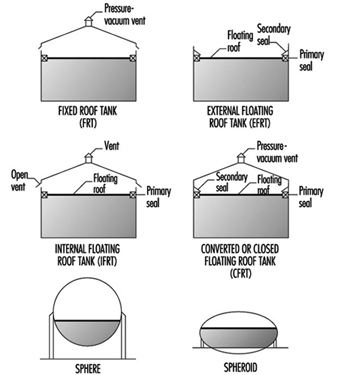
Normally, the tanks are limited to liquid storage where the liquid vapour pressure does not exceed 77 kPa. Where the pressure exceeds this value, spheroids or spheres are used since both are designed for pressure operation. Spheroids can be quite large but are not installed where the pressure may exceed certain limits defined by the mechanical design. For most higher vapour-pressure storage applications, spheres are normally the storage container and are equipped with pressure relief valves to prevent over pressuring. A safety concern that has developed with spheres is rollover, which generates excessive vapour and results in relief valve discharges or in more extreme situations such as sphere wall rupture (CCPS 1993). In general, the liquid contents stratify and if warm (less dense) material is loaded into the sphere bottom, the warm material rises to the surface with the cooler, higher density surface material rolled over to the bottom. The warm surface material vaporizes, raising the pressure, which may result in relief valve discharge or sphere overpressuring.
Tank layout
Tankage layout requires careful planning. There are recommendations for tank separation distances and other considerations (CCPS 1988; 1993). In many locations, separation distances are not specified by code, but minimum distances (OSHA 1994) can be a result of various decisions applicable to separation distances and locations. Some of these considerations are presented in table 6. In addition, tank service is a factor in tank separation for pressurized, refrigerated and atmospheric tanks (CCPS 1993).
Table 6. Tank separation and location considerations
- Separation based on shell to shell distances can be based on references and subject to calculating the thermal radiation distance in the event of fire in an adjacent tank.
- Tanks should be separated from process units.
- A tank location, preferably downwind from other areas, minimizes ignition problems in the event of a tank releasing a significant vapour quantity.
- Storage tanks should have dykes, which are also required by law in most regions.
- Tanks can be grouped for utilization of common dykes and firefighting equipment.
- Dykes should have isolation capability in an emergency.
Dykes are required and are nominally sized volumetrically to hold the contents of a tank. Where multiple tanks are within a dyke, the minimum volumetric dyke capacity is equivalent to the capacity of the largest tank (OSHA 1994). The dyke walls can be constructed of earth, steel, concrete or solid masonry. However, the earth dykes should be impenetrable and have a flat top with a minimum width of 0.61 m. In addition, the soil within the dyked area should also have an impenetrable layer to prevent any chemical or oil leakage into the soil.
Tank leakage
A problem that has been developing through the years is tank leakage as a result of corrosion in the tank bottom. Frequently, tanks have water layers in the tank bottom that can contribute to corrosion, and electrolytic corrosion may occur due to contact with the earth. As a result, regulatory requirements have been instituted in various regions to control tank bottom leakage and underground soil and water contamination from contaminants in the water. A variety of design procedures have been developed to control and monitor leakage (Hagen and Rials 1994). In addition, double bottoms have also been installed. In some installations, cathodic protection has been installed to further control metal deterioration (Barletta, Bayle and Kennelley 1995).
Water draw off
Manually discharging water periodically from the tank bottom can result in exposure. Visual observation to determine the interface through open manual draining can result in worker exposure. A closed discharge can be installed with an interface sensor and control valve minimizing potential worker exposures (Lipton and Lynch 1994). A variety of sensors are commercially available for this service.
Overfilling tanks
Frequently, tanks are overfilled, creating potential safety and worker exposure hazards. This can be prevented with redundant or dual-level instruments controlling inlet block valves or feed pumps (Bahner 1996). For many years, overflow lines were installed on chemical tanks, but they terminated a short distance above a drain opening to permit visual observation of the overflow discharge. Moreover, the drain had to be sized for greater than the maximum fill rate to ensure proper drainage. However, such a system is a potential exposure source. This can be eliminated by connecting the overflow line directly to the drain with a flow indicator in the line to show the overflow. Although this will function satisfactorily, this results in overloading the drain system with a very large contaminant volume and potential health and safety problems.
Tank inspection and cleaning
Periodically, tanks are removed from service for inspection and/ or cleaning. These procedures must be carefully controlled to prevent worker exposure and minimize potential safety hazards. Following draining, tanks are frequently flushed with water to remove process liquid traces. Historically, the tanks have then been cleaned manually or mechanically where necessary. When tanks are drained, they are filled with vapour that may be toxic and can be within a combustible range. Water flushing may not significantly affect vapour toxicity, but it may reduce potential combustion problems. With floating roofs, the material below the floating roof can be flushed and drained, but some tanks may still have material in the sump. This bottom material must be removed manually and may present potential exposure concerns. Personnel may be required to wear personal protective equipment (PPE).
Normally, enclosed tanks and any volume below the floating roofs are purged with air until a specified oxygen concentration level is achieved before entry is permitted. However, concentration measurements should be continually obtained to ensure toxic concentration levels are satisfactory and do not change.
Vapour venting and emission control
For fixed roof or converted floating roof tanks (CFRTs), venting to the atmosphere may not be acceptable in many locations. The pressure-vacuum (PV) vent (shown in figure 2 these tanks are removed and the vapours flow through a closed duct to a control device where the contaminants are destroyed or recovered. For both tanks, an inert purge (e.g., nitrogen) can be injected to eliminate the diurnal vacuum effect and maintain a positive pressure for the recovery device. In the CFRT tank, the nitrogen eliminates the diurnal effect and reduces any vapours to the atmosphere through a PV vent. However, vapour emissions are not eliminated. A large number of control devices and techniques are available including combustion, absorbers, condensers and absorption (Moretti and Mukhopadhyay 1993; Carroll and Ruddy 1993; Basta 1994; Pennington 1996; Siegall 1996). Selection of a control system is a function of final emission targets and operating and investment costs.
In floating roof tanks, both external and internal, seals and auxiliary fitting controls effectively minimize vapour losses.
Safety hazards
Flammability is a major concern in tankage and fire-fighting systems are required to aid in control and prevention of expanded fire zones. Firewater systems and installation recommendations are available (CCPS 1993; Dow Chemical Company 1994a; NFPA 1990). Water can be sprayed directly on a fire under certain conditions and is essential in cooling adjacent tankage or equipment to prevent overheating. In addition, foam is an effective fire-fighting agent and permanent foam equipment can be installed on tanks. The installation of foam equipment on mobile fire-fighting equipment should be reviewed with a manufacturer. Environmentally acceptable and low toxicity foams are now available that are effective and comparable to other foams in quickly extinguishing fires.
Processing Equipment
A wide variety of process equipment is required in chemicals processing as a result of the numerous processes, specialized process requirements and variations in products. Consequently, all of the chemical equipment in use today cannot be reviewed; this section will concentrate on the more widely applied equipment found in processing sequences.
Reactors
There are a large number of reactor types in the chemical industry. The basis for reactor selection is a function of a number of variables, beginning with classifying whether the reaction is a batch or continuous reaction. Frequently, batch reactions are converted to continuous operations as experience with the reaction increases and some modifications, such as improved catalysts, become available. Continuous reaction processing is generally more efficient and produces a more consistent product, which is desirable in meeting product quality targets. However, there are still a large number of batch operations.
Reaction
In all reactions, the classifications of a reaction as exothermic or endothermic (producing heat or requiring heat) is necessary in order to define the heating or cooling requirements necessary to control the reaction. In addition, runaway reaction criteria must be established to install instrument sensors and controls that can prevent a reaction from becoming out of control. Prior to full-scale operation of a reactor, emergency procedures must be investigated and developed to ensure the runaway reaction is safely contained. Some of the various potential solutions are emergency control equipment that is automatically activated, injection of a chemical that stops the reaction and vent facilities that can accommodate and contain the reactor contents. Safety valve and vent operation are extremely important requiring well-maintained and functioning equipment at all times. Consequently, multiple interlocked safety valves are frequently installed to ensure that maintenance on one valve will not reduce the required relief capacity.
Should a safety valve or vent discharge due to malfunction, the discharge effluent must be contained in practically all circumstances to minimize potential safety and health hazards. As a result, the method of containing the emergency discharge through piping along with final disposition of the reactor discharge should be carefully analysed. In general, liquid and vapour should be separated with the vapour sent to a flare or recovery and liquid recycled where possible. Solids removal may require some study.
Batch
In reactors involving exothermic reactions, an important consideration is fouling on the walls or internal tubing by the cooling media used to maintain the temperature. Removal of fouled material varies considerably and the method of removal is a function of the fouled material characteristics. Fouled material can be removed with a solvent, a high-pressure jet nozzle stream or, in some cases, manually. In all these procedures, safety and exposure must be carefully controlled. Movement of material in and out of the reactor must not permit the entrance of air, which may result in a flammable vapour mixture. Vacuums should be broken with an inert gas (e.g., nitrogen). Vessel entry for inspection or work can be classified as entry into a confined space and the rules for this procedure should be observed. Vapour and dermal toxicity should be understood and technicians must be knowledgeable about health hazards.
Continuous
Flow-through reactors can be filled with liquid or a vapour and liquid. Some reactions produce slurries in the reactors. Also, there are reactors that contain solid catalysts. The reaction fluid may be liquid, vapour or a combination of vapour and liquid. Solid catalysts, which promote a reaction without participating in it, are normally contained within grids and are termed fixed beds. The fixed-bed reactors may have single or multiple beds and can have exotherinic or endothermic reactions, with most reactions requiring a constant temperature (isothermal) through each bed. This frequently requires the injection of feed streams or a diluent at various locations between beds to control the temperature. With these reaction systems, temperature indication and sensor location through the beds are extremely important to prevent a reaction runaway and product yield or quality changes.
Fixed beds generally lose their activity and must be regenerated or replaced. For regeneration, deposits on the bed may be burned off, dissolved in a solvent or, in some cases, regenerated through the injection of a chemical in an inert fluid into the bed, thereby restoring catalyst activity. Depending on the catalyst, one of these techniques may be applied. Where beds are burned, the reactor is emptied and purged of all process fluids then filled with an inert gas (usually nitrogen), which is heated and recirculated, raising the bed to a specified temperature level. At this point, a very small volume of oxygen is added to the inert stream to initiate a flame front that gradually moves through the bed and controls the temperature rise. Excessive oxygen quantities have a deleterious effect on the catalyst.
Fixed-bed catalyst removal
Removal of fixed-bed catalysts must be carefully controlled. The reactors are drained of process fluid and then the remaining fluid is displaced with a flushing fluid or purged with a vapour until all of the process fluid has been removed. Final purging may require other techniques before the vessel can be purged with an inert gas or air prior to opening the vessel or discharging the catalyst from the vessel under an inert blanket. Should water be used in this process, the water is drained through closed piping to a process sewer. Some catalysts are sensitive to air or oxygen, becoming pyrophoric or toxic. These require special procedures to eliminate air during filling or emptying the vessels. Personal protection along with handling procedures must be carefully defined to minimize potential exposures and protect personnel.
Spent catalyst disposal may require further treating before it is sent to a catalyst manufacturer for recycling or into an environmentally acceptable disposal procedure.
Other catalyst systems
Gas flowing through a loose solid catalyst bed expands the bed and forms a suspension that is similar to a liquid and termed a fluid bed. This type of reaction is used in various processes. Spent catalysts are removed as a gas-solids side stream for regeneration and then returned to the process through an enclosed system. In other reactions, catalyst activity may be very high and, although catalyst is discharged in the product, the concentration is extremely low and does not pose a problem. Where a high concentration of catalyst solids in the product vapour is undesirable, solids carryover must be removed before purification. However, traces of solids will remain. These are removed for disposal in one of the by-product streams, which in turn must be clarified.
In situations where spent catalyst is regenerated through burning, extensive solids recovery facilities are required in fluid-bed systems to meet environmental restrictions. Recovery may consist of various combinations of cyclones, electric precipitators, bag filters) and/ or scrubbers. Where burning occurs in fixed beds, the basic concern is temperature control.
Since fluid-bed catalysts are frequently within the respiratory range, care must be exercised during solids handling to ensure worker protection with either fresh or recovered catalysts.
In some instances a vacuum may be used to remove various components from a fixed bed. In these situations, a steam-driven vacuum jet is frequently the vacuum producer. This produces a steam discharge that frequently contains toxic materials although in very low concentration in the jet stream. However, the discharge of a steam jet should be carefully reviewed to determine contaminant quantities, toxicity and potential dispersion if it is discharged directly to the atmosphere. Should this be unsatisfactory, the jet discharge may require condensing in a sump where all vapours are controlled and the water is sent to the closed sewer system. A rotary vacuum pump will perform in this service. The discharge from a reciprocating vacuum pump may not be permitted to discharge directly to the atmosphere, but can in some instances discharge into a flare line, incinerator or process heater.
Safety
In all reactors, pressure increases are a major concern since the vessel pressure rating must not be exceeded. These pressure increases may be a result of poor process control, malfunction or a runaway reaction. Consequently, pressure relief systems are required to maintain vessel integrity by preventing reactor overpressuring. Relief valve discharges must be carefully designed to maintain adequate relief under all conditions, including relief-valve maintenance. Multiple valves may be required. Should a relief valve be designed to discharge into the atmosphere, the discharge point should be elevated above all nearby structures and a dispersion analysis should be conducted to ensure adequate protection for workers and nearby communities.
If a rupture disk is installed with a safety valve, the discharge should also be enclosed and the final discharge location designated as described above. Since a disk rupture will not reseat, a disk without a safety valve will probably release most of the reactor contents and air may enter the reactor at the end of the release. This requires a careful analysis to ensure that a flammable situation is not created and that highly undesirable reactions do not occur. Moreover, the discharge from a disk may release liquid and the vent system must be designed to contain all liquids with vapour discharged, as described above. Atmospheric emergency releases must be approved by regulatory authorities before installation.
Mixer agitators installed in reactors are sealed. Leaks may be hazardous and if they occur the seal must be repaired which requires a reactor shutdown. The reactor contents may require special handling or precautions and an emergency shutdown procedure should include reaction termination and disposition of the reactor contents. Flammability and exposure control must be carefully reviewed for each step including final disposition of the reactor mix. Since a shutdown can be expensive and involve production loss, magnetic driven mixers and newer seal systems have been introduced to reduce maintenance and reactor shutdowns.
Entrance to all reactors requires compliance with safe confined-space entry procedures.
Fractionation or distillation towers
Distillation is a process whereby chemical substances are separated through methods which take advantage of differences in boiling points. The familiar towers in chemical plants and refineries are distillation towers.
Distillation in various forms is a processing step found in the great majority of chemical processes. Fractionation or distillation can be found in purification, separation, stripping, azeotropic and extractive process steps. These applications now include reactive distillation, where a reaction occurs in a separate section of the distillation tower.
Distillation is conducted with a series of trays in a tower, or it can be conducted in a tower filled with packing. The packings have special configurations that readily permit the passage of vapour and liquid, but provide sufficient surface area for vapour-liquid contact and efficient fractionation.
Operation
Heat is normally supplied to a tower with a reboiler, although the heat content of specific streams may be sufficient to eliminate the reboiler. With reboiler heat, multiple step vapour-liquid separation occurs on the trays and lighter materials ascend through the tower. Vapours from the top tray are fully or partially condensed in the overhead condenser. The condensed liquid is collected in the distillate recovery drum, where part of the liquid is recycled to the tower and the other portion is withdrawn and sent to a specific location. Non-condensed vapours may be recovered elsewhere or sent to a control device which can be a combustor or recovery system.
Pressure
Towers typically operate at pressures higher than atmospheric pressure. However, towers are frequently operated under vacuum to minimize liquid temperatures that may affect product quality or in situations where tower materials become a mechanical and economic concern due to the temperature level that may be difficult to achieve. Also, high temperatures may affect the fluid. In heavy petroleum fractions, very high tower bottoms temperatures frequently result in coking problems.
Vacuums are typically obtained with ejectors or vacuum pumps. In process units, vacuum loadings consist of some light vapour materials, inerts that may have been in the tower feed stream and air from leakage. Normally the vacuum system is installed after a condenser to reduce the organic loading to the vacuum system. The vacuum system is sized based upon the estimated vapour loading, with ejectors handling larger vapour loadings. In certain systems a vacuum machine may be directly connected to a condenser outlet. A typical ejector system operation is a combination of ejectors and direct barometric condensers where the ejector vapours have direct contact with the cooling water. Barometric condensers are very large consumers of water and the steam-water mixture results in high water outlet temperatures that tend to vaporize any organic compound traces in the atmospheric barometric sump, potentially increasing workplace exposures. In addition, a large effluent load is added to the waste-water system.
A large water reduction is achieved along with a substantial reduction in steam consumption in modified vacuum systems. Since the vacuum pump will not handle a large vapour load, a steam ejector is used in the first stage in combination with a surface condenser to reduce the vacuum pump load. In addition, a sump drum is installed for above-ground operation. The simpler system reduces waste-water loading and maintains a closed system that eliminates potential vapour exposures.
Safety
All towers and drums must be protected from overpressure that may result from malfunction, fire (Mowrer 1995) or utility failure. A hazard review is necessary and is required by law in some countries. A general process safety management approach that is applicable to process and plant operation improves safety, minimizes losses and protects worker health (Auger 1995; Murphy 1994; Sutton 1995). Protection is provided by pressure relief valves (PRVs) that discharge to the atmosphere or to a closed system. The PRV is generally mounted at the tower top to relieve the large vapour load, although some installations locate the PRV in other tower locations. The PRV can also be located on the distillate overhead recovery drum as long as valves are not placed between the PRV and the tower top. If block valves are installed in the process lines to the condenser then the PRV must be installed on the tower.
When distillation tower overpressure is relieved, under certain emergency scenarios, the PRV discharge may be exceedingly large. Very high loading in a closed system discharge vent line may be the largest load in the system. Since a PRV discharge can be sudden and the overall relieving time may be quite short (less than 15 minutes), this extremely large vapour load must be carefully analysed (Bewanger and Krecter 1995; Boicourt 1995). Since this short, large peak load is difficult to process in control devices such as absorbers, adsorbers, furnaces and so on, the preferable control device in most situations is a flare for vapour destruction. Normally, a number of PRVs are connected to a flare line header that in turn is connected to a single flare. However, the flare and overall system must be carefully designed to cover a large group of potential contingencies (Boicourt 1995).
Health hazards
For direct relief to the atmosphere, a detailed dispersion analysis of the relief valve discharge vapours should be conducted to ensure that workers are not exposed and that community concentrations are well within allowable concentration guidelines. In controlling dispersion, atmospheric relief valve discharge lines may have to be raised to prevent excessive concentrations on nearby structures. A very tall flare-like stack may be necessary to control dispersion.
Another area of concern is entering a tower for maintenance or mechanical changes during a shutdown. This entails entering a confined space and exposes workers to the associated hazards. The flushing and purging method prior to opening must be carefully conducted to ensure minimal exposures by reducing any toxic concentrations below recommended levels. Before commencing with flushing and purging operations, the tower pressure must be reduced and all piping connections to the tower must be blinded (i.e., flat metal disks must be placed between the tower flanges and the connecting pipe flanges). This step should be carefully managed to ensure minimum exposures. In different processes, the methods of clearing the tower of toxic fluids vary. Frequently, the tower fluid is displaced with a fluid that has very low toxicity characteristics. This displacement fluid is then drained and pumped to a selected location. The remaining liquid film and droplets can be steamed to the atmosphere through a top flange that has a special stand-off blind with an opening between the blind and tower flange. Following steaming, air enters the tower through the special blind opening as the tower cools. A manhole at the tower bottom and one at the tower top are opened permitting the blowing of air through the tower. When the internal tower concentration reaches a predetermined level, the tower can be entered.
Heat exchangers
There are a wide variety of heat exchangers in the chemical process industry. Heat exchangers are mechanical devices for the transfer of heat to or from a process stream. They are selected in accordance with process conditions and exchanger designs. A few of the common exchanger types are shown in figure 2. Selection of the optimum exchanger for a process service is somewhat complicated and requires a detailed investigation (Woods 1995). In many situations, certain types are not suitable because of pressure, temperature, solids concentration, viscosity, flow quantity and other factors. Moreover, an individual heat exchanger design can vary considerably; several types of floating head tube and sheet exchangers are available (Green, Maloney and Perry 1984). The floating head is normally selected where the temperatures may cause excessive tube expansion that otherwise could not maintain integrity in a fixed tube sheet exchanger. In the simplified floating head exchanger in figure 2, the floating head is contained completely within the exchanger and does not have any connection with the shell cover. In other floating head designs, there may be packing around the floating tubesheet (Green, Maloney and Perry 1984).
Figure 2. Typical heat exchangers
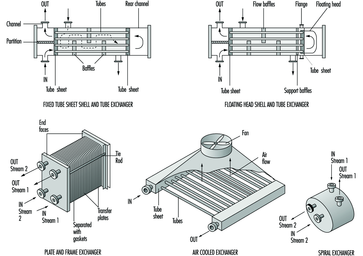
Leakage
The packing on floating tubesheets is in contact with the atmosphere and may be a source of leakage and potential exposure. Other exchangers may also have potential leakage sources and should be examined carefully. As a result of their heat transfer characteristics, plate and frame exchangers are often installed in the chemical industry. The plates have various corrugations and configurations. Plates are separated by gaskets that prevent mixing of the streams and provide an external seal. However, the seals limit temperature applications to about 180 ºC, although seal improvements may overcome this limitation. Since there are a number of plates, the plates must be compressed properly to ensure proper sealing between them. Consequently, careful mechanical installation is necessary to prevent leakage and potential hazards. Since there are a large number of seals, careful seal monitoring is important to minimize potential exposures.
Air cooled exchangers are attractive economically and have been installed in a wide number of process applications and in various locations within process units. To save space, these exchangers are often installed over pipe runs and are frequently stacked. Since tube material selection is important, a variety of materials is used in the chemical industry. These tubes are connected to the tube sheet. This requires use of compatible materials. Leakage through a tube crack or at the tube sheet is a concern since the fan will circulate vapours from the leak and dispersion may result in potential exposures. Air dilution may significantly reduce the potential exposure hazard. However, fans are frequently shut down under some weather conditions and in these circumstances leak concentrations can increase thereby increasing potential exposures. Moreover, if leaking tubes are not repaired, the crack may worsen. With toxic liquids that do not readily vaporize, dripping can occur and result in potential dermal exposure.
Shell and tube heat exchangers may develop leaks through any of the various flanges (Green, Maloney and Perry 1984). Since shell and tube heat exchangers vary in size from small to very large surface areas, the diameter of outer flanges is generally much larger than typical pipe flanges. With these large flanges, the gaskets must not only withstand process conditions, but provide a seal under bolt load variations. Various gasket designs are used. Maintaining constant bolt load stresses on all of the flange bolts is difficult, resulting in leakage in many exchangers. The flange leakage can be controlled with flange sealing rings (Lipton and Lynch 1994).
Tube leakage may occur in any of the available exchanger types, with the exception of plate exchangers and a few other specialty exchangers. However, these latter exchangers have other potential problems. Where tubes leak into a cooling water system, the cooling water discharges the contaminant into a cooling tower which can be an exposure source to both workers and a nearby community. Consequently, the cooling water should be monitored.
The dispersion of cooling tower vapours can be widespread as a result of the fans in forced and induced draft cooling towers. In addition, natural convection towers discharge vapours to the atmosphere which then disperse. However, dispersion varies considerably based upon both weather conditions and the discharge elevation. Less volatile toxic materials remain in the cooling water and the cooling tower blowdown stream, which should have sufficient treatment capability to destroy contaminants. The cooling tower and tower basin must be cleaned periodically and contaminants add to the potential hazards in the basin and in the tower fill. Personal protection is necessary for much of this work.
Exchanger cleaning
A problem with tubes in cooling water service is the build-up of material in the tubes resulting from corrosion, biological organisms and solids deposition. As described above, tubes may also leak through cracks, or leakage may occur where tubes are rolled into striations in the tube sheet. When any of these conditions occur, exchanger repair is required and the process fluids must be removed from the exchanger. This requires a completely contained operation, which is necessary to meet environmental, safety and health exposure objectives.
Generally, the process fluid is drained to a receiver and the remaining material is flushed out of the exchanger with a solvent or inert material. The latter material is also sent to a receiver for the contaminated material by draining or pressuring with nitrogen. Where toxic material was in the exchanger, the exchanger should be monitored for any traces of toxic material. If testing results are unsatisfactory, the exchanger can be steamed to vaporize and remove all traces of material. However, the steam vent should be connected to a closed system to prevent vapour escape into the atmosphere. While the closed vent may not be absolutely necessary, at times there may be more contaminant material in the exchanger, requiring closed steam venting at all times to control potential hazards. Following steaming, a vent to the atmosphere admits air. This general procedure is applicable to the exchanger side or sides containing toxic material.
Chemicals then used for cleaning the tubes or the shell side should be circulated in a closed system. Normally, the cleaning solution is recirculated from a tank truck system and the contaminated solution in the system is drained to a truck for disposition.
Pumps
One of the most important process functions is the movement of liquids and in the chemical industry all types of liquid materials are moved with a wide variety of pumps. Canned and magnetic pumps are sealless centrifugal pumps. Magnetic pump drivers are available for installation on other pump types to prevent leakage. Types of pumps used in the chemical process industry are listed in table 7.
Table 7. Pumps in the chemicals process industry
- Centrifugal
- Reciprocating (plunger)
- Canned
- Magnetic
- Turbine
- Gear
- Diaphragm
- Axial flow
- Screw
- Moving cavity
- Lobe
- Vane
Sealing
From a health and safety standpoint, sealing and repairing centrifugal pumps are major concerns. Mechanical seals, which constitute the prevalent shaft sealing system, can leak and at times have blown out. However, there have been major advances in seal technology since the 1970s that have resulted in significant leakage reductions and extended pump service life. Some of these improvements are bellows seals, cartridge seals, improved face designs, better face materials and improvements in pump variable monitoring. Moreover, continuing research in seal technology should result in further technology improvements.
Where process fluids are highly toxic, leakless or sealless canned or magnetic pumps are frequently installed. Operating service periods or the mean time between maintenance (MTBM) has improved markedly and generally varies between three and five years. In these pumps, the process fluid is the lubricating fluid for the rotor bearings. Vaporization of the internal fluid adversely affects the bearings and often makes bearing replacement necessary. Liquid conditions in the pumps can be maintained by ensuring the internal pressure in the bearing system is always greater than the liquid vapour pressure at the operating temperature. When repairing a sealless pump, completely draining a relatively low volatility material is important and should be carefully reviewed with the supplier.
In typical centrifugal process pumps, packing has essentially been replaced with mechanical seals. These seals are generally classified as single or dual mechanical seals, with the latter term covering tandem or double mechanical seals. There are other dual seal combinations, but they are not as widely used. In general, tandem or double mechanical seals with liquid buffer fluids between the seals are installed to reduce seal leakage. Pump mechanical seal standards for both centrifugal and rotary pumps covering single and dual mechanical seal specification and installation were issued by the American Petroleum Institute (API 1994). A mechanical seal application guide is now available to aid in the evaluation of seal types (STLE 1994).
To prevent excessive leakage or blow-out from a failed seal, a gland plate is installed following the seal. It may have a gland flush fluid to move the leakage into a closed drain system (API 1994). Since the gland system is not a complete seal, auxiliary seal systems, such as throttle bushings are available.They are installed in the gland that controls excessive leakage to the atmosphere or seal blow-out (Lipton and Lynch 1994). These seals are not designed for continuous operation; after activation they will operate for up to two weeks before failure, thereby providing time for operations to switch pumps or make process adjustments.
A newer mechanical seal system is available that essentially reduces emissions to the nil level. This is a double mechanical seal system with a gas buffer system that replaces the liquid buffer in the standard dual mechanical seal system (Fone 1995; Netzel 1996; Adams, Dingman and Parker 1995). In the liquid buffer systems, the seal faces are separated by an extremely thin lubricating film of buffer fluid that also cools the seal faces. Although separated slightly, a certain amount of face contact exists which results in seal wear and seal face heating. The gas seals are called non-contact seals since one seal face with curved indentations pumps gas through the seal faces and builds a gas layer or dam that completely separates the seal faces. This lack of contact results in a very long seal life and also reduces the seal friction loss, thereby noticeably decreasing power consumption. Since the seal pumps gas there is a very small flow into the process and to the atmosphere.
Health hazards
A major concern with pumps is draining and flushing to prepare the pump for maintenance or repair. Draining and removal covers both process fluid and buffer fluids. Procedures should require discharge of all fluids into a closed connection drain system. In the pump stuffing box where a throat bushing separates the impeller from the stuffing box, the bushing acts as a weir in holding some liquid in the stuffing box. Weep holes in the bushing or a drain in the stuffing box will permit complete process liquid removal through draining and flushing. For buffer fluids, there should be a method of draining all fluid from the dual seal area. Maintenance requires seal removal and if the seal volume is not completely drained and flushed, the seals are a potential source of exposure during repair.
Dust and powders
Handling of dusts and powders in solids processing equipment is a concern due to the potential for fire or explosion. An explosion within equipment may burst through a wall or enclosure as a result of explosion-generated pressure sending a combined pressure and fire wave into the workplace area. Workers can be at risk, and adjacent equipment can be severely impacted with drastic effects. Dusts or powders suspended in air or in a gas with oxygen present and in a confined space are susceptible to explosion when a source of ignition with sufficient energy is present. Some typical explosive equipment environments are shown in table 8.
Table 8. Potential explosion sources in equipment
|
Conveying equipment |
Storage |
|
Pneumatic ducts |
Bins |
|
Mechanical conveyors |
Hoppers |
|
Rotary valves |
|
|
Processing equipment |
|
|
Filter dust collectors |
Grinders |
|
Fluid bed dryers |
Ball mills |
|
Transfer line dryers |
Powder mixing |
|
Screening |
Cyclones |
An explosion produces heat and rapid gas expansion (pressure increase) and generally results in deflagration, which is a flame front that moves rapidly but at less than the sound velocity for these conditions. When the flame front velocity is greater than the sound velocity or is at supersonic velocity the condition is termed detonation, which is more destructive than deflagration. Explosion and flame front expansion occur in milliseconds and do not provide sufficient time for standard process responses. Consequently, the potential fire and explosion characteristics of the powder must be defined to determine the potential hazards that may exist in the various processing steps (CCPS 1993; Ebadat 1994; Bartknecht 1989; Cesana and Siwek 1995). This information can then provide a basis for the installation of controls and the prevention of explosions.
Explosion hazard quantification
Since the explosions generally occur in enclosed equipment, various tests are conducted in specially-designed laboratory equipment. While powders may appear similar, published results should not be used since small differences in the powders can have very different explosion characteristics.
A variety of tests conducted on powder can define the explosion hazard and the test series should encompass the following.
The classification test determines whether a powder dust cloud can initiate and propagate flames (Ebadat 1994). Powders that have these characteristics are considered Class A powders. Those powders that do not ignite are termed Class B. The Class A powders then require a further series of tests to evaluate their explosion and hazard potential.
The minimum ignition energy test defines the minimum spark energy necessary for ignition of a powder cloud (Bartknecht 1989).
In explosion severity and analysis Group A powders are then tested as a dust cloud in a sphere where the pressure is measured during a test explosion based on minimum ignition energy. The maximum explosion pressure is defined along with the rate of change in pressure per unit time. From this information, the explosion specific characteristic value (Kst) in bar metres per second is determined and the explosion class is defined (Bartknecht 1989; Garzia and Senecal 1996):
Kst(bar·m/s) Dust explosion class Relative strength
1-200 St 1 Somewhat weaker
201-300 St 2 Strong
300+ St 3 Very strong
A large number of powders have been tested and the majority were in the St 1 class (Bartknecht 1989; Garzia and Senecal 1996).
In assessment of non-cloud powders, powders are tested to determine safe operating procedures and conditions.
Explosion prevention tests
Explosion prevention tests can be helpful where explosion suppression systems cannot be installed. They provide some information on desirable operating conditions (Ebadat 1994).
The minimum oxygen test defines the oxygen level below which the dust will not ignite (Fone 1995). Inert gas in the process will prevent ignition if the gas is acceptable.
The minimum dust concentration is determined in order to establish the operating level below which ignition will not occur.
Electrostatic hazard tests
Many explosions are a result of electrostatic ignitions and various tests indicate the potential hazards. Some of the tests cover the minimum ignition energy, powder electric charge characteristics and volume resistivity. From the test results, certain steps can be taken to prevent explosions. Steps include increasing humidity, modifying construction materials, proper grounding, controlling certain aspects of equipment design and preventing sparks (Bartknecht 1989; Cesana and Siwek 1995).
Explosion control
There are basically two methods of controlling explosions or fronts from propagating from one location and another or containing an explosion within a piece of equipment. These two methods are chemical suppressants and isolation valves (Bartknecht 1989; Cesana and Siwek 1995; Garzia and Senecal 1996). Based upon the explosion pressure data from the explosion severity tests, rapid response sensors are available that will trigger a chemical suppressant and/ or rapidly close isolation barrier valves. Suppressants are commercially available, but suppressant injector design is very important.
Explosion vents
In equipment where a potential explosion may occur, explosion vents that rupture at specific pressures are frequently installed. These must be carefully designed and the exhaust path from the equipment must be defined to prevent a worker presence in this path area. Moreover, impingement on equipment in the explosion path should be analysed to ensure equipment safety. A barrier may be required.
Loading and Unloading
Products, intermediates and by-products are loaded into tank trucks and railcars. (In some cases, depending on location of facilities and dockage requirements, tankers and barges are used.) Location of the loading and unloading facilities are important. While the materials loaded and unloaded usually are liquids and gases, solids are also loaded and unloaded at preferred locations based upon the type of solids moved, potential explosion hazard and the degree of transfer difficulty.
Open hatches
In loading tank trucks or railcars through top opening hatches, a very important consideration is minimizing splashing as the container is filled. If the fill pipe is located well above the bottom of the container, filling results in splashing and generation of vapour or mixed liquid-vapour evolvement. Splashing and vapour generation can be minimized by locating the fill pipe outlet well below the liquid level. The fill pipe is normally extended through the container a minimum distance above the container bottom. Since liquid filling also displaces vapour, toxic vapours can be a potential health hazard and also present safety concerns. Consequently, the vapours should be collected. Fill arms are commercially available that have deep fill pipes and extend through a special cover that closes the hatch opening (Lipton and Lynch 1994). In addition, a vapour collection pipe extends a short distance below the special hatch cover. At the upstream end of the arm, the vapour outlet is connected to a recovery device (e.g., an absorber or condenser), or the vapour can be returned to the storage tank as a vapour balance transfer (Lipton and Lynch 1994).
In the tank truck open hatch system, the arm is raised to permit draining into the tank truck and some of the liquid in the arm can be pressured with nitrogen as the arm is withdrawn, but the fill pipes during this operation should remain within the hatch opening. As the fill arm clears the hatch, a bucket should be placed over the outlet to catch arm drippings.
Railcars
Many railcars have closed hatches with deep fill legs very close to the bottom of the container and a separate vapour collection outlet. Through an arm that extends to the closed hatch, liquid is loaded and vapour collected in a fashion similar to the open hatch arm method. In railcar loading systems, following valve shut off at the arm inlet, nitrogen is injected into the container side of the arms to blow the liquid remaining in the arm into the railcar before the fill valve on the railcar is closed (Lipton and Lynch 1994).
Tank trucks
Many tank trucks are filled through the bottom to minimize vapour generation (Lipton and Lynch 1994). The fill lines can be special hoses or manoeuvrable arms. Dry break couplers are placed on the hose or arm ends and on the tank truck bottom connections. When the tank truck is filled and the line is automatically blocked, the arm or hose is disconnected at the drybreak coupling, which automatically closes as the couplings are separated. Newer couplings have been designed to disconnect with almost zero leakage.
In bottom loading, vapour is collected through a top vapour vent and the vapour is conducted through an external line that terminates near the bottom of the container (Lipton and Lynch 1994). This permits worker access to the vapour coupling connections. The collected vapour, which is at a pressure slightly above atmospheric, must be collected and sent to a recovery device (Lipton and Lynch 1994). These devices are selected based upon initial cost, effectiveness, maintenance and operability. Generally, the recovery system is preferable to a flare, which destroys the recovered vapours.
Loading control
In tank trucks, level sensors are permanently installed within the truck body to indicate when the fill level has been reached and signal a remote control block valve that stops flow to the truck. (Lipton and Lynch 1994). There may be more than one sensor in the tank truck as backup to ensure that the truck is not overfilled. Overfilling can result in serious safety and health exposure problems.
Railcars in dedicated chemical service may have level sensors mounted internally in the car. For non-dedicated cars, a flow totalizer controls the amount of liquid sent to the railcar and automatically shuts the remote control block valve at a predetermined setting (Lipton and Lynch 1994). Both container types should be investigated to determine whether liquid remains in the container prior to filling. Many railcars have manual level indicators that can be used for this service. However, where level is shown by opening a small level stick vent to the atmosphere, this procedure should only be performed under properly controlled and approved conditions due to the toxicity of some of the loaded chemicals.
Unloading
Where chemicals have a very high vapour pressure and the railcar or tank truck has a relatively high pressure, the chemical is unloaded under its own vapour pressure. Should the vapour pressure fall to a level that will interfere with the unloading procedure, nitrogen gas can be injected to maintain a satisfactory pressure. Vapour from a tank of the same chemical can also be compressed and injected to raise the pressure.
For toxic chemicals that have a relatively low vapour pressure, such as benzene, the liquid is unloaded under nitrogen pressure, which eliminates pumping and simplifies the system (Lipton and Lynch 1994). Tank trucks and railcars for this service have design pressures capable of handling the pressures and variations encountered. However, lower pressures after unloading a container are maintained until the tank truck or railcar is refilled; the pressure rebuilds during loading. Nitrogen can be added if sufficient pressure has not been attained during loading.
One of the problems in loading and unloading operations is draining and purging lines and equipment in the loading/unloading facilities. Closed drains and particularly low point drains are necessary with nitrogen purges to remove all traces of the toxic chemicals. These materials can be collected in a drum and returned to a receiving or recovery facility (Lipton and Lynch 1994).
Plastics Industry
Adapted from 3rd edition, Encyclopaedia of Occupational Health and Safety
The plastics industry is divided into two major sectors, the inter-relationship of which can be seen in figure 1. The first sector comprises the raw material suppliers who manufacture polymers and moulding compounds from intermediates which they may also have produced themselves. In terms of invested capital this is usually the largest of the two sectors. The second sector is made up of processors who convert the raw materials into saleable items using various processes such as extrusion and injection moulding. Other sectors include machinery manufacturers who supply equipment to the processors and suppliers of special additives for use within the industry.
Figure 1. Production sequence in the processing of plastics
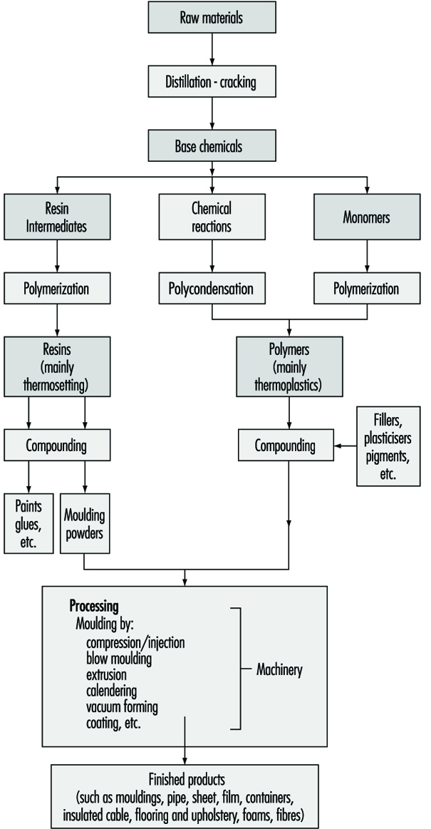
Polymer Manufacturing
Plastics materials fall broadly into two distinct categories: thermoplastics materials, which can be softened repeatedly by the application of heat and thermosetting materials, which undergo a chemical change when heated and shaped and cannot thereafter be reshaped by the application of heat. Several hundred individual polymers can be made with widely differing properties but as few as 20 types constitute about 90% of total world output. Thermoplastics are the largest group and their production is increasing at a higher rate than the thermosetting. In terms of production quantity the most important thermoplastics are high and low density polyethylene and polypropylene (the polyolefins), polyvinyl chloride (PVC) and polystyrene.
Important thermosetting resins are phenol-formaldehyde and urea-formaldehyde, both in the form of resins and moulding powders. Epoxy resins, unsaturated polyesters and polyurethanes are also significant. A smaller volume of “engineering plastics”, for example, polyacetals, polyamides and polycarbonates, have a high value in use in critical applications.
The considerable expansion of the plastics industry in the post Second World War world was greatly facilitated by the broadening of the range of the basic raw materials feeding it; availability and price of raw materials are crucial to any rapidly developing industry. Traditional raw materials could not have provided chemical intermediates in sufficient quantities at an acceptable cost to facilitate the economic commercial production of large-tonnage plastics materials and it was the development of the petrochemicals industry which made growth possible. Petroleum as a raw material is abundantly available, easily transported and handled and was, until the oil crisis of the 1970s, relatively cheap. Therefore, throughout the world, the plastics industry is primarily tied to the use of intermediates obtained from oil cracking and from natural gas. Unconventional feedstocks like biomass and coal have not yet had a major impact on supply to the plastics industry.
The flow chart in figure 2 illustrates the versatility of crude petroleum and natural gas feedstocks as starting points for the important thermosetting and thermoplastics materials. Following the first processes of crude oil distillation, naphtha feedstock is either cracked or reformed to provide useful intermediates. Thus the ethylene produced by the cracking process is of immediate use for the manufacture of polyethylene or for utilization in another process which provides a monomer, vinyl chloride—the basis of PVC. Propylene, which also arises during the cracking process, is used via either the cumene route or the isopropyl alcohol route for the manufacture of acetone needed for polymethylmethacrylate; it is also used in the manufacture of propylene oxide for polyester and polyether resins and again may be polymerized directly to polypropylene. Butenes find use in the manufacture of plasticisers and 1,3-butadiene is utilized directly for synthetic rubber manufacture. Aromatic hydrocarbons such as benzene, toluene and xylene are now widely produced from the derivatives of oil distillation operations, instead of being obtained from coal-coking processes; as the flow chart shows, these are intermediates in the manufacture of important plastics materials and auxiliary products such as plasticizers. The aromatic hydrocarbons are also a starting point for many polymers required in the synthetic fibres industry, some of which are discussed elsewhere in this Encyclopaedia.
Figure 2. Production of raw materials into plastics
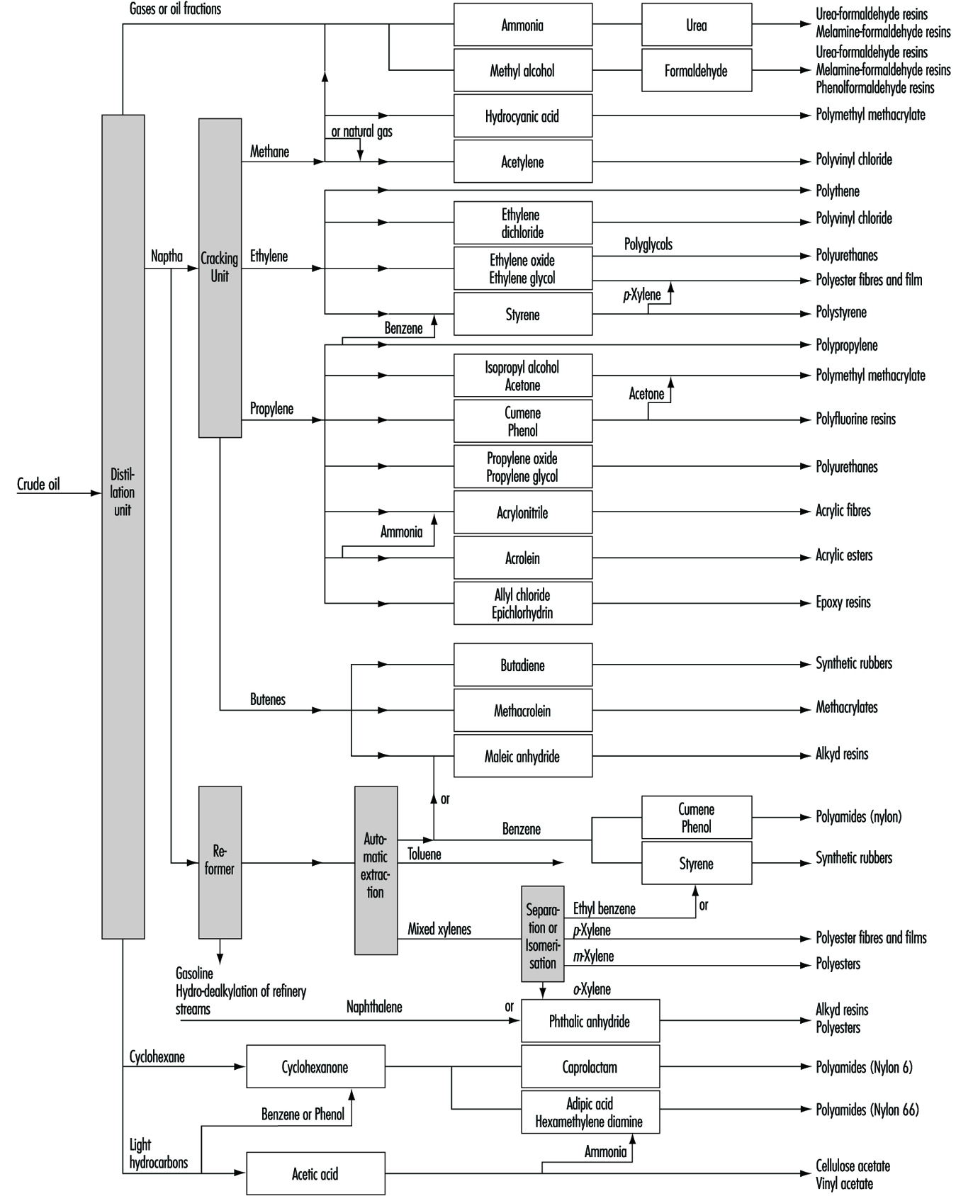
Many widely differing processes contribute to the final production of a finished article made wholly or partly of plastics. Some processes are purely chemical, some involve purely mechanical mixing procedures while others-particularly those towards the lower end of the diagram-involve extensive use of specialized machinery. Some of this machinery resembles that used in rubber, glass, paper and textile industries; the remainder is specific to the plastics industry.
Plastics processing
The plastics processing industry converts bulk polymeric material into finished articles.
Raw materials
The processing section of the plastics industry receives its raw materials for production in the following forms:
- fully compounded polymeric material, in the form of pellets, granules or powder, which is fed directly into the machinery for processing
- uncompounded polymer, in the form of granules or powder, which must be compounded with additives before it is suitable for feeding into to machinery
- polymeric sheet, rod, tube and foil materials which are processed further by the industry
- miscellaneous materials which can be fully polymerized matter in the form of suspensions or emulsions (generally known as latices) or liquids or solids which can polymerise, or substances in an intermediate state between the reactive raw materials and the final polymer. Some of these are liquids and some true solutions of partially polymerised matter in water of controlled acidity (pH) or in organic solvents.
Compounding
The manufacture of compound from polymer entails the mixing of the polymer with additives. Though a great variety of machinery is employed for this purpose, where powders are dealt with, ball mills or high-speed propeller mixers are most common, and where plastic masses are being mixed, kneading machines such as the open rolls or Banbury-type mixers, or extruders themselves are normally employed.
The additives required by the industry are many in number, and range widely in chemical type. Of some 20 classes, the most important are:
- plasticisers—generally esters of low volatility
- antioxidants—organic chemicals to protect against thermal decomposition during processing
- stabilisers—inorganic and organic chemicals to protect against thermal decomposition and against degradation from radiant energy
- lubricants
- fillers—inexpensive matter to confer special properties or to cheapen compositions
- colourants—inorganic or organic matter to colour compounds
- blowing agents—gases or chemicals that emit gases to produce plastic foams.
Conversion processes
All the conversion processes call on the “plastic” phenomenon of polymeric materials and fall into two types. Firstly, those where the polymer is brought by heat to a plastic state in which it is given a mechanical constriction leading to a form which it retains on consolidation and cooling. Secondly, those in which a polymerisable material-which may be partially polymerised-is fully polymerised by the action of heat, or of a catalyst or by both acting together whilst under a mechanical constraint leading to a form which it retains when fully polymerised and cold. Plastics technology has developed to exploit these properties to produce goods with the minimum of human effort and the greatest consistency in physical properties. The following processes are commonly used.
Compression moulding
This consists of heating a plastic material, which can be in the form of granules or powder, in a mould which is held in a press. When the material becomes “plastic” the pressure forces it to conform to the shape of the mould. If the plastic is of the type that hardens on heating, the formed article is removed after a short heating period by opening the press. If the plastic does not harden on heating, cooling must be effected before the press can be opened. Articles made by compression moulding include bottle caps, jar closures, electric plugs and sockets, toilet seats, trays and fancy goods. Compression moulding is also employed to make sheet for subsequent forming in the vacuum forming process or for building into tanks and large containers by welding or by lining existing metal tanks.
Transfer moulding
This is a modification of compression moulding. The thermosetting material is heated in a cavity and then forced by a plunger into the mould, which is physically separate and independently heated from the heating cavity. It is preferred to normal compression moulding when the final article has to carry delicate metallic inserts such as in small electrical switchgear, or when, as in very thick objects, completion of the chemical reaction could not be obtained by normal compression moulding.
Injection moulding
In this process, plastics granules or powders are heated in a cylinder (known as the barrel), which is separate from the mould. The material is heated until it becomes fluid, while it is conveyed through the barrel by a helical screw and then forced into the mould where it cools and hardens. The mould is then opened mechanically and the formed articles are removed (see figure 3). This process is one of the most important in the plastics industry. It has been extensively developed and has become capable of making articles of considerable complexity at very low cost.
Figure 3. An operator removing a polypropylene bowl from an injection-moulding machine.
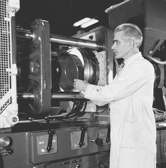
Though transfer and injection moulding are identical in principle, the machinery employed is very different. Transfer moulding is normally restricted to thermosetting materials and injection moulding to thermoplastics.
Extrusion
This is the process in which a machine softens a plastic and forces it through a die which gives it the shape that it retains on cooling. The products of extrusion are tubes or rods which may have cross sections of almost any configuration (see figure 4). Tubes for industrial or domestic purposes are produced in this way, but other articles can be made by subsidiary processes. For example, sachets can be made by cutting tubes and sealing both ends, and bags from thin-walled flexible tubes by cutting and sealing one end.
The process of extrusion has two major types. In one, a flat sheet is produced. This sheet can be converted into useful goods by other processes, such as vacuum forming.
Figure 4. Plastic extrusion: The ribbon is chopped to make pellets for injection moulding machines.
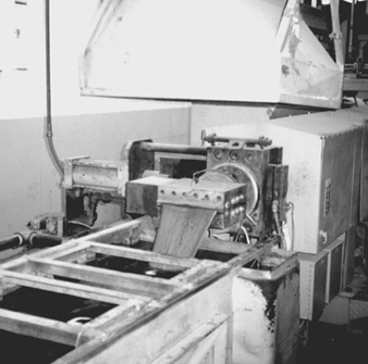
Ray Woodcock
The second is a process in which the extruded tube is formed and when still hot is greatly expanded by a pressure of air maintained inside the tube. This results in a tube which can be several feet in diameter with a very thin wall. On slitting, this tube gives film which is extensively used in the packaging industry for wrapping. Alternatively the tube can be folded flat to give a two-layer sheet which can be used to make simple bags by cutting and sealing. Figure 5 provides an example of appropriate local ventilation on an extrusion process.
Figure 5. Plastic extrusion with local exhaust hood and water bath at extruder head
Ray Woodcock
Calendering
In this process, a plastic is fed to two or more heated rollers and forced into a sheet by passing through a nip between two such rollers and cooling thereafter. Sheet thicker than film is made in this way. Sheet so made is employed in industrial and domestic applications and as the raw material in the manufacture of clothing and inflated goods such as toys (see figure 6).
Figure 6. Canopy hoods to capture hot emissions from warm-up mills on a calender process

Ray Woodcock
Blow moulding
This process can be regarded as a combination of the process of extrusion and thermo-forming. A tube is extruded downwards into an opened mould; as it reaches the bottom the mould is closed round it and the tube expanded by air pressure. Thus the plastic is forced to the sides of the mould and the top and bottom sealed. On cooling, the article is taken from the mould. This process makes hollow articles of which bottles are the most important.
The compression and impact strength of certain plastic products made by blow moulding can be considerably improved by using stretch-blow moulding techniques. This is achieved by producing a pre-form which is subsequently expanded by air pressure and stretched biaxially. This has led to such an improvement in the burst pressure strength of PVC bottles that they are used for carbonated drinks.
Rotational moulding
This process is used for the production of moulded articles by heating and cooling a hollow form which is rotated to enable gravity to distribute finely divided powder or liquid over the inner surface of that form. Articles produced by this method include footballs, dolls and other similar articles.
Film casting
Apart from the extrusion process, films can be formed by extruding a hot polymer on to a highly polished metal drum, or a solution of polymer can be sprayed on to a moving belt.
An important application of certain plastics is the coating of paper. In this, a film of molten plastic is extruded on to paper under conditions in which the plastic adheres to the paper. Board can be coated in the same way. Paper and board so coated are widely used in packaging, and board of this type is used in box making.
Thermo-forming
Under this heading are grouped a number of processes in which a sheet of a plastic material, more often than not thermoplastic, is heated, generally in an oven, and after clamping at the perimeter is forced to a predesigned shape by pressure which may be from mechanically operated rams or by compressed air or steam. For very large articles the “rubbery” hot sheet is manhandled with tongs over formers. Products so made include external light fittings, advertising and directional road signs, baths and other toilet goods and contact lenses.
Vacuum-forming
There are many processes which come under this general heading, all of which are aspects of thermal forming, but they all have in common that a sheet of plastic is heated in a machine above a cavity, around the edge of which it is clamped, and when pliable it is forced by suction into the cavity, where it takes some specific form and cools. In a subsequent operation, the article is trimmed free from the sheet. These processes produce very cheaply thin-walled containers of all types, as well as display and advertising goods, trays and similar articles, and shock-absorbing materials for packing goods such as fancy cakes, soft fruit and cut meat.
Laminating
In all of the various laminating processes, two or more materials in the form of sheets are compressed to give a consolidated sheet or panel of special properties. At one extreme are found decorative laminates made from phenolic and amino resins, at the other complex films used in packaging having, for example, cellulose, polyethylene and metal foil in their constitution.
Resin technology processes
These include plywood manufacture, furniture manufacture and the construction of large and elaborate articles such as car bodies and boat hulls from glass fibre impregnated with polyester or epoxy resins. In all these processes, a liquid resin is caused to consolidate under the action of heat or of a catalyst and so bind together discrete particles or fibres or mechanically weak films or sheets, resulting in a robust panel of rigid construction. These resins can be applied by hand layup techniques such as brushing and dipping or by spraying.
Small objects such as souvenirs and plastic jewellery can also be made by casting, where the liquid resin and catalyst are mixed together and poured into a mould.
Finishing processes
Included under this heading are a number of processes common to many industries, for example the use of paints and adhesives. There are, however, a number of specific techniques used for the welding of plastics. These include the use of solvents such as chlorinated hydrocarbons, methyl ethyl ketone (MEK) and toluene, which are used for bonding together rigid plastic sheets for general fabrication, advertising display stands and similar work. Radiofrequency (RF) radiation utilizes a combination of mechanical pressure and electromagnetic radiation with frequencies generally in the range of 10 to 100 mHz. This method is commonly used for welding together flexible plastic material in the manufacture of wallets, briefcases and children’s push chairs (see the accompanying box). Ultrasonic energies are also used in combination with mechanical pressure for a similar range of work.
RF dielectric heaters and sealers
Radiofrequency (RF) heaters and sealers are used in many industries to heat, melt or cure dielectric materials, such as plastics, rubber and glue which are electrical and thermal insulators and hard to heat using normal methods. RF heaters are commonly used for sealing polyvinyl chloride (e.g., manufacture of plastic products such as raincoats, seat covers and packaging materials); curing of glues used in woodworking; embossing and drying of textiles, paper, leather and plastics; and curing of many materials containing plastic resins.
RF heaters use RF radiation in the frequency range 10 to 100MHz with output power from under 1kW to about 100kW to produce heat. The material to be heated is placed between two electrodes under pressure, and the RF power is applied for periods ranging from a few seconds to about a minute, depending on the use. RF heaters can produce high stray RF electric and magnetic fields in the surrounding environment, especially if the electrodes are unshielded.
Absorption of RF energy by the human body can cause localized and whole body heating, which can have adverse health effects. The body temperature can rise 1 °C or more, which can cause cardiovascular effects such as increased heart rate and cardiac output. Localized effects include eye cataracts, lowered sperm counts in the male reproductive system and teratogenic effects in the developing foetus.
Indirect hazards include RF burns from direct contact with metal parts of the heater which are painful, deep seated and slow to heal; hand numbness; and neurological effects, including carpal tunnel syndrome and peripheral nervous system effects.
Controls
The two basic types of controls that can be used to reduce hazards from RF heaters are work practices and shielding. Shielding, of course, is preferred, but proper maintenance procedures and other work practices can also reduce exposure. Limiting the amount of time the operator is exposed, an administrative control, has also been used.
Proper maintenance or repair procedures are important because failure to properly reinstall shielding, interlocks, cabinet panels and fasteners can result in excessive RF leakage. In addition, electric power to the heater should be disconnected and locked out or tagged out to protect maintenance personnel.
Operator exposure levels can be reduced by keeping the operator’s hands and upper body as far as possible from the RF heater. The operator’s control panels for some automated heaters are positioned at a distance from the heater electrodes by using shuttle trays, turning tables or conveyor belts to feed the heater.
The exposure of both operating and non-operating personnel can be reduced by measuring RF levels. Since RF levels decrease with increasing distance from the heater, an “RF hazard area” can be identified around each heater. Workers can be alerted to not occupy these hazard areas when the RF heater is being operated. Where possible, nonconductive physical barriers should be used to keep people at a safe distance.
Ideally, RF heaters should have a box shield around the RF applicator to contain the RF radiation. The shield and all joints should have high conductivity for the interior electrical currents that will flow in the walls. There should be as few openings in the shield as possible, and they should be as small as is practical for operation. The openings should be directed away from the operator. Currents in the shield can be minimized by having separate conductors inside the cabinet to conduct high currents. The heater should be properly grounded, with the ground wire in the same pipe as the power line. The heater should have proper interlocks to prevent exposure to high voltages and high RF emissions.
It is much easier to incorporate this shielding into new designs of RF heaters by the manufacturer. Retrofitting is more difficult. Box enclosures can be effective. Proper grounding can also often be effective in reducing RF emissions. RF measurements have to be carefully taken afterwards to ensure that RF emissions have actually been reduced. The practice of enclosing the heater in a metal screen-encased room can actually increase exposure if the operator is also in that room, although it does reduce exposures outside the room.
Source: ICNIRP in press.
Hazards and Their Prevention
Polymer manufacturing
The special hazards of the polymers industry relate closely to those of the petrochemicals industry and depend to a large extent on the substances used. The health hazards of individual raw materials are found elsewhere in this Encyclopaedia. The danger of fire and explosion is an important general hazard. Many polymer/resin processes have a fire and explosion risk owing to the nature of the primary raw materials used. If adequate safeguards are not taken there is sometimes a risk during reaction, generally inside partly enclosed buildings, of flammable gases or liquids escaping at temperatures above their flash points. If the pressures involved are very high, provision should be made for adequate venting to the atmosphere. An excessive build-up of pressure due to unexpectedly fast exothermic reactions may occur and the handling of some additives and preparation of some catalysts may add to the explosion or fire risk. The industry has addressed these problems and particularly on the manufacture of phenolic resins has produced detailed guidance notes on plant design engineering and safe operating procedures.
Plastics processing
The plastics processing industry has injury hazards because of the machinery used, fire hazards because of the combustibility of plastics and their powders and health hazards because of the many chemicals used in the industry.
Injuries
The major area for injuries is in the plastics processing sector of the plastics industry. The majority of the plastics conversion processes depend almost entirely upon the use of machinery. As a result the principal hazards are those associated with the use of such machinery, not only during normal operation but also during cleaning, setting and maintenance of the machines.
Compression, transfer, injection and blow moulding machines all have press platens with a locking force of many tonnes per square centimetre. Adequate guarding should be fitted to prevent amputation or crushing injuries. This is generally achieved by enclosing the dangerous parts and by interlocking any movable guards with the machine controls. An interlocking guard should not allow dangerous movement within the guarded area with the guard open and should bring the dangerous parts to rest or reverse the dangerous motion if the guard is opened during the machine operation.
Where there is a severe risk of injury at machinery such as at the platens of moulding machines, and regular access to the danger area, then a higher standard of interlocking is called for. This may be achieved by a second independent interlocking arrangement at the guard to interrupt the power supply and prevent a dangerous motion when it is open.
For processes involving plastic sheet, a common machinery hazard found is in-running traps between rollers or between rollers and the sheet being processed. These occur at tension rollers and haul-off devices at extrusion plant and calenders. Safeguarding may be achieved by using a suitably located trip device, which immediately brings the rollers to rest or reverses the dangerous motion.
Many of the plastics processing machines operate at high temperatures and severe burns may be sustained if parts of the body come into contact with hot metal or plastics. Where practical, such parts should be protected when the temperature exceeds 50 ºC. In addition, blockages which occur on injection moulding machines and extruders can violently free themselves. A safe system of work should be followed when attempting to free frozen plugs of plastic, which should include the use of suitable gloves and face protection.
Most modern machine functions are now controlled by programmed electronic control or computer systems which may also control mechanical take-off devices or are linked with robots. On new machinery there is less need for an operator to approach the danger areas and it follows that safety at machinery should correspondingly improve. There is, however, a greater need for setters and engineers to approach these parts. It is essential therefore that an adequate lockout/tagout programme be instituted before this type of work is carried out, particularly where full protection by the machine safety devices cannot be achieved. In addition adequate back up or emergency systems should be so designed and devised to deal with situations when the programmed control fails for any reason, for example, during the loss of the power supply.
It is important that machines be properly laid out in the workshop with good clear working spaces for each. This assists in maintaining high standards of cleanliness and tidiness. The machines themselves should also be properly maintained and the safety devices should be checked on a routine basis.
Good housekeeping is essential and particular attention should be paid to keeping the floors clean. Without routine cleaning, floors will become badly contaminated from machine oil or spilled plastics granules. Methods of work including safe means of access to areas above floor level should also be considered and provided.
Adequate spacing should also be allowed for the storage of raw materials and finished goods; these areas should be clearly designated.
Plastics are good electrical insulators and, because of this, static charges can build up on machinery on which sheet or film travels. These charges can have a potential high enough to cause a serious accident or act as sources of ignition. Static eliminators should be used to reduce these charges and metal parts properly earthed or grounded.
Increasingly, waste plastics material is being reprocessed using granulators and blending with new stock. Granulators should be totally enclosed to prevent any possibility of reaching the rotors through the discharge and feed openings. The design of the feed openings on large machines should be such as to prevent whole body entry. The rotors operate at high speed and covers should not be removed until they have come to rest. Where interlocking guards are fitted, they should prevent contact with the blades until they have completely stopped.
Fire and explosion hazards
Plastics are combustible materials, although not all polymers support combustion. In finely divided powder form, many can form explosive concentrations in air. Where this is a risk, the powders should be controlled, preferably in an enclosed system, with sufficient relief panels venting at low pressure (about 0.05 bar) to a safe place. Scrupulous cleanliness is essential to prevent accumulations in the workrooms which may become airborne and cause a secondary explosion.
Polymers may be subject to thermal degradation and pyrolysis at temperatures not greatly above normal processing temperatures. Under these circumstances, sufficient pressures may build up in the barrel of an extruder, for example, to eject molten plastic and any solid plug of plastic causing an initial blockage.
Flammable liquids are commonly used in this industry, for example, as paints, adhesives, cleaning agents and in solvent welding. Glass-fibre (polyester) resins also evolve flammable styrene vapours. Stocks of such liquids should be reduced to a minimum in the workroom and stored in a safe place when not in use. Storage areas should include safe places in the open air or a fire resisting store.
Peroxides used in the manufacture of glass reinforced plastics (GRP) resins should be stored separately from flammable liquids and other combustible materials and not subjected to extremes of temperatures since they are explosive when heated.
Health hazards
There are a number of potential health hazards associated with the processing of plastics. The raw plastics are rarely used on their own and appropriate precautions should be taken regarding the additives used in the various formulations. Additives used include lead soaps in PVC and certain organic and cadmium dyestuffs.
There is a significant risk of dermatitis from liquids and powders usually from “reactive chemicals” such as phenol formaldehyde resins (before crosslinking), urethanes and unsaturated polyester resins used in the production of GRP products. Suitable protective clothing should be worn.
It is possible for fumes to be generated from the thermal degradation of polymers during hot processing. Engineering controls can minimize the problem. Particular care, however, must be taken to avoid inhalation of pyrolysis products under adverse conditions, for example, purging of the extruder barrel. Conditions of good LEV may be necessary. Problems have occurred, for example, where operators have been overcome by hydrochloric acid gas and suffered from “polymer fume fever” following overheating of PVC and polytetrafluorethylene (PTFE), respectively. The accompanying box details some chemical decomposition products of plastics.
Table 1. Volatile products of the decomposition of plastics (reference components)*
*Reprinted from BIA 1997, with permission.
In many industrial sectors, plastics are subject to thermal stress. Temperatures range from relatively low values in plastics processing (e.g., 150 to 250 ºC) to extreme cases, e.g., where painted sheet metal or plastic-coated pipes are welded). The question that constantly arises in such cases is whether toxic concentrations of volatile pyrolysis products occur in work areas.
To answer this question, the substances released first need to be determined and then the concentrations need to be measured. While the second step is in principle feasible, it is usually not possible to determine the relevant pyrolysis products in the field. The Berufsgenossenschaftliches Institut für Arbeitssicherheit (BIA) has therefore been examining this problem for years and in the course of many laboratory tests has determined volatile decomposition products for plastics. The test results for the individual types of plastic have been published (Lichtenstein and Quellmalz 1984, 1986a, 1986b, 1986c).
Following is a brief summary of the results to date. This table is intended as an aid for all those faced with the task of measuring hazardous substance concentrations in relevant work areas.The decomposition products listed for the individual plastics may serve as "reference components". It should be remembered, however, that pyrolysis may give rise to highly complex mixtures of substances, their compositions depending on many factors.
The table thus does not claim to be complete where the pyrolysis products listed as reference components are concerned (all determined in laboratory experiments). The occurrence of other substances with potential health risks cannot be ruled out. It is practically impossible to completely record all substances that occur.
|
Plastic |
Abbreviation |
Volatile substances |
|
Polyoxymethylene |
POM |
Formaldehyde |
|
Epoxy resins based on |
Phenol |
|
|
Chloroprene rubber |
CR |
Chloroprene(2-chlorobuta-1,3-diene), |
|
Polystyrene |
PS |
Styrene |
|
Acrylonitrile-butadiene-styrene- |
ABS |
Styrene, 1,3-butadiene, acrylonitrile |
|
Styrene-acrylonitrile copolymer |
SAN |
Acrylonitrile, styrene |
|
Polycarbonates |
PC |
Phenol |
|
Polyvinyl chloride |
PVC |
Hydrogen chloride, plasticisers |
|
Polyamide 6 |
PA 6 |
e-caprolactam |
|
Polyamide 66 |
PA 66 |
Cyclopentanone, |
|
Polyethylene |
HDPE, LDPE |
Unsaturated aliphatic hydrocarbons, |
|
Polytetrafluoroethylene |
PTFE |
Perfluorinated unsaturated |
|
Polymethyl methacrylate |
PMMA |
Methyl methacrylate |
|
Polyurethane |
PUR |
Depending on the type, widely varying |
|
Polypropylene |
PP |
Unsaturated and saturated aliphatic |
|
Polybutyle enterephthalate |
PBTP |
1,3-butadiene, benzene |
|
Polyacrylonitrile |
PAN |
Acrylonitrile, hydrogen cyanide2 |
|
Cellulose acetate |
CA |
Acetic acid |
Norbert Lichtenstein
1 Use is discontinuing.
2 Could not be detected with the analytical technique used (GC/MS) but is known from the literature.
There is also a danger of inhalation of toxic vapours from certain thermoset resins. Inhalation of isocyanates used with polyurethane resins can lead to chemical pneumonia and severe asthma and, once sensitized, persons should be transferred to alternative work. A similar problem exists with formaldehyde resins. In both these examples, a high standard of LEV is necessary. In the manufacture of GRP articles, significant quantities of styrene vapour is given off and this work must be done in conditions of good general ventilation in the workroom.
There are also certain hazards which are common to a number of industries. These include the use of solvents for dilution or for purposes mentioned previously. Chlorinated hydrocarbons are commonly used for cleaning and bonding and without adequate exhaust ventilation persons may well suffer from narcosis.
Waste disposal of plastics by burning should be done under carefully controlled conditions; for example, PTFE and urethanes should be in an area where the fumes are vented to a safe place.
Very high noise levels are generally obtained during the use of granulators, which may well lead to hearing loss to the operators and persons working nearby. This hazard can be confined by separating this equipment from other working areas. Preferably the noise levels should be reduced at source. This has successfully been achieved by coating the granulator with sound deadening material and fitting baffles at the feed opening. There may also be a hazard to hearing created by audible sound produced from ultrasonic welding machines as a normal accompaniment of the ultrasonic energies. Suitable enclosures can be designed to reduce the received noise levels and can be interlocked to prevent a mechanical hazard. As a minimum standard, persons working in areas of high noise levels should wear suitable hearing protection and there should be a suitable hearing conservation programme, including audiometric testing and training.
Burns are also a hazard. Some additives and catalysts for plastics production and processing can be highly reactive on contact with air and water and may readily cause chemical burns. Wherever molten thermoplastics are being handled or transported there is the danger of splashes of hot material and consequent burns and scalds. The severity of these burns may be increased by the tendency of hot thermoplastics, like hot wax, to adhere to the skin.
Organic peroxides are irritants and may cause blindness if splashed in the eye. Suitable eye protection should be worn.
Biotechnology Industry
Evolution and Profile
Biotechnology can be defined as the application of biological systems to technical and industrial processes. It encompasses both traditional and genetically engineered organisms. Traditional biotechnology is the result of classic hybridization, mating or crossing of various organisms to create new organisms that have been used for centuries to produce bread, beer, cheese, soya, saki, vitamins, hybrid plants and antibiotics. More recently, various organisms have also been used to treat waste water, human sewage and industrial toxic wastes.
Modern biotechnology combines the principles of chemistry and biological sciences (molecular and cellular biology, genetics, immunology) with technological disciplines (engineering, computer science) to produce goods and services and for environmental management. Modern biotechnology utilizes restriction enzymes to cut and paste genetic information, DNA, from one organism to another outside living cells. The composite DNA is then reintroduced into host cells to determine whether the desired trait is expressed. The resulting cell is called an engineered clone, a recombinant or a genetically manipulated organism (GMO). The “modern” biotechnology industry was born in 1961-1965 with the breaking of the genetic code and has grown dramatically since the first successful DNA cloning experiments in 1972.
Since the early 1970s, scientists have understood that genetic engineering is an extremely powerful and promising technology, but that there are potentially serious risks to consider. As early as on 1974, scientists called for a worldwide moratorium on specific types of experiments in order to assess the risks and to devise appropriate guidelines for avoiding biological and ecological hazards (Committee on Recombinant DNA Molecules, National Research Council, National Academy of Sciences 1974). Some of the concerns expressed involved the potential “escape of vectors which could initiate an irreversible process, with a potential for creating problems many times greater than those arising from the multitude of genetic recombinations that occur spontaneously in nature”. There were concerns that “microorganisms with transplanted genes could prove hazardous to man or other forms of life. Harm could result if the altered host cell has a competitive advantage that would foster its survival in some niche within the ecosystem” (NIH 1976). It was also well understood that laboratory workers would be the “canaries in the coal mine” and some attempt should be made to protect the workers as well as the environment from the unknown and potentially serious hazards.
An international conference in Asilomar, California, was held in February 1975. Its report contained the first consensus guidelines based on biologic and physical containment strategies for controlling potential hazards envisioned from the new technology. Certain experiments were judged to pose such serious potential dangers that the conference recommended against their being conducted at that time (NIH 1976). The following work was originally banned:
- work with DNA from pathogenic organisms and oncogenes
- forming recombinants that incorporate toxin genes
- work which might extend the host range of plant pathogens
- introduction of drug resistance genes into organisms not known to acquire them naturally and where treatment would be compromised
- deliberate release into the environment (Freifelder 1978).
In the United States the first National Institutes of Health Guidelines (NIHG) were published in 1976, replacing the Asilomar guidelines. These NIHG allowed research to proceed by rating experiments by hazard classes based on the risks associated with host cell, vector systems which transport genes into the cells and gene inserts, thereby allowing or restricting the conduct of the experiments based on risk assessment. The basic premise of the NIHG—to provide for worker protection, and by extension, community safety—remains in place today (NIH 1996). The NIHG are updated regularly and they have evolved to be a widely accepted standard of practice for biotechnology in the US. Compliance is required from institutions receiving federal funding, as well as by many local city or town ordinances. The NIHG provides one basis for regulations in other countries around the world, including Switzerland (SCBS 1995) and Japan (National Institute of Health 1996).
Since 1976, the NIHG have been expanded to incorporate containment and approval considerations for new technologies including large scale production facilities and plant, animal and human somatic gene therapy proposals. Some of the originally banned experiments are now allowed with specific approval from NIH or with specific containment practices.
In 1986 the US Office of Science and Technology Policy (OSTP) published its Coordinated Framework for Biotechnology Regulation. It addressed the underlying policy question of whether existing regulations were adequate to evaluate products derived from the new technologies and whether the review processes for research were sufficient to protect the public and the environment. The US regulatory and research agencies (Environmental Protection Agency (EPA), Food and Drug Administration (FDA), Occupational Safety and Health Administration (OSHA), NIH, US Department of Agriculture (USDA) and National Science Foundation (NSF)) agreed to regulate products, not processes, and that new, special regulations were not necessary to protect workers, the public or the environment. The policy was established to operate regulatory programmes in an integrated and coordinated fashion, minimizing overlap, and, to the extent possible, responsibility for product approval would lie with one agency. The agencies would coordinate efforts by adopting consistent definitions and by using scientific reviews (risk assessments) of comparable scientific rigor (OSHA 1984; OSTP 1986).
The NIHG and Coordinated Framework have provided an appropriate degree of objective scientific discussion and public participation, which has resulted in the growth of US biotechnology into a multibillion dollar industry. Prior to 1970, there were fewer than 100 companies involved in all aspects of modern biotechnology. By 1977, another 125 firms joined the ranks; by 1983 an additional 381 companies brought the level of private capital investment to more than $1 billion. By 1994 the industry had grown to more than 1,230 companies (Massachusetts Biotechnology Council Community Relations Committee 1993), and market capitalization is more than $6 billion.
Employment in US biotechnology companies in 1980 was about 700 people; in 1994 roughly 1,300 companies employed more than 100,000 workers (Massachusetts Biotechnology Council Community Relations Committee 1993). In addition, there is an entire support industry which provides supplies (chemicals, media components, cell lines), equipment, instrumentation and services (cell banking, validation, calibration) necessary to ensure the integrity of the research and production.
Throughout the world there has been a great level of concern and scepticism about the safety of the science and of its products. The Council of the European Communities (Parliament of the European Communities 1987) developed directives to protect workers from the risks associated with exposure to biologicals (Council of the European Communities 1990a) and to place environmental controls on experimental and commercial activities including deliberate release. “Release” includes marketing products using GMOs (Council of the European Communities 1990b; Van Houten and Flemming 1993). Standards and guidelines pertaining to biotechnology products within international and multilateral organizations such as World Health Organization (WHO), International Standards Organization (ISO), Commission of the European Community, Food and Agriculture Organization (FAO) and Microbial Strains Data Network have been developed (OSTP 1986).
The modern biotechnology industry can be considered in terms of four major industry sectors, each having laboratory, field and/or clinical research and development (R&D) supporting the actual production of goods and services.
- biomedical-pharmaceuticals, biologics and medical device products
- agricultural-foods, transgenic fish and animals, disease resistant and pest resistant plants
- genetically enhanced industrial products such as citric acid, butanol, acetone, ethanol and detergent enzymes (see table 1)
- environmental-waste water treatment, decontamination of industrial wastes.
Table 1. Microorganisms of industrial importance
|
Name |
Host organism |
Uses |
|
Acetobacter aceti |
Aerobic bacterium |
Ferments fruit |
|
Aspirgillus niger |
Asexual fungus |
Degrades organic matter |
|
Aspirgillus oryzae |
Asexual fungus |
Used in production of miso, soy sauce and sake |
|
Bacillis licheniformis |
Bacterium |
Industrial chemicals and enzymes |
|
Bacillis subtilis |
Bacterium |
Chemicals, enzymes, source of single-cell protein for human consumption in Asia |
|
Chinese hampster ovary cells (CHO)* |
Mammalian cell culture |
Manufacturing of biopharmaceuticals |
|
Clostridium acetobutylicum |
Bacterium |
Butanol, acetone production |
|
Escherichia coli K-12* |
Bacterial strain |
Cloning for fermentation, production of pharmaceuticals and biologics |
|
Penicillium roqueforti |
Asexual fungus |
Blue cheese production |
|
Saccharomyces cerevisiae* |
Yeast |
Cloning for beer production |
|
Saccharomyces uvarum* |
Yeast |
Cloning for alcoholic beverages and industrial alcohol production |
* Important to modern biotechnology.
Biotechnology Workers
Biotechnology begins in the research laboratory and is a multidisciplinary science. Molecular and cellular biologists, immunologists, geneticists, protein and peptide chemists, biochemists and biochemical engineers are most directly exposed to the real and potential hazards of recombinant DNA (rDNA) technology. Other workers who may be exposed less directly to rDNA biohazards include service and support staff such as ventilation and refrigeration technicians, calibration service providers and housekeeping staff. In a recent survey of health and safety practitioners in the industry, it was found that the directly and indirectly exposed workers comprise about 30 to 40% of the total workforce in typical commercial biotechnology companies (Lee and Ryan 1996). Biotechnology research is not limited to “industry”; it is conducted in the academic, medical and government institutions as well.
Biotechnology laboratory workers are exposed to a wide variety of hazardous and toxic chemicals, to recombinant and non-recombinant or “wild type” biological hazards, human bloodborne pathogens and zoonotic illnesses as well as radioactive materials used in labelling experiments. In addition, musculoskeletal disorders and repetitive strain injuries are becoming more widely recognized as potential hazards to research workers due to extensive use of computers and manual micropipettors.
Biotechnology manufacturing operators are also exposed to hazardous chemicals, but not the variety one sees in the research setting. Depending on the product and the process, there may be exposure to radionuclides in manufacturing. At even the lowest biohazard level, biotechnology manufacturing processes are closed systems and potential for exposure to the recombinant cultures is low, except in the case of accidents. In biomedical production facilities, application of current good manufacturing practices complements biosafety guidelines to protect workers on the plant floor. The main hazards to manufacturing workers in good large-scale practice (GLSP) operations involving non-hazardous recombinant organisms include traumatic musculoskeletal injuries (e.g., back strains and pain), thermal burns from steam lines and chemical burns from acids and caustics (phosphoric acid, sodium and potassium hydroxide) used in the process.
Health care workers including clinical laboratory technicians are exposed to gene therapy vectors, excreta and laboratory specimens during the administration of drugs and care of patients enrolled in these experimental procedures. Housekeepers may also be exposed. Worker and environmental protection are two mandatory experimental points to consider in making application to NIH for human gene therapy experiments (NIH 1996).
Agricultural workers may have gross exposure to recombinant products, plants or animals during the application of pesticides, planting, harvesting and processing. Independent of the potential biohazard risk from exposure to genetically altered plants and animals, the traditional physical hazards involving farm equipment and animal husbandry are also present. Engineering controls, PPE, training and medical supervision are used as appropriate to the anticipated risks (Legaspi and Zenz 1994; Pratt and May 1994). PPE including jump suits, respirators, utility gloves, goggles or hoods are important for worker safety during application, growth and harvesting of the genetically modified plants or soil organisms.
Processes and Hazards
In the biotechnology process in the biomedical sector cells or organisms, modified in specific ways to yield desired products, are cultivated in monoculture bioreactors. In mammalian cell culture, the protein product is secreted from the cells into the surrounding nutrient medium, and a variety of chemical separation methods (size or affinity chromatography, electrophoresis) may be used to capture and purify the product. Where Escherichia coli host organisms are used in fermentations, the desired product is produced within the cell membrane and the cells must be physically ruptured in order to harvest the product. Endotoxin exposure is a potential hazard of this process. Often antibiotics are added to the production media to enhance production of the desired product or maintain selective pressure on otherwise unstable genetic production elements (plasmids). Allergic sensitivities to these materials are possible. In general, these are aerosol exposure risks.
Leaks and releases of aerosols are anticipated and potential exposure is controlled in several ways. Penetrations into the reactor vessels are necessary for providing nutrients and oxygen, for off-gassing carbon dioxide (CO2) and for monitoring and controlling the system. Each penetration must be sealed or filtered (0.2 micron) to prevent contamination of the culture. The exhaust gas filtration also protects workers and environment in the work area from aerosols generated during the culture or fermentation. Depending on the biohazard potential of the system, validated biological inactivation of liquid effluents (usually by heat, steam or chemical methods) is standard practice. Other potential hazards in biotech manufacturing are similar to those in other industries: noise, mechanical guarding, steam/heat burns, contact with corrosives and so on.
Enzymes and industrial fermentation are covered elsewhere in this Encyclopaedia and involve the processes, hazards and controls that are similar for genetically engineered production systems.
Traditional agriculture depends on strain development that utilizes traditional crossing of related plant species. The great advantage of genetically engineering plants is that the time between generations and the number of crosses needed to obtain the desired trait is greatly reduced. Also the currently unpopular reliance on chemical pesticides and fertilizers (which contribute to runoff pollution) is favouring a technology which will potentially make these applications unnecessary.
Plant biotechnology involves choosing a genetically pliable and/ or financially significant plant species for modifications. Since plant cells have tough, cellulose cell walls, methods used to transfer DNA into plant cells differ from those used for bacteria and mammalian cell lines in the biomedical sector. There are two primary methods used for introducing foreign engineered DNA into plant cells (Watrud, Metz and Fishoff 1996):
- a particle gun shoots DNA into the cell of interest
- a disarmed, nontumorigenic Agrobacterium tumefaciens virus introduces gene cassettes into the cell’s genetic material.
Wild-type Agrobacterium tumefaciens is a natural plant pathogen which causes crown gall tumours in injured plants. These disarmed, engineered vector strains do not cause plant tumour formation.
After transformation by either method, plant cells are diluted, plated and grown on selective tissue culture media for a relatively long (compared to bacterial growth rates) period in plant growth chambers or incubators. Plants regenerated from the treated tissue are transplanted to soil in enclosed growth chambers for further growth. After reaching the appropriate age they are examined for expression of the desired traits and then grown in greenhouses. Several generations of greenhouse experiments are needed to evaluate the genetic stability of the trait of interest and to generate needed seed stock for further study. Environmental impact data is also gathered during this phase of the work and submitted with proposals to regulatory agencies for open field trial release approval.
Controls: The United States Example
The NIHG (NIH 1996) describe a systematic approach to preventing both worker exposure to and environmental release of recombinant organisms. Each institution (e.g., university, hospital or commercial laboratory) is responsible for conducting rDNA research safely and in compliance with the NIHG. This is accomplished through an administrative system which defines responsibilities and requires comprehensive risk assessments by knowledgeable scientists and biosafety officers, implementation of exposure controls, medical surveillance programmes and emergency planning. An Institutional Biosafety Committee (IBC) provides the mechanisms for experiment review and approval within the institution. In some cases, approval of NIH Recombinant Advisory Committee (RAC) itself is required.
The degree of control depends on the severity of the risk and is described in terms of Biosafety Level (BL) designations 1-4; BL1 being the least restrictive and BL4 the most. Containment guidelines are given for research, large scale (greater than 10 litres of culture) R&D, large scale production and animal and plant experiments at both large and small scale.
Appendix G of the NIHG (NIH 1996) describes physical containment at the laboratory scale. BL1 is appropriate for work with agents of no known or of minimal potential hazard to laboratory personnel or the environment. The laboratory is not separated from the general traffic patterns in the building. Work is conducted on the open benchtops. No special containment devices are required or used. Laboratory personnel are trained in laboratory procedures and supervised by a scientist with general training in microbiology or a related science.
BL2 is suitable for work involving agents of moderate potential hazard to personnel and the environment. Access to the laboratory is limited when work is being conducted, workers have specific training in handling pathogenic agents and are directed by competent scientists, and work which creates aerosols is conducted in biological safety cabinets or other containment equipment. This work may require medical surveillance or vaccinations as appropriate and determined by the IBC.
BL3 is applicable when work is conducted with indigenous or exotic agents which may cause serious or potentially lethal disease as a result of exposure by inhalation. Workers have specific training and are supervised by competent scientists who are experienced in working with handling these hazardous agents. All procedures are done under containment conditions requiring special engineering and PPE.
BL4 is reserved for the most dangerous and exotic agents that pose a high individual and community risk of life-threatening disease. There are only a few BL4 laboratories in the world.
Appendix K addresses physical containment for research or production activities in volumes greater than 10 l (large scale). As in the small-scale guidelines, there is a hierarchy of containment requirements from lowest to highest hazard potential: GLSP to BL3-Large-Scale (BL3-LS).
The NIHG, Appendix P, covers work with plants at bench level, growth chamber and greenhouse scale. As the introduction notes: “The principal purpose of plant containment is to avoid the unintentional transmission of a recombinant DNA-containing plant genome, including nuclear or organelle hereditary material or release of recombinant DNA derived organisms associated with plants. In general these organisms pose no threat to human health or higher animals, unless deliberately modified for that purpose. However, the inadvertent spread of a serious pathogen from a greenhouse to a local agricultural crop or the unintentional introduction and establishment of an organism in a new ecosystem is possible” (NIH 1996). In the United States, the EPA and the USDA’s Animal and Plant Health Inspection Service (APHIS) are jointly responsible for risk assessment and for reviewing the data generated prior to giving approval for field release testing (EPA 1996; Foudin and Gay 1995). Issues such as persistence and spread in water, air and soil, by insect and animal species, the presence of other similar crops in the area, environmental stability (frost or heat sensitivity) and competition with native species are evaluated-often first in the greenhouse (Liberman et al. 1996).
Plant containment levels for facilities and practices also range from BL1 to BL4. Typical BL1 experiments involve self-cloning. BL2 may involve transfer of traits from a pathogen to a host plant. BL3 might involve toxin expression or environmentally hazardous agents. Worker protection is achieved in the various levels by PPE and engineering controls such as greenhouses and headhouses with directional airflow and high efficiency particulate air filters (HEPA) to prevent pollen release. Depending on the risk, environmental and community protection from potentially hazardous agents can be achieved by biological controls. Examples are a temperature sensitive trait, drug sensitivity trait or nutritional requirement not present in nature.
As scientific knowledge increased and technology advanced, it was expected that the NIHG would need review and revision. Over the last 20 years, the RAC has met to consider and approve proposals for changes. For example, the NIHG no longer issue blanket prohibitions on deliberate release of genetically engineered organisms; agricultural products field trial releases and human gene therapy experiments are allowed in appropriate circumstances and after suitable risk assessment. One very significant amendment to the NIHG was the creation of the GLSP containment category. It relaxed the containment requirements for “non-pathogenic, non-toxigenic recombinant strains derived from host organisms that have an extended history of safe large scale use, or which have built in environmental limitations that permit optimum growth in the large scale setting but limited survival without adverse consequences in the environment” (NIH 1991). This mechanism has allowed the technology to progress while still considering safety needs.
Controls: The European Community Example
In April 1990 the European Community (EC) enacted two Directives on the contained use and deliberate release into the environment of GMOs. Both Directives require Member States to ensure that all appropriate measures are taken to avoid adverse effects on human health or the environment, in particular by making the user assess all relevant risks in advance. In Germany, the Genetic Technology Act was passed in 1990 partially in response to the EC Directives, but also to respond to a need for legal authority to construct a trial operation recombinant insulin production facility (Reutsch and Broderick 1996). In Switzerland, the regulations are based on the US NIHG, Council directives of the EC and the German law on gene technology. The Swiss require annual registration and updates of experiments to the government. In general, the rDNA standards in Europe are more restrictive than in the US, and this has contributed to many European pharmaceutical firms moving rDNA research from their home countries. However, the Swiss regulations allow a Large Scale Safety Level 4 category, which is not permitted under the NIHG (SCBS 1995).
Products of Biotechnology
Some of the biological and pharmaceutical products which have been successfully made by recombinant DNA biotechnologies include: human insulin; human growth hormone; hepatitis vaccines; alpha-interferon; beta-interferon; gamma-interferon; Granulocyte colony stimulating factor; tissue plasminogen activator; Granulocyte-macrophage colony stimulating factor; IL2; Erythropoietin; Crymax, an insecticide product for the control of caterpillars in vegetable; tree nut and vine crops; Flavr Savr (TM) tomato; Chymogen, an enzyme that makes cheese; ATIII (antithrombin III), derived from transgenic goat milk used to prevent blood clots in surgery; BST and PST (bovine and porcine somatotropin) used to boost milk and meat production.
Health Problems and Disease Patterns
There are five main health hazards from exposure to microorganisms or their products in industrial scale biotechnology:
- infection
- reaction to endotoxin
- allergy to the microorganisms
- allergic reaction to a product
- toxic reaction to a product.
Infection is unlikely since non-pathogens are used in most industrial processes. However, it is possible that microorganisms considered to be harmless such as Pseudomonas and Aspergillus species may cause infection in immunocompromised individuals (Bennett 1990). Exposure to endotoxin, a component of the lippopolysaccharide layer of the cell wall of all gram negative bacteria, at concentrations greater than about 300 ng/m3 causes transient flu-like symptoms (Balzer 1994). Workers in many industries including traditional agriculture and biotechnology have experienced the effects of endotoxin exposure. Allergic reactions to the microorganism or product also occur in many industries. Occupational asthma has been diagnosed in the biotechnology industry for a wide range of microorganisms and products including Aspergillus niger, Penicillium spp. and proteases; some companies have noted incidences in greater than 12% of the workforce. Toxic reactions can be as varied as the organisms and products. Exposure to antibiotics has been shown to cause shifts in microbial flora in the gut. Fungi are known to be capable of producing toxins and carcinogens under certain growth conditions (Bennett 1990).
To address concern that exposed workers would be the first to develop any potential adverse health effects from the new technology, medical surveillance of rDNA workers has been a part of the NIHG since their beginning. Institutional Biosafety Committees, in consultation with the occupational health physician, are charged with determining, on a project by project basis, what medical surveillance is appropriate. Depending on the identity of the specific agent, the nature of the biological hazard, the potential routes of exposure and availability of vaccines, the components of the medical surveillance programme might include pre-placement physical, periodic follow-up exams, specific vaccines, specific allergy and illness evaluations, pre-exposure sera and epidemiological surveys.
Bennett (1990) believes it is unlikely that genetically modified microorganisms will pose more of an infection or allergic risk than the original organism, but there could be additional risks from the novel product, or the rDNA. A recent report notes the expression of a brazil-nut allergen in transgenic soybeans may cause unexpected health effects among workers and consumers (Nordlee et al. 1996). Other novel hazards could be the use of animal cell lines containing unknown or undetected oncogenes or viruses potentially harmful to humans.
It is important to note the early fears concerning the creation of genetically dangerous mutant species or super-toxins have not materialized. The WHO found that biotechnology poses no risks that are different from other processing industries (Miller 1983), and, according to Liberman, Ducatman and Fink (1990), “the current consensus is that the potential risks of rDNA were overstated initially and that the hazards associated with this research are similar to those associated with the organism, vector, DNA, solvents and physical apparatus being used”. They conclude that engineered organisms are bound to have hazards; however, containment can be defined to minimize exposure.
It is very difficult to identify occupational exposures specific to the biotechnology industry. “Biotechnology” is not a separate industry with a distinguishing Standard Industrial Classification (SIC) code; rather, it is viewed as a process or set of tools used in many industrial applications. Consequently, when accidents and exposures are reported, the data on cases involving biotechnology workers are included among data on all others which occur in the host industry sector (e.g., agriculture, pharmaceutical industry or health care). Furthermore, laboratory incidents and accidents are known to be under reported.
Few illnesses specifically due to genetically altered DNA have been reported; however, they are not unknown. At least one documented local infection and seroconversion was reported when a worker suffered a needle stick contaminated with a recombinant vaccinia vector (Openshaw et al. 1991).
Policy Issues
In the 1980s the first products of biotechnology emerged in the US and Europe. Genetically engineered insulin was approved for use in 1982, as was a genetically engineered vaccine against the pig disease “scours” (Sattelle 1991). Recombinant bovine somatotropin (BST) has been shown to increase a cow’s milk production and the weight of beef cattle. Concerns were raised about public health and product safety and whether existing regulations were adequate to address these concerns in all the different areas where products of biotechnology could be marketed. The NIHG provide protection of workers and the environment during research and development stages. Product safety and efficacy is not a NIHG responsibility. In the US, through the Coordinated Framework, potential risks of the products of biotechnology are evaluated by the most appropriate agency (FDA, EPA or USDA).
The debate over safety of genetic engineering and the products of biotechnology continues (Thomas and Myers 1993), especially with respect to agricultural applications and foods for human consumption. Consumers in some areas want produce labelled to identify which are the traditional hybrids and which are derived from biotechnology. Certain manufacturers of dairy products refuse to use milk from cows receiving BST. It is banned in some countries (e.g., Switzerland). The FDA has deemed the products to be safe, but there are also economic and social issues which may not be acceptable to the public. BST may indeed create a competitive disadvantage for smaller farms, most of which are family run. Unlike medical applications where there may be no alternative to genetically engineered treatment, when traditional foods are available and plentiful, the public is in favour of traditional hybridization over recombinant food. However, harsh environments and the current worldwide food shortage may change this attitude.
Newer applications of the technology to human health and inherited diseases have revived the concerns and created new ethical and social issues. The Human Genome Project, which began in the early 1980s, will produce a physical and genetic map of human genetic material. This map will provide researchers with information to compare “healthy or normal” and “diseased” gene expression to better understand, predict and point to cures for the basic genetic defects. Human Genome technologies have produced new diagnostic tests for Huntington’s Disease, cystic fibrosis and breast and colon cancers. Somatic human gene therapy is expected to correct or improve treatments for inherited diseases. DNA “fingerprinting” by restriction fragment polymorphism mapping of genetic material is used as forensic evidence in cases of rape, kidnapping and homicide. It can be used to prove (or, technically, disprove) paternity. It can also be used in more controversial areas, such as for assessing chances of developing cancer and heart disease for insurance coverage and preventative treatments or as evidence in war crimes tribunals and as genetic “dogtags” in the military.
Though technically feasible, work on human germ-line experiments (transmissible from generation to generation) have not been considered for approval in the US due to the serious social and ethical considerations. However, public hearings are planned in the US to reopen the discussion of human germ-line therapy and the desirable trait enhancements not associated with diseases.
Finally, in addition to safety, social and ethical issues, legal theories about ownership of genes and DNA and liability for use or misuse are still evolving.
Long-term implications of environmental release of various agents need to be followed. New biological containment and host range issues will come up for work which is carefully and appropriately controlled in the laboratory environment, but for which all environmental possibilities are not known. Developing countries, where adequate scientific expertise and or regulatory agencies may not exist, may find themselves either unwilling or unable to take on the assessment of risk for their particular environment. This could lead to unnecessary restrictions or an imprudent “open-door” policy, either of which could prove damaging to the long-term benefit of the country (Ho 1996).
In addition, caution is important when introducing engineered agricultural agents into novel environments where frost or other natural containment pressures are not present. Will indigenous populations or natural exchangers of genetic information mate with recombinant agents in the wild resulting in transfer of engineered traits? Would these traits prove harmful in other agents? What would be the effect to the treatment administrators? Will immune reactions limit spread? Are engineered live agents capable of crossing species barriers? Do they persist in the environment of deserts, mountains, plain and cities?
Summary
Modern biotechnology in the United States has developed under consensus guidelines and local ordinance since the early 1970s. Careful scrutiny has shown no unexpected, uncontrollable traits expressed by a recombinant organism. It is a useful technology, without which many medical improvements based on natural therapeutic proteins would not have been possible. In many developed countries biotechnology is a major economic force and an entire industry has grown around the biotechnology revolution.
Medical issues for biotechnology workers are related to the specific host, vector and DNA risks and the physical operations performed. So far worker illness has been preventable by engineering, work practice, vaccines and biological containment controls specific to the risk as assessed on a case by case basis. And the administrative structure is in place to do prospective risk assessments for each new experimental protocol. Whether this safety track record continues into the environmental release of viable materials arena is a matter of continued evaluation of the potential environmental risks-persistence, spread, natural exchangers, characteristics of the host cell, host range specificity for transfer agents used, nature of the inserted gene and so on. This is important to consider for all possible environments and species affected in order to minimize surprises that nature often presents.
Pyrotechnics Industry
Adapted from 3rd edition, “Encyclopaedia of Occupational Health and Safety”.
The pyrotechnics industry may be defined as the manufacture of pyrotechnic articles (fireworks) for entertainment, for technical and military use in signalling and illumination, for use as pesticides and for various other purposes. These articles contain pyrotechnic substances made up of powders or paste compositions which are shaped, compacted or compressed as required. When they are ignited, the energy they contain is released to give specific effects, such as illumination, detonation, whistling, screaming, smoke formation, smouldering, propulsion, ignition, priming, shooting and disintegration. The most important pyrotechnic substance is still black powder (gunpowder, consisting of charcoal, sulphur and potassium nitrate), which may be used loose for detonation, compacted for propulsion or shooting, or buffered with wood charcoal as a primer.
Processes
Raw materials used in the manufacture of pyrotechnics must be very pure, free from all mechanical impurities and (above all) free from acid ingredients. This also applies to subsidiary materials such as paper, pasteboard and glue. Table 1 lists common raw materials used in pyrotechnics manufacture.
Table 1. Raw materials used in the manufacture of pyrotechnics
|
Products |
Raw materials |
|
Explosives |
Nitrocellulose (collodion wool), silver fulminate, black powder |
|
Combustible materials |
Acaroid resin, dextrine, gallic acid, gum arabic, wood, charcoal, |
|
Oxidizing materials |
Potassium chlorate, barium chlorate, potassium, perchlorate, barium |
|
Flame-tinting materials |
Barium carbonate (green), cryolite (yellow), copper, ammonium |
|
Inert materials |
Glyceryl tristearate, paraffin, diatomaceous earth, lime, chalk. |
After being dried, ground and sifted, the raw materials are weighed and mixed in a special building. Formerly they were always mixed by hand but in modern plants mechanical mixers are often used. After mixing, the substances should be kept in special storage buildings to avoid accumulations in workrooms. Only the quantities required for the actual processing operations should be taken from these buildings into the workrooms.
The cases for pyrotechnic articles may be of paper, pasteboard, synthetic material or metal. The method of packing varies. For example, for detonation the composition is poured loose into a case and sealed, whereas for propulsion, illumination, screaming or whistling it is poured loose into the case and then compacted or compressed and sealed.
Compacting or compressing formerly was done by blows from a mallet on a wooden “setting-down” tool, but this method is rarely employed in modern facilities; hydraulic presses or rotary lozenge presses are used instead. Hydraulic presses enable the composition to be compressed simultaneously in a number of cases.
Illumination substances are often shaped when wet to form stars, which are then dried and put into cases for rockets, bombs and so on. Substances made by a wet process must be well dried or they may ignite spontaneously.
Since many pyrotechnic substances are difficult to ignite when compressed, the pyrotechnic articles concerned are provided with an intermediate or priming ingredient to ensure ignition; the case is then sealed. The article is ignited from the outside by a quick-match, a fuse, a scraper or sometimes by a percussion cap.
Hazards
The most important hazards in pyrotechnics are clearly fire and explosion. Because of the small number of machines involved, mechanical hazards are less important; they are similar to those in other industries.
The sensitivity of most pyrotechnic substances is such that in loose form they may easily be ignited by blows, friction, sparks and heat. They present fire and explosion risks and are considered as explosives. Many pyrotechnic substances have the explosive effect of ordinary explosives, and workers are liable to have their clothes or body burned by sheets of flame.
During the processing of toxic substances used in pyrotechnics (e.g., lead and barium compounds and copper acetate arsenite) a health hazard may be present from inhalation of the dust while weighing and mixing.
Safety and Health Measures
Only reliable persons should be employed in the manufacture of pyrotechnic substances. Young persons under 18 years of age should not be employed. Proper instruction and supervision of the workers are necessary.
Before any manufacturing process is undertaken it is important to ascertain the sensitivity of pyrotechnic substances to friction, impact and heat, and also their explosive action. The nature of the manufacturing process and permissible quantities in the workrooms and the storage and drying buildings will depend on these properties.
The following fundamental precautions should be taken in the manufacture of pyrotechnic substances and articles:
- The buildings in the non-hazardous part of the undertaking (offices, workshops, eating areas and so on) should be sited well away from those in the hazardous areas.
- There should be separate manufacturing, processing and storage buildings for the different manufacturing processes in the hazardous areas and these buildings should be situated well apart
- The processing buildings should be divided up into separate workrooms.
- The quantities of pyrotechnic substances in the mixing, processing, storage and drying buildings should be limited.
- The number of workers in the different workrooms should be limited.
The following distances are recommended:
- between buildings in the hazardous areas and those in the non-hazardous areas, at least 30 m
- between the various processing buildings themselves, 15 m
- between mixing, drying and storage buildings and other buildings, 20 to 40 m depending on the construction and the number of workers affected
- between different mixing, drying and storage buildings, 15 to 20 m.
The distances between working premises may be reduced in favourable circumstances and if protective walls are built between them.
Separate buildings should be provided for the following purposes: storing and preparing raw materials, mixing, storing compositions, processing (packing, compacting or compressing), drying, finishing (gluing, lacquering, packing, paraffining, etc.), drying and storing the finished articles, and storing black powder.
The following raw materials should be stored in isolated rooms: chlorates and perchlorates, ammonium perchlorate; nitrates, peroxides and other oxidizing substances; light metals; combustible substances; flammable liquids; red phosphorus; nitrocellulose. Nitrocellulose must be kept wet. Metal powders must be protected against moisture, fatty oils and grease. Oxidizers should be stored separately from other materials.
Building design
For mixing, buildings of the explosion-venting type (three resistant walls, resistant roof and one explosion-vent wall made of plastic sheeting) are the most suitable. A protective wall in front of the explosion-vent wall is advisable. Mixing rooms for substances containing chlorates should not be used for substances containing metals or antimony sulphide.
For drying, buildings with an explosion-vent area and buildings covered with earth and provided with an explosion-vent wall have proved satisfactory. They should be surrounded by an embankment. In drying houses a controlled room temperature of 50 ºC is advisable.
In the processing buildings, there should be separate rooms for: filling; compressing or compacting; cutting off, “choking” and closing the cases; lacquering shaped and compressed pyrotechnic substances; priming pyrotechnic substances; storing pyrotechnic substances and intermediate products; packing; and storing packed substances. A row of buildings with explosion-vent areas has been found to be best. The strength of the intermediate walls should be suited to the nature and quantity of the substances handled.
The following are basic rules for buildings in which potentially explosive materials are used or present:
- The buildings should be single-storied and have no basement.
- Roof surfaces should afford sufficient protection against the spread of fire.
- The walls of the rooms must be smooth and washable.
- Floors should have a level, smooth surface without gaps. They should be made of soft material such as xylolith, asphalt free from sand, and synthetic materials. Ordinary wood floors should not be used. The floors of dangerous rooms should be electrically conductive, and the workers in them should wear shoes with electrically conductive soles.
- The doors and windows of all buildings must open outwards. During working hours doors should not be locked.
- The heating of buildings by open fires is not permissible. For heating dangerous buildings, only hot water, low-pressure steam or dust-tight electrical systems should be used. Radiators should be smooth and easy to clean on all sides: radiators with finned pipes should not be used. A temperature of 115 ºC is recommended for heating surfaces and pipes.
- Workbenches and shelves should be made of fire-resistant material or hard wood.
- The work, storage and drying rooms and their equipment should be regularly cleaned by wet wiping.
- Workplaces, entrances and ways of escape must be planned in such a way that rooms can be quickly evacuated.
- As far as practicable, workplaces should be separated by protective walls.
- Necessary stocks should be stored safely.
- All buildings should be equipped with lightning conductors.
- Smoking, open flames and the carrying of matches and lighters within the premises must be prohibited.
Equipment
Mechanical presses should have protective screens or walls so that if fire breaks out the workers will not be endangered and the fire cannot spread to neighbouring workplaces. If large quantities of materials are handled, presses should be in isolated rooms and operated from outside. No person should stay in the press room.
Fire-extinguishing appliances should be provided in sufficient quantity, marked conspicuously and checked at regular intervals. They should be suited to the nature of the materials present. Class D fire extinguishers should be used on burning metal powder, not water, foam, dry chemical or carbon dioxide. Showers, woollen blankets and fire-retardant blankets are recommended for extinguishing burning clothing.
Persons who come into contact with pyrotechnic substances or are liable to be endangered by sheets of flame should wear proper fire- and heat-resistant protective clothing. The clothing should be de-dusted daily at a place appointed for the purpose to remove any contaminants.
Measures should be taken in the undertaking to provide first aid in case of accidents.
Materials
Dangerous waste materials with different properties should be collected separately. Waste containers must be emptied daily. Until it is destroyed, collected waste should be kept in a protected place at least 15 m from any building. Defective products and intermediate products should as a rule be treated as waste. They should only be reprocessed if to do so does not create any risks.
When materials injurious to health are processed, direct contact with them should be avoided. Harmful gases, vapours and dusts should be effectively and safely exhausted. If the exhaust systems are inadequate, respiratory protective equipment must be worn. Suitable protective clothing should be provided.
Petroleum Refining Process
General Profile
Petroleum refining begins with the distillation, or fractionation, of crude oils into separate hydrocarbon groups. The resultant products are directly related to the characteristics of the crude oil being processed. Most of these products of distillation are further converted into more useable products by changing their physical and molecular structures through cracking, reforming and other conversion processes. These products are subsequently subjected to various treatment and separation processes, such as extraction, hydrotreating and sweetening, in order to produce finished products. Whereas the simplest refineries are usually limited to atmospheric and vacuum distillation, integrated refineries incorporate fractionation, conversion, treatment and blending with lubricant, heavy fuels and asphalt manufacturing; they may also include petrochemical processing.
The first refinery, which opened in 1861, produced kerosene by simple atmospheric distillation. Its by-products included tar and naphtha. It was soon discovered that high-quality lubricating oils could be produced by distilling petroleum under vacuum. However, for the next 30 years, kerosene was the product consumers wanted most. The two most significant events which changed this situation were:
- the invention of the electric light, which decreased the demand for kerosene
- the invention of the internal-combustion engine, which created a demand for diesel fuel and gasoline (naphtha).
With the advent of mass production and the First World War, the number of gasoline-powered vehicles increased dramatically, and the demand for gasoline grew accordingly. However, only a certain amount of gasoline could be obtained from crude oil through atmospheric and vacuum distillation processes. The first thermal cracking process was developed in 1913. Thermal cracking subjected heavy fuels to both pressure and intense heat, physically breaking their large molecules into smaller ones, producing additional gasoline and distillate fuels. A sophisticated form of thermal cracking, visbreaking, was developed in the late 1930s to produce more desirable and valuable products.
As higher-compression gasoline engines were developed, there was a demand for higher-octane gasoline with better anti-knock characteristics. The introduction of catalytic cracking and poly- merization processes in the mid- to late 1930s met this demand by providing improved gasoline yields and higher octane numbers. Alkylation, another catalytic process, was developed in the early 1940s to produce more high-octane aviation gasoline and petrochemical feedstocks, the starting materials, for explosives and synthetic rubber. Subsequently, catalytic isomerization was developed to convert hydrocarbons to produce increased quantities of alkylation feedstocks.
Following the Second World War, various reforming processes were introduced which improved gasoline quality and yield, and produced higher-quality products. Some of these involved the use of catalysts and/or hydrogen to change molecules and remove sulphur. Improved catalysts, and process methods such as hydrocracking and reforming, were developed throughout the 1960s to increase gasoline yields and improve anti-knock characteristics. These catalytic processes also produced molecules with a double bond (alkenes), forming the basis of the modern petrochemical industry.
The numbers and types of different processes used in modern refineries depend primarily on the nature of the crude feedstock and finished product requirements. Processes are also affected by economic factors including crude costs, product values, availability of utilities and transportation. The chronology of the introduction of various processes is given in table 1.
Table 1. Summary of the history of refining processing
|
Year |
Process name |
Process purpose |
Process by-products |
|
1862 |
Atmospheric distillation |
Produce kerosene |
Naphtha, tar, etc. |
|
1870 |
Vacuum distillation |
Lubricants (original) |
Asphalt, residual |
|
1913 |
Thermal cracking |
Increase gasoline |
Residual, bunker fuel |
|
1916 |
Sweetening |
Reduce sulphur and odour |
Sulphur |
|
1930 |
Thermal reforming |
Improve octane number |
Residual |
|
1932 |
Hydrogenation |
Remove sulphur |
Sulphur |
|
1932 |
Coking |
Produce gasoline base stocks |
Coke |
|
1933 |
Solvent extraction |
Improve lubricant viscosity index |
Aromatics |
|
1935 |
Solvent dewaxing |
Improve pour point |
Waxes |
|
1935 |
Catalytic polymerization |
Improve gasoline yield and octane number |
Petrochemical feedstocks |
|
1937 |
Catalytic cracking |
Higher octane gasoline |
Petrochemical feedstocks |
|
1939 |
Visbreaking |
Reduce viscosity |
Increased distillate, tar |
|
1940 |
Alkylation |
Increase gasoline octane and yield |
High-octane aviation gasoline |
|
1940 |
Isomerization |
Produce alkylation feedstock |
Naphtha |
|
1942 |
Fluid catalytic cracking |
Increase gasoline yield and octane |
Petrochemical feedstocks |
|
1950 |
Deasphalting |
Increase cracking feedstock |
Asphalt |
|
1952 |
Catalytic reforming |
Convert low-quality naphtha |
Aromatics |
|
1954 |
Hydrodesulphurization |
Remove sulphur |
Sulphur |
|
1956 |
Inhibitor sweetening |
Remove mercaptan |
Disulphides |
|
1957 |
Catalytic isomerization |
Convert to molecules with high octane number |
Alkylation feedstocks |
|
1960 |
Hydrocracking |
Improve quality and reduce sulphur |
Alkylation feedstocks |
|
1974 |
Catalytic dewaxing |
Improve pour point |
Wax |
|
1975 |
Residual hydrocracking |
Increase gasoline yield from residual |
Heavy residuals |
Basic refining processes and operations
Petroleum refining processes and operations can be classified into the following basic areas: separation, conversion, treatment, formulating and blending, auxiliary refining operations and refining non-process operations. See figure 1 for a simplified flow chart.
Figure 1. Refinery process chart
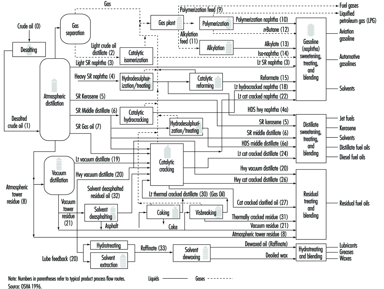
Separation. Crude oil is physically separated by fractionation in atmospheric and vacuum distillation towers, into groups of hydrocarbon molecules with various boiling-point ranges, called “fractions” or “cuts”.
Conversion. Conversion processes used to change the size and/or structure of hydrocarbon molecules include:
- decomposition (dividing) by hydro-, thermal and catalytic cracking, coking and visbreaking
- unification (combining) through alkylation and polymerization
- alteration (rearranging) with isomerization and catalytic reforming
- treatment.
Since the beginning of refining, various treatment methods have been used to remove non-hydrocarbons, impurities and other constituents that adversely affect the performance properties of finished products or reduce the efficiency of the conversion processes. Treatment involves both chemical reactions and physical separation, such as dissolving, absorption or precipitation, using a variety and combination of processes. Treatment methods include removing or separating aromatics and naphthenes, as well as removing impurities and undesirable contaminants. Sweetening compounds and acids are used to desulphurize crude oil before processing, and to treat products during and after processing. Other treatment methods include crude desalting, chemical sweetening, acid treating, clay contacting, hydrodesulphurizing, solvent refining, caustic washing, hydrotreating, drying, solvent extraction and solvent dewaxing.
Formulating and blending is the process of mixing and combining hydrocarbon fractions, additives and other components to produce finished products with specific desired performance properties.
Auxiliary refining operations. Other refinery operations which are required to support hydrocarbon processing include light ends recovery; sour water stripping; solid waste, waste water and process water treatment and cooling; hydrogen production; sulphur recovery; and acid and tail gas treatment. Other process functions are providing catalysts, reagents, steam, air, nitrogen, oxygen, hydrogen and fuel gases.
Refinery non-process facilities. All refineries have a multitude of facilities, functions, equipment and systems which support the hydrocarbon process operations. Typical support operations are heat and power generation; product movement; tank storage; shipping and handling; flares and relief systems; furnaces and heaters; alarms and sensors; and sampling, testing and inspecting. Non-process facilities and systems include firefighting, water and protection systems, noise and pollution controls, laboratories, control rooms, warehouses, maintenance and administrative facilities.
Major Products of Crude Oil Refining
Petroleum refining has evolved continuously in response to changing consumer demand for better and different products. The original process requirement was to produce kerosene as a cheaper and better source of fuel for lighting than whale oil. The development of the internal combustion engine led to the production of benzene, gasoline and diesel fuels. The evolution of the airplane created a need for high-octane aviation gasoline and jet fuel, which is a sophisticated form of the original refinery product, kerosene. Present-day refineries produce a variety of products, including many which are used as feedstocks for cracking processes and lubricant manufacturing, and for the petrochemical industry. These products can be broadly classified as fuels, petrochemical feedstocks, solvents, process oils, lubricants and special products such as wax, asphalt and coke. (See table 2.)
Table 2. Principal products of crude oil refining
|
Hydrocarbon gases |
Uses |
|
Liquified gases |
Cooking and industrial gas |
|
Chemical industry feedstock |
Rubber products |
|
Carbon black |
Printing inks |
|
Light distillates |
|
|
Light naphthas |
Olefins |
|
Intermediate naphthas |
Aviation and motor gasoline |
|
Heavy naphthas |
Military jet fuel |
|
Gas oil |
Cracking stock |
|
Heavy distillates |
|
|
Technical oils |
Textile oils |
|
Lubricating oils |
Transformer and spindle oils |
|
Paraffin wax |
Rubber industry |
|
Residues |
|
|
Petrolatum |
Petroleum jelly |
|
Residual fuel oil |
No. 6 boiler and process fuel oil |
|
Asphalts |
Paving asphalt |
|
Refinery by-products |
|
|
Coke |
Electrodes and fuel |
|
Sulphonates |
Emulsifiers |
|
Sulphuric acid |
Synthetic fertilizer |
|
Sulphur |
Chemicals |
|
Hydrogen |
Hydrocarbon reformation |
A number of chemicals are used in, or formed as a result of, hydrocarbon processing. A brief description of those which are specific and pertinent to refining follows:
Sulphur Dioxide
Flue gas from burning high-sulphur-content fuels usually contains high levels of sulphur dioxide, which usually is removed by water scrubbing.
Caustics
Caustics are added to desalting water to neutralize acids and reduce corrosion. Caustics are also added to desalted crude in order to reduce the amount of corrosive chlorides in the tower overheads. They are used in refinery treating processes to remove contaminants from hydrocarbon streams.
Nitrogen oxides and carbon monoxide
Flue gas contains up to 200 ppm of nitric oxide, which reacts slowly with oxygen to form nitrogen dioxide. Nitric oxide is not removed by water scrubbing, and nitrogen dioxide can dissolve in water to form nitrous and nitric acid. Flue gas normally contains only a slight amount of carbon monoxide, unless combustion is abnormal.
Hydrogen sulphide
Hydrogen sulphide is found naturally in most crude oils and is also formed during processing by the decomposition of unstable sulphur compounds. Hydrogen sulphide is an extremely toxic, colourless, flammable gas which is heavier than air and soluble in water. It has a rotten egg odour which is discernible at concentrations well below its very low exposure limit. This smell cannot be relied upon to provide adequate warning as the senses are almost immediately desensitized upon exposure. Special detectors are required to alert workers to the presence of hydrogen sulphide, and proper respiratory protection should be used in the presence of the gas. Exposure to low levels of hydrogen sulphide will cause irritation, dizziness and headaches, while exposure to levels in excess of the prescribed limits will cause nervous system depression and eventually death.
Sour water
Sour water is process water which contains hydrogen sulphide, ammonia, phenols, hydrocarbons and low-molecular-weight sulphur compounds. Sour water is produced by steam stripping hydrocarbon fractions during distillation, regenerating catalyst, or steam stripping hydrogen sulphide during hydrotreating and hydrofinishing. Sour water is also generated by the addition of water to processes to absorb hydrogen sulphide and ammonia.
Sulphuric acid and hydrofluoric acid
Sulphuric acid and hydrofluoric acid are used as catalysts in alkylation processes. Sulphuric acid is also used in some of the treatment processes.
Solid catalysts
A number of different solid catalysts in many forms and shapes, from pellets to granular beads to dusts, made of various materials and having various compositions, are used in refining processes. Extruded pellet catalysts are used in moving and fixed bed units, while fluid bed processes use fine, spherical particulate catalysts. Catalysts used in processes which remove sulphur are impregnated with cobalt, nickel or molybdenum. Cracking units use acid-function catalysts, such as natural clay, silica alumina and synthetic zeolites. Acid-function catalysts impregnated with platinum or other noble metals are used in isomerization and reforming. Used catalysts require special handling and protection from exposures, as they may contain metals, aromatic oils, carcinogenic polycyclic aromatic compounds or other hazardous materials, and may also be pyrophoric.
Fuels
The principal fuel products are liquefied petroleum gas, gasoline, kerosene, jet fuel, diesel fuel and heating oil and residual fuel oils.
Liquefied petroleum gas (LPG), which consists of mixtures of paraffinic and olefinic hydrocarbons such as propane and butane, is produced for use as a fuel, and is stored and handled as liquids under pressure. LPG has boiling points ranging from about –74 °C to
38 °C, is colourless, and the vapours are heavier than air and extremely flammable. The important qualities from an occupational health and safety perspective of LPGs are vapour pressure and control of contaminants.
Gasoline. The most important refinery product is motor gasoline, a blend of relatively low-boiling hydrocarbon fractions, including reformate, alkylate, aliphatic naphtha (light straight-run naphtha), aromatic naphtha (thermal and catalytic cracked naphtha) and additives. Gasoline blending stocks have boiling points which range from ambient temperatures to about 204 °C, and a flashpoint below –40 °C. The critical qualities for gasoline are octane number (anti-knock), volatility (starting and vapour lock) and vapour pressure (environmental control). Additives are used to enhance gasoline performance and provide protection against oxidation and rust formation. Aviation gasoline is a high-octane product, specially blended to perform well at high altitudes.
Tetra ethyl lead (TEL) and tetra methyl lead (TML) are gasoline additives which improve octane ratings and anti-knock performance. In an effort to reduce lead in automotive exhaust emissions, these additives are no longer in common use, except in aviation gasoline.
Ethyl tertiary butyl ether (ETBE), methyl tertiary butyl ether (MTBE), tertiary amyl methyl ether (TAME) and other oxygenated compounds are used in lieu of TEL and TML to improve unleaded gasoline anti-knock performance and reduce carbon monoxide emissions.
Jet fuel and kerosene. Kerosene is a mixture of paraffins and naphthenes with usually less than 20% aromatics. It has a flashpoint above 38 °C and a boiling range of 160 °C to 288 °C, and is used for lighting, heating, solvents and blending into diesel fuel. Jet fuel is a middle distillate kerosene product whose critical qualities are freezepoint, flashpoint and smokepoint. Commercial jet fuel has a boiling range of about 191 °C to 274 °C, and military jet fuel from 55 °C to 288 °C.
Distillate fuels. Diesel fuels and domestic heating oils are light-coloured mixtures of paraffins, naphthenes and aromatics, and may contain moderate quantities of olefins. Distillate fuels have flashpoints above 60 °C and boiling ranges of about 163 °C to 371 °C, and are often hydrodesulphurized for improved stability. Distillate fuels are combustible and when heated may emit vapours which can form ignitable mixtures with air. The desirable qualities required for distillate fuels include controlled flash- and pourpoints, clean burning, no deposit formation in storage tanks, and a proper diesel fuel cetane rating for good starting and combustion.
Residual fuels. Many ships and commercial and industrial facilities use residual fuels or combinations of residual and distillate fuels, for power, heat and processing. Residual fuels are dark- coloured, highly viscous liquid mixtures of large hydrocarbon molecules, with flashpoints above 121 °C and high boiling points. The critical specifications for residual fuels are viscosity and low sulphur content (for environmental control).
Health and safety considerations
The primary safety hazard of LPG and gasoline is fire. The high volatility and high flammability of the lower-boiling-point products allows vapours to evaporate readily into air and form flammable mixtures which can be easily ignited. This is a recognized hazard that requires specific storage, containment and handling precautions, and safety measures to assure that releases of vapours and sources of ignition are controlled so that fires do not occur. The less volatile fuels, such as kerosene and diesel fuel, should be handled carefully to prevent spills and possible ignition, as their vapours are also combustible when mixed with air in the flammable range. When working in atmospheres containing fuel vapours, concentrations of highly volatile, flammable product vapours in air are often restricted to no more than 10% of the lower flammable limits (LFL), and concentrations of less volatile, combustible product vapours to no more than 20% LFL, depending on applicable company and government regulations, in order to reduce the risk of ignition.
Although gasoline vapour levels in air mixtures are typically maintained below 10% of the LFL for safety purposes, this concentration is considerably above the exposure limits to be observed for health reasons. When inhaled, small amounts of gasoline vapour in air, well below the lower flammable limit, can cause irritation, headaches and dizziness, while inhalation of larger concentrations can cause loss of consciousness and eventually death. Long-term health effects may also be possible. Gasoline contains benzene, for example, a known carcinogen with allowable exposure limits of only a few parts per million. Therefore, even working in gasoline vapour atmospheres at levels below 10% LFL requires appropriate industrial hygiene precautions, such as respiratory protection or local exhaust ventilation.
In the past, many gasolines contained tetra-ethyl or tetra methyl alky lead anti-knock additives, which are toxic and present serious lead absorption hazards by skin contact or inhalation. Tanks or vessels which contained leaded gasoline at any time during their use must be vented, thoroughly cleaned, tested with a special “lead-in-air” test device and certified to be lead-free to assure that workers can enter without using self-contained or supplied breathing air equipment, even though oxygen levels are normal and the tanks now contain unleaded gasoline or other products.
Gaseous petroleum fractions and the more highly volatile fuel products have a mild anaesthetic effect, generally in inverse ratio to molecular weight. Lower-boiling-point liquid fuels, such as gasoline and kerosene, produce a severe chemical pneumonitis if inhaled, and should not be siphoned by mouth or accidentally ingested. Gases and vapours may also be present in sufficiently high concentrations to displace oxygen (in the air) below normal breathing levels. Maintaining vapour concentrations below the exposure limits and oxygen levels at normal breathing ranges, is usually accomplished by purging or ventilation.
Cracked distillates contain small amounts of carcinogenic polycyclic aromatic hydrocarbons (PAHs); therefore, exposure should be limited. Dermatitis may also develop from exposure to gasoline, kerosene and distillate fuels, as they have a tendency to defat the skin. Prevention is accomplished by use of personal protective equipment, barrier creams or reduced contact and good hygienic practices, such as washing with warm water and soap instead of cleaning hands with gasoline, kerosene or solvents. Some persons have skin sensitivity to the dyes used to colour gasoline and other distillate products.
Residual fuel oils contain traces of metals and may have entrained hydrogen sulphide, which is extremely toxic. Residual fuels which have high cracked stocks boiling above 370 °C contain carcinogenic PAHs. Repeated exposure to residual fuels without appropriate personal protection, should be avoided, especially when opening tanks and vessels, as hydrogen sulphide gas may be emitted.
Petrochemical feedstocks
Many products derived from crude-oil refining, such as ethylene, propylene and butadiene, are olefinic hydrocarbons derived from refinery cracking processes, and are intended for use in the petrochemical industry as feedstocks for the production of plastics, ammonia, synthetic rubber, glycol and so on.
Petroleum solvents
A variety of pure compounds, including benzene, toluene, xylene, hexane and heptane, whose boiling points and hydrocarbon composition are closely controlled, are produced for use as solvents. Solvents may be classified as aromatic or non-aromatic, depending on their composition. Their use as paint thinners, dry-cleaning fluids, degreasers, industrial and pesticide solvents and so on, is generally determined by their flashpoints, which vary from well below –18 °C to above 60 °C.
The hazards associated with solvents are similar to those of fuels in that the lower flashpoint solvents are flammable and their vapours, when mixed with air in the flammable range, are ignitable. Aromatic solvents will usually have more toxicity than non-aromatic solvents.
Process oils
Process oils include the high boiling range, straight run atmospheric or vacuum distillate streams and those which are produced by catalytic or thermal cracking. These complex mixtures, which contain large paraffinic, naphthenic and aromatic hydrocarbon molecules with more than 15 carbon atoms, are used as feedstocks for cracking or lubricant manufacturing. Process oils have fairly high viscosities, boiling points ranging from 260 °C to 538 °C, and flashpoints above 121 °C.
Process oils are irritating to the skin and contain high concentrations of PAHs as well as sulphur, nitrogen and oxygen compounds. Inhalation of vapours and mists should be avoided, and skin exposure should be controlled by the use of personal protection and good hygienic practices.
Lubricants and greases
Lubricating oil base stocks are produced by special refining processes to meet specific consumer requirements. Lubricating base stocks are light- to medium-coloured, low-volatile, medium- to high-viscous mixtures of paraffinic, naphthenic and aromatic oils, with boiling ranges from 371 °C to 538 °C. Additives, such as demulsifiers, anti-oxidants and viscosity improvers, are blended into the lubricating oil base stocks to provide the characteristics required for motor oils, turbine and hydraulic oils, industrial greases, lubricants, gear oils and cutting oils. The most critical quality for lubricating oil base stock is a high viscosity index, providing for less change in viscosity under varying temperatures. This characteristic may be present in the crude oil feed stock or attained through the use of viscosity index improver additives. Detergents are added to keep in suspension any sludge formed during the use of the oil.
Greases are mixtures of lubricating oils and metallic soaps, with the addition of special-purpose materials such as asbestos, graphite, molybdenum, silicones and talc to provide insulation or lubricity. Cutting and metal-process oils are lubricating oils with special additives such as chlorine, sulphur and fatty-acid additives which react under heat to provide lubrication and protection to the cutting tools. Emulsifiers and bacteria prevention agents are added to water-soluble cutting oils.
Although lubricating oils by themselves are non-irritating and have little toxicity, hazards may be presented by the additives. Users should consult supplier material safety data information to determine the hazards of specific additives, lubricants, cutting oils and greases. The primary lubricant hazard is dermatitis, which can usually be controlled by the use of personal protective equipment together with proper hygienic practices. Occasionally workers may develop a sensitivity to cutting oils or lubricants which will require reassignment to a job where contact cannot occur. There are some concerns about carcinogenic exposure to mists from naphthenic-based cutting and light spindle oils, which can be controlled by substitution, engineering controls or personal protection. The hazards of exposure to grease are similar to those of lubricating oil, with the addition of any hazards presented by the grease materials or additives. Most of these hazards are discussed elsewhere in this Encyclopaedia.
Special products
Wax is used for protecting food products; in coatings; as an ingredient in other products such as cosmetics and shoe polish and for candles.
Sulphur is produced as a result of petroleum refining. It is stored either as a heated, molten liquid in closed tanks or as a solid in containers or outdoors.
Coke is almost pure carbon, with a variety of uses from electrodes to charcoal briquettes, depending on its physical characteristics, which result from the coking process.
Asphalt, which is primarily used for paving roads and roofing materials, should be inert to most chemicals and weather conditions.
Waxes and asphalts are solid at ambient temperatures, and higher temperatures are needed for storage, handling and transportation, with the resulting hazard of burns. Petroleum wax is so highly refined that it usually does not present any hazards. Skin contact with wax can lead to plugging of pores, which can be controlled by proper hygienic practices. Exposure to hydrogen sulphide when asphalt and molten sulphur tanks are opened can be controlled by the use of appropriate engineering controls or respiratory protection. Sulphur is also readily ignitable at elevated temperatures. Asphalt is discussed elsewhere in the Encyclopaedia.
Petroleum Refining Processes
Hydrocarbon refining is the use of chemicals, catalysts, heat and pressure to separate and combine the basic types of hydrocarbon molecules naturally found in crude oil into groups of similar molecules. The refining process also rearranges the structures and bonding patterns of the basic molecules into different, more desirable hydrocarbon molecules and compounds. The type of hydrocarbon (paraffinic, naphthenic or aromatic) rather than the specific chemical compounds present, is the most significant factor in the refining process.
Throughout the refinery, operations procedures, safe work practices and the use of appropriate personal protective clothing and equipment, including approved respiratory protection, is needed for fire, chemical, particulate, heat and noise exposures and during process operations, sampling, inspection, turnaround and maintenance activities. As most refinery processes are continuous and the process streams are contained in enclosed vessels and piping, there is limited potential for exposure. However, the potential for fire exists because even though refinery operations are closed processes, if a leak or release of hydrocarbon liquid, vapour or gas occurs, the heaters, furnaces and heat exchangers throughout the process units are sources of ignition.
Crude oil pretreatment
Desalting
Crude oil often contains water, inorganic salts, suspended solids and water-soluble trace metals. The first step in the refining process is to remove these contaminants by desalting (dehydration) in order to reduce corrosion, plugging and fouling of equipment, and to prevent poisoning the catalysts in processing units. Chemical desalting, electrostatic separation and filtering are three typical methods of crude-oil desalting. In chemical desalting, water and chemical surfactants (demulsifiers) are added to the crude oil, heated so that salts and other impurities dissolve into the water or attach to the water, and are then held in a tank where they settle out. Electrical desalting applies high-voltage electrostatic charges in order to concentrate suspended water globules in the bottom portion of the settling tank. Surfactants are added only when the crude oil has a large amount of suspended solids. A third, less common process involves filtering heated crude oil using diatomaceous earth as a filtration medium.
In chemical and electrostatic desalting, the crude feedstock is heated to between 66 °C and 177 °C, to reduce viscosity and surface tension for easier mixing and separation of the water. The temperature is limited by the vapour pressure of the crude-oil feedstock. Both methods of desalting are continuous. Caustic or acid may be added to adjust the pH of the water wash, and ammonia added to reduce corrosion. Waste water, together with contaminants, is discharged from the bottom of the settling tank to the waste water treatment facility. The desalted crude oil is continuously drawn from the top of the settling tanks and sent to an atmospheric crude distillation (fractionating) tower. (See figure 2.)
Figure 2. Desalting (pre-treatment) process
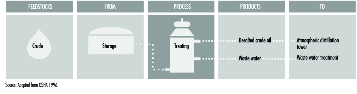
Inadequate desalting causes fouling of heater tubes and heat exchangers in all refinery process units, restricting product flow and heat transfer, and resulting in failures due to increased pressures and temperatures. Overpressuring the desalting unit will cause failure.
Corrosion, which occurs due to the presence of hydrogen sulphide, hydrogen chloride, naphthenic (organic) acids and other contaminants in the crude oil, also causes equipment failure. Corrosion occurs when neutralized salts (ammonium chlorides and sulphides) are moistened by condensed water. Because desalting is a closed process, there is little potential for exposure to crude oil or process chemicals, unless a leak or release occurs. A fire may occur as a result of a leak in the heaters, allowing a release of low-boiling-point components of crude oil.
There is the possibility of exposure to ammonia, dry chemical demulsifiers, caustics and/or acids during desalting. Where elevated operating temperatures are used when desalting sour crude oils, hydrogen sulphide will be present. Depending on the crude feedstock and the treatment chemicals used, the waste water will contain varying amounts of chlorides, sulphides, bicarbonates, ammonia, hydrocarbons, phenol and suspended solids. If diatomaceous earth is used in filtration, exposures should be minimized or controlled since diatomaceous earth can contain silica with a very fine particle size, making it a potential respiratory hazard.
Crude oil separation processes
The first step in petroleum refining is the fractionation of crude oil in atmospheric and vacuum distillation towers. Heated crude oil is physically separated into various fractions, or straight-run cuts, differentiated by specific boiling-point ranges and classified, in order of decreasing volatility, as gases, light distillates, middle distillates, gas oils and residuum. Fractionation works because the gradation in temperature from the bottom to the top of the distillation tower causes the higher-boiling-point components to condense first, while the lower-boiling-point fractions rise higher in the tower before they condense. Within the tower, the rising vapours and the descending liquids (reflux) mix at levels where they have compositions in equilibrium with each other. Special trays are located at these levels (or stages) which remove a fraction of the liquid which condenses at each level. In a typical two-stage crude unit, the atmospheric tower, producing light fractions and distillate, is immediately followed by a vacuum tower which processes the atmospheric residuals. After distillation, only a few hydrocarbons are suitable for use as finished products without further processing.
Atmospheric distillation
In atmospheric distillation towers, the desalted crude feedstock is preheated using recovered process heat. It then flows to a direct-fired crude charge heater, where it is fed into the vertical distillation column just above the bottom at pressures slightly above atmosphere and at temperatures from 343 °C to 371 °C, to avoid undesirable thermal cracking at higher temperatures. The lighter (lower boiling point) fractions diffuse into the upper part of the tower, and are continuously drawn off and directed to other units for further processing, treating, blending and distribution.
Fractions with the lowest boiling points, such as fuel gas and light naphtha, are removed from the top of the tower by an overhead line as vapours. Naphtha, or straight-run gasoline, is taken from the upper section of the tower as an overhead stream. These products are used as petrochemical and reformer feedstocks, gasoline blending stocks, solvents and LPGs.
Intermediate boiling range fractions, including gas oil, heavy naphtha and distillates, are removed from the middle section of the tower as side streams. These are sent to finishing operations for use as kerosene, diesel fuel, fuel oil, jet fuel, catalytic cracker feedstock and blending stocks. Some of these liquid fractions are stripped of their lighter ends, which are returned to the tower as downflowing reflux streams.
The heavier, higher-boiling-point fractions (called residuum, bottoms or topped crude) which condense or remain at the bottom of the tower, are used for fuel oil, bitumen manufacturing or cracking feedstock, or are directed to a heater and into the vacuum distillation tower for further fractionation. (See figure 3 and figure 4.)
Figure 3. Atmospheric distillation process

Figure 4. Schematic of atmospheric distrillation process
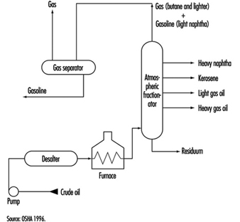
Vacuum distillation
Vacuum distillation towers provide the reduced pressure required to prevent thermal cracking when distilling the residuum, or topped crude, from the atmospheric tower at higher temperatures. The internal designs of some vacuum towers are different from atmospheric towers in that random packing and demister pads are used instead of trays. Larger diameter towers may also be used to keep velocities lower. A typical first-phase vacuum tower may produce gas oils, lubricating oil base stocks and heavy residual for propane deasphalting. A second-phase tower, operating at a lower vacuum, distills surplus residuum from the atmospheric tower which is not used for lube stock processing, and surplus residuum from the first vacuum tower not used for deasphalting.
Vacuum towers are typically used to separate catalytic cracker feedstocks from surplus residuum. Vacuum tower bottoms may also be sent to a coker, used as lubricant or asphalt stock or desulphurized and blended into low-sulphur fuel oil. (See figure 5 and figure 6.)
Figure 5. Vacuum distillation process
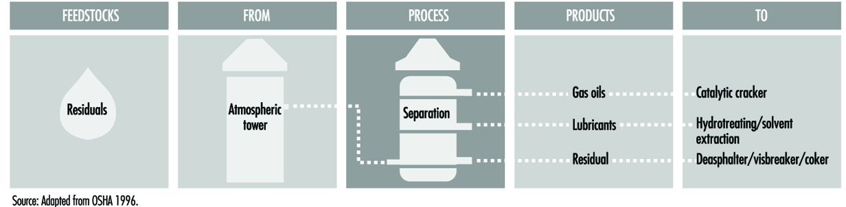
Figure 6. Schematic of vacuum distillation process
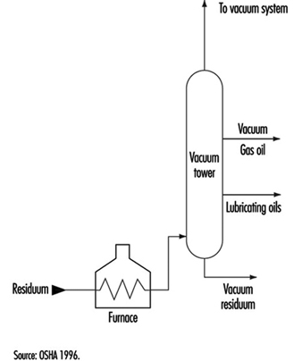
Distillation columns
Within refineries there are numerous other smaller distillation towers, called columns, designed to separate specific and unique products, which all work on the same principles as atmospheric towers. For example, a depropanizer is a small column designed to separate propane from isobutane and heavier components. Another larger column is used to separate ethyl benzene and xylene. Small “bubbler” towers, called strippers, use steam to remove trace amounts of light products (gasoline) from heavier product streams.
Control temperatures, pressures and reflux must be maintained within operating parameters to prevent thermal cracking from taking place within distillation towers. Relief systems are provided because excursions in pressure, temperature or liquid levels may occur if automatic control devices fail. Operations are monitored in order to prevent crude from entering the reformer charge. Crude feedstocks may contain appreciable amounts of water in suspension which separate during start-up and, along with water remaining in the tower from steam purging, settle in the bottom of the tower. This water may heat to the boiling point and create an instantaneous vaporization explosion upon contact with the oil in the unit.
The preheat exchanger, preheat furnace and bottoms exchanger, atmospheric tower and vacuum furnace, vacuum tower and overhead are susceptible to corrosion from hydrochloric acid (HCl), hydrogen sulphide (H2S), water, sulphur compounds and organic acids. When processing sour crudes, severe corrosion can occur in both atmospheric and vacuum towers where metal temperatures exceed 232 °C, and in furnace tubing. Wet H2S will also cause cracks in steel. When processing high-nitrogen crudes, nitrogen oxides, which are corrosive to steel when cooled to low temperatures in the presence of water, form in the flue gases of furnaces.
Chemicals are used to control corrosion by hydrochloric acid produced in distillation units. Ammonia may be injected into the overhead stream prior to initial condensation, and/or an alkaline solution may be carefully injected into the hot crude oil feed. If sufficient wash water is not injected, deposits of ammonium chloride can form, causing serious corrosion.
Atmospheric and vacuum distillation are closed processes, and exposures are minimal. When sour (high sulphur) crudes are processed, there may be potential exposure to hydrogen sulphide in the preheat exchanger and furnace, tower flash zone and overhead system, vacuum furnace and tower, and bottoms exchanger. Crude oils and distillation products all contain high-boiling aromatic compounds, including carcinogenic PAHs. Short-term exposure to high concentrations of naphtha vapour can result in headaches, nausea and dizziness, and long-term exposure can result in loss of consciousness. Benzene is present in aromatic naphthas, and exposure must be limited. The dehexanizer overhead may contain large amounts of normal hexane, which can affect the nervous system. Hydrogen chloride may be present in the preheat exchanger, tower top zones and overheads. Waste water may contain water-soluble sulphides in high concentrations and other water-soluble compounds, such as ammonia, chlorides, phenol and mercaptan, depending upon the crude feedstock and the treatment chemicals.
Crude oil conversion processes
Conversion processes, such as cracking, combining and rearranging, change the size and structure of hydrocarbon molecules in order to convert fractions into more desirable products. (See table 3.)
Table 3. Overview of petroleum refining processes
|
Process name |
Action |
Method |
Purpose |
Feedstocks |
Products |
|
Fractionation processes |
|||||
|
Atmospheric distillation |
Separation |
Thermal |
Separate fractions |
Desalted crude oil |
Gas, gas oil, distillate, residual |
|
Vacuum distillation |
Separation |
Thermal |
Separate without cracking |
Atmospheric tower residual |
Gas oil, lube stock, residual |
|
Conversion processes—Decomposition |
|||||
|
Catalytic cracking |
Alteration |
Catalytic |
Upgrade gasoline |
Gas oil, coke distillate |
Gasoline, petrochemical feedstock |
|
Coking |
Polymerization |
Thermal |
Convert vacuum residuals |
Residual, heavy oil, tar |
Naphtha, gas oil, coke |
|
Hydrocracking |
Hydrogenation |
Catalytic |
Convert to lighter hydrocarbons |
Gas oil, cracked oil, residuals |
Lighter, higher quality products |
|
Hydrogen steam reforming |
Decomposition |
Thermal/catalytic |
Produce hydrogen |
Desulphurized gas, O2 ,steam |
Hydrogen, CO,CO2 |
|
Steam cracking |
Decomposition |
Thermal |
Crack large molecules |
Atmospheric tower heavy fuel/distillate |
Cracked naphtha, coke, residuals |
|
Visbreaking |
Decomposition |
Thermal |
Reduce viscosity |
Atmospheric tower residual |
Distillate, car |
|
Conversion processes—Unification |
|||||
|
Alkylation |
Combining |
Catalytic |
Unite olefins and isoparaffins |
Tower isobutane/cracker olefin |
Iso-octane (alkylate) |
|
Grease compounding |
Combining |
Thermal |
Combine soaps and oils |
Lube oil, catty acid, alkymetal |
Lubricating grease |
|
Polymerization |
Polymerization |
Catalytic |
Unite two or more olefins |
Cracker olefins |
High octane naphtha, petrochemical stocks |
|
Conversion processes—Alteration/rearrangement |
|||||
|
Catalytic reforming |
Alteration/ |
Catalytic |
Upgrade low-octane naphtha |
Coker/hydrocracker naphtha |
High-octane reformate/aromatic |
|
Isomerization |
Rearrangement |
Catalytic |
Convert straight chain to branch |
Butane, centane, cexane |
Isobutane/pentane/hexane |
|
Treatment processes |
|||||
|
Amine treating |
Treatment |
Absorption |
Remove acidic contaminants |
Sour gas, cydrocarbons with CO2 and H2S |
Acid-free gases and liquid hydrocarbons |
|
Desalting (pre-treatment) |
Dehydration |
Absorption |
Remove contaminants |
Crude oil |
Desalted crude oil |
|
Drying and sweetening |
Treatment |
Absorption/thermal |
Remove H2O and sulphur compounds |
Liquid hydrocarbon, LPG, alkylated feedstock |
Sweet and dry hydrocarbons |
|
Furfural extraction |
Solvent extraction |
Absorption |
Upgrade middistillate and lubes |
Cycle oils and lube feedstocks |
High-quality diesel and lube oil |
|
Hydrodesulphurization |
Treatment |
Catalytic |
Remove sulphur, contaminants |
High-sulphur residual/gas oil |
Desulphurized olefins |
|
Hydrotreating |
Hydrogenation |
Catalytic |
Remove impurities/ saturate hydrocarbons |
Residuals, cracked hydrocarbons |
Cracker feed, cistillate, lube |
|
Phenol extraction |
Solvent extraction |
Absorption/thermal |
Improve lube viscosity index, colour |
Lube oil base stocks |
High-quality lube oils |
|
Solvent deasphalting |
Treatment |
Absorption |
Remove asphalt |
Vacuum tower residual, cropane |
Heavy lube oil, csphalt |
|
Solvent dewaxing |
Treatment |
Cool/filter |
Remove wax from lube stocks |
Vacuum tower lube oils |
Dewaxed lube base stock |
|
Solvent extraction |
Solvent extraction |
Absorption/ |
Separate unsaturated aromatics |
Gas oil, ceformate, cistillate |
High-octane gasoline |
|
Sweetening |
Treatment |
Catalytic |
Remove H2S, convert mercaptan |
Untreated distillate/gasoline |
High-quality distillate/gasoline |
A number of hydrocarbon molecules not normally found in crude oil but important to the refining process are created as a result of conversion. Olefins (alkenes, di-olefins and alkynes) are unsaturated chain- or ring-type hydrocarbon molecules with at least one double bond. They are usually formed by thermal and catalytic cracking and rarely occur naturally in unprocessed crude oil.
Alkenes are straight-chain molecules with the formula CnHn containing at least one double bond (unsaturated) linkage in the chain. The simplest alkene molecule is the mono-olefin ethylene, with two carbon atoms, joined by a double bond, and four hydrogen atoms. Di-olefins (containing two double bonds), such as 1,2-butadiene and 1,3-butadiene, and alkynes (containing a triple bond), such as acetylene, occur in C5 and lighter fractions from cracking. Olefins are more reactive than paraffins or naphthenes, and readily combine with other elements such as hydrogen, chlorine and bromine.
Cracking processes
Following distillation, subsequent refinery processes are used to alter the molecular structures of the fractions to create more desirable products. One of these processes, cracking, breaks (or cracks) heavier, higher-boiling-point petroleum fractions into more valuable products such as gaseous hydrocarbons, gasoline blending stocks, gas oil and fuel oil. During the process, some of the molecules combine (polymerize) to form larger molecules. The basic types of cracking are thermal cracking, catalytic cracking and hydro-cracking.
Thermal cracking processes
Thermal cracking processes, developed in 1913, heat distillate fuels and heavy oils under pressure in large drums until they crack (divide) into smaller molecules with better anti-knock characteristics. This early method, which produced large amounts of solid, unwanted coke, has evolved into modern thermal cracking processes including visbreaking, steam cracking and coking.
Visbreaking
Visbreaking is a mild form of thermal cracking which reduces the pour point of waxy residues and significantly lowers the viscosity of feedstock without affecting its boiling-point range. Residual from the atmospheric distillation tower is mildly cracked in a heater at atmospheric pressure. It is then quenched with cool gas oil to control overcracking, and flashed in a distillation tower. The thermally cracked residue tar, which accumulates in the bottom of the fractionation tower, is vacuum flashed in a stripper and the distillate is recycled. (See figure 7.)
Figure 7. Visbreaking process
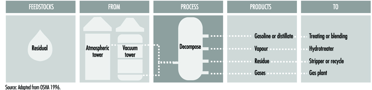
Steam cracking
Steam cracking produces olefins by thermally cracking large hydrocarbon molecule feedstocks at pressures slightly above atmospheric and at very high temperatures. Residual from steam cracking is blended into heavy fuels. Naphtha produced from steam cracking usually contains benzene, which is extracted prior to hydrotreating.
Coking
Coking is a severe form of thermal cracking used to obtain straight-run gasoline (coker naphtha) and various middle distillate fractions used as catalytic cracking feedstocks. This process so completely reduces hydrogen from the hydrocarbon molecule, that the residue is a form of almost pure carbon called coke. The two most common coking processes are delayed coking and continuous (contact or fluid) coking, which, depending upon the reaction mechanism, time, temperature and the crude feedstock, produce three types of coke—sponge, honeycomb and needle coke. (See figure 8.)
Figure 8. Coking process

- Delayed coking. In delayed coking, the feedstock is first charged to a fractionator to separate lighter hydrocarbons, and then combined with heavy recycle oil. The heavy feedstock is fed to the coker furnace and heated to high temperatures at low pressures to prevent premature coking in the heater tubes, producing partial vaporization and mild cracking. The liquid/vapour mixture is pumped from the heater to one or more coker drums, where the hot material is held approximately 24 hours (delayed) at low pressures until it cracks into lighter products. After the coke reaches a predetermined level in one drum, the flow is diverted to another drum to maintain continuous operation. Vapour from the drums is returned to the fractionator to separate out gas, naphtha and gas oils, and to recycle heavier hydrocarbons through the furnace. The full drum is steamed to strip out uncracked hydrocarbons, cooled by water injection and decoked mechanically by an auger rising from the bottom of the drum, or hydraulically by fracturing the coke bed with high-pressure water ejected from a rotating cutter.
- Continuous coking. Continuous (contact or fluid) coking is a moving bed process which operates at lower pressures and higher temperatures than delayed coking. In continuous coking, thermal cracking occurs by using heat transferred from hot recycled coke particles to feedstock in a radial mixer, called a reactor. Gases and vapours are taken from the reactor, quenched to stop further reaction and fractionated. The reacted coke enters a surge drum and is lifted to a feeder and classifier where the larger coke particles are removed. The remaining coke is dropped into the reactor preheater for recycling with feedstock. The process is automatic in that there is a continuous flow of coke and feedstock, and coking occurs both in the reactor and in the surge drum.
Health and safety considerations
In coking, temperature control should be held within a close range, as high temperatures will produce coke which is too hard to cut out of the drum. Conversely, temperatures which are too low will result in a high asphaltic content slurry. Should coking temperatures get out of control, an exothermic reaction could occur.
In thermal cracking when sour crudes are processed, corrosion can occur where metal temperatures are between 232 °C and 482 °C. It appears that coke forms a protective layer on the metal above 482 °C. However, hydrogen sulphide corrosion occurs when temperatures are not properly controlled above 482 °C. The lower part of the tower, high temperature exchangers, furnace and soaking drums are subject to corrosion. Continuous thermal changes cause coke drum shells to bulge and crack.
Water or steam injection is used to prevent buildup of coke in delayed coker furnace tubes. Water must be completely drained from the coker, so as not to cause an explosion upon recharging with hot coke. In emergencies, alternate means of egress from the working platform on top of coke drums is needed.
Burns may occur when handling hot coke, from steam in the event of a steam line leak, or from hot water, hot coke or hot slurry which may be expelled when opening cokers. The potential exists for exposure to aromatic naphthas containing benzene, hydrogen sulphide and carbon monoxide gases, and to trace amounts of carcinogenic PAHs associated with coking operations. Waste sour water may be highly alkaline, and contain oil, sulphides, ammonia and phenol. When coke is moved as a slurry, oxygen depletion may occur within confined spaces such as storage silos, because wet carbon adsorbs oxygen.
Catalytic cracking processes
Catalytic cracking breaks up complex hydrocarbons into simpler molecules in order to increase the quality and quantity of lighter, more desirable products and decrease the amount of residuals. Heavy hydrocarbons are exposed at high temperature and low pressure to catalysts which promote chemical reactions. This process rearranges the molecular structure, converting heavy hydrocarbon feedstocks into lighter fractions such as kerosene, gasoline, LPG, heating oil and petrochemical feedstocks (see figure 9 and figure 10). Selection of a catalyst depends upon a combination of the greatest possible reactivity and the best resistance to attrition. The catalysts used in refinery cracking units are typically solid materials (zeolite, aluminium hydrosilicate, treated bentonite clay, Fuller’s earth, bauxite and silica-alumina) which are in the form of powders, beads, pellets or shaped materials called extrudites.
Figure 9. Catalytic cracking process
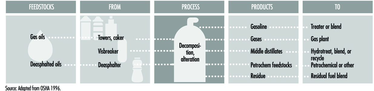
Figure 10. Schematic of catalytic cracking process
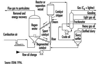
There are three basic functions in all catalytic cracking processes:
- Reaction—feedstock reacts with catalyst and cracks into different hydrocarbons.
- Regeneration—catalyst is reactivated by burning off coke.
- Fractionation—cracked hydrocarbon stream is separated into various products.
Catalytic cracking processes are very flexible and operating parameters can be adjusted to meet changing product demand. The three basic types of catalytic cracking processes are:
- fluid catalytic cracking (FCC)
- moving bed catalytic cracking
- thermofor catalytic cracking (TCC).
Fluid catalytic cracking
Fluid-bed catalytic crackers have a catalyst section (riser, reactor and regenerator) and a fractionating section, both operating together as an integrated processing unit. The FCC uses finely powdered catalyst, suspended in oil vapour or gas, which acts as a fluid. Cracking takes place in the feed pipe (riser) in which the mixture of catalyst and hydrocarbons flow through the reactor.
The FCC process mixes a preheated hydrocarbon charge with hot, regenerated catalyst as it enters the riser leading to the reactor. The charge combines with recycle oil within the riser, is vaporized and is raised to reactor temperature by the hot catalyst. As the mixture travels up the reactor, the charge is cracked at low pressure. This cracking continues until the oil vapours are separated from the catalyst in the reactor cyclones. The resultant product stream enters a column where it is separated into fractions, with some of the heavy oil directed back into the riser as recycle oil.
Spent catalyst is regenerated to remove coke which collects on the catalyst during the process. Spent catalyst flows through the catalyst stripper to the regenerator where it mixes with preheated air, burning off most of the coke deposits. Fresh catalyst is added and worn-out catalyst removed to optimize the cracking process.
Moving bed catalytic cracking
Moving-bed catalytic cracking is similar to fluid catalytic cracking; however, the catalyst is in the form of pellets instead of fine powder. The pellets move continuously by conveyor or pneumatic lift tubes to a storage hopper at the top of the unit, and then flow downward by gravity through the reactor to a regenerator. The regenerator and hopper are isolated from the reactor by steam seals. The cracked product is separated into recycle gas, oil, clarified oil, distillate, naphtha and wet gas.
Thermofor catalytic cracking
In thermofor catalytic cracking, the preheated feedstock flows by gravity through the catalytic reactor bed. Vapours are separated from the catalyst and sent to a fractionating tower. The spent catalyst is regenerated, cooled and recycled, and the flue gas from regeneration is sent to a carbon monoxide boiler for heat recovery.
Health and safety considerations
Regular sampling and testing of feedstock, product and recycle streams should be performed to assure that the cracking process is working as intended and that no contaminants have entered the process stream. Corrosives or deposits in feedstock can foul gas compressors. When processing sour crude, corrosion may be expected where temperatures are below
482 °C. Corrosion takes place where both liquid and vapour phases exist and at areas subject to local cooling, such as nozzles and platform supports. When processing high-nitrogen feedstocks, exposure to ammonia and cyanide may subject carbon steel equipment in the FCC overhead system to corrosion, cracking or hydrogen blistering, which can be minimized by water wash or by corrosion inhibitors. Water wash may be used to protect overhead condensers in the main column subjected to fouling from ammonium hydrosulphide.
Critical equipment, including pumps, compressors, furnaces and heat exchangers should be inspected. Inspections should include checking for leaks due to erosion or other malfunctions such as catalyst buildup on the expanders, coking in the overhead feeder lines from feedstock residues, and other unusual operating conditions.
Liquid hydrocarbons in the catalyst or entering the heated combustion air stream can cause exothermic reactions. In some processes, caution must be taken to assure that explosive concentrations of catalyst dust are not present during recharge or disposal. When unloading coked catalyst, the possibility of iron sulphide fires exists. Iron sulphide will ignite spontaneously when exposed to air, and therefore needs to be wetted down with water to prevent it from becoming a source of ignition for vapours. Coked catalyst may either be cooled to below 49 °C before dumping from the reactor, or first dumped into containers purged with inert nitrogen and then cooled before further handling.
The possibility of exposure to extremely hot hydrocarbon liquids or vapours is present during process sampling or if a leak or release occurs. In addition, exposure to carcinogenic PAHs, aromatic naphtha containing benzene, sour gas (fuel gas from processes such as catalytic cracking and hydrotreating, which contains hydrogen sulphide and carbon dioxide), hydrogen sulphide and/or carbon monoxide gas may occur during a release of product or vapour. Inadvertent formation of highly toxic nickel carbonyl may occur in cracking processes that use nickel catalysts with resultant potential for hazardous exposures.
Catalyst regeneration involves steam stripping and decoking, which results in potential exposure to fluid waste streams which may contain varying amounts of sour water, hydrocarbon, phenol, ammonia, hydrogen sulphide, mercaptan and other materials, depending upon the feedstocks, crudes and processes. Safe work practices and the use of appropriate personal protective equipment (PPE) are needed when handling spent catalyst, recharging catalyst, or if leaks or releases occur.
Hydrocracking process
Hydrocracking is a two-stage process combining catalytic cracking and hydrogenation, wherein distillate fractions are cracked in the presence of hydrogen and special catalysts to produce more desirable products. Hydrocracking has an advantage over catalytic cracking in that high-sulphur feedstocks can be processed without previous desulphurization. In the process, heavy aromatic feedstock is converted into lighter products under very high pressures and fairly high temperatures. When the feedstock has a high paraffinic content, the hydrogen prevents the formation of PAHs, reduces tar formation and prevents build-up of coke on the catalyst. Hydrocracking produces relatively large amounts of isobutane for alkylation feedstocks and also causes isomerization for pour point control and smoke point control, both of which are important in high-quality jet fuel.
In the first stage, feedstock is mixed with recycled hydrogen, heated and sent to the primary reactor, where a large amount of the feedstock is converted to middle distillates. Sulphur and nitrogen compounds are converted by a catalyst in the primary stage reactor to hydrogen sulphide and ammonia. The residual is heated and sent to a high-pressure separator, where hydrogen-rich gases are removed and recycled. The remaining hydrocarbons are stripped or purified to remove the hydrogen sulphide, ammonia and light gases, which are collected in an accumulator, where gasoline is separated from sour gas.
The stripped liquid hydrocarbons from the primary reactor are mixed with hydrogen and sent to the second-stage reactor, where they are cracked into high-quality gasoline, jet fuel and distillate blending stocks. These products go through a series of high- and low-pressure separators to remove gases, which are recycled. The liquid hydrocarbons are stabilized, split and stripped, with the light naphtha products from the hydrocracker used to blend gasoline while the heavier naphthas are recycled or sent to a catalytic reformer unit. (See figure 11.)
Figure 11. Hydrocracking process
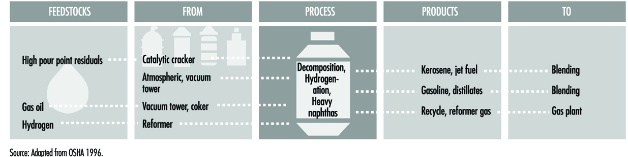
Health and safety considerations
Inspection and testing of safety relief devices are important due to the very high pressures in this process. Proper process control is needed to protect against plugging reactor beds. Because of the operating temperatures and presence of hydrogen, the hydrogen sulphide content of the feedstock must be strictly kept to a minimum in order to reduce the possibility of severe corrosion. Corrosion by wet carbon dioxide in areas of condensation must also be considered. When processing high-nitrogen feedstocks, the ammonia and hydrogen sulphide form ammonium hydrosulphide, which causes serious corrosion at temperatures below the water dew point. Ammonium hydrosulphide is also present in sour water stripping. Because the hydrocracker operates at very high pressures and temperatures, control of both hydrocarbon leaks and hydrogen releases is important to prevent fires.
Because this is a closed process, exposures are minimal under normal operating conditions. There is a potential for exposure to aliphatic naphtha containing benzene, carcinogenic PAHs, hydrocarbon gas and vapour emissions, hydrogen-rich gas and hydrogen sulphide gas as a result of high-pressure leaks. Large quantities of carbon monoxide may be released during catalyst regeneration and changeover. Catalyst steam stripping and regeneration creates waste streams containing sour water and ammonia. Safe work practices and appropriate personal protective equipment are needed when handling spent catalyst. In some processes, care is needed to assure that explosive concentrations of catalytic dust do not form during recharging. Unloading coked catalyst requires special precautions to prevent iron sulphideinduced fires. The coked catalyst should either be cooled to below 49 °C before dumping, or placed in nitrogen-inerted containers until cooled.
Combining processes
Two combining processes, polymerization and alkylation, are used to join together small hydrogen-deficient molecules, called olefins, recovered from thermal and catalytic cracking, in order to create more desirable gasoline blending stocks.
Polymerization
Polymerization is the process of combining two or more unsaturated organic molecules (olefins) to form a single, heavier molecule with the same elements in the same proportion as the original molecule. It converts gaseous olefins, such as ethylene, propylene and butylene converted by thermal and fluid cracking units, into heavier, more complex, higher-octane molecules, including naphtha and petrochemical feedstocks. The olefin feedstock is pretreated to remove sulphur compounds and other undesirables, and then passed over a phosphorus catalyst, usually a solid catalyst or liquid phosphoric acid, where an exothermic polymeric reaction occurs. This requires the use of cooling water and the injection of cold feedstock into the reactor to control temperatures at various pressures. Acid in the liquids is removed by caustic wash, the liquids are fractionated, and the acid catalyst is recycled. The vapour is fractionated to remove butanes and neutralized to remove traces of acid. (See figure 12.)
Figure 12. Polymerization process
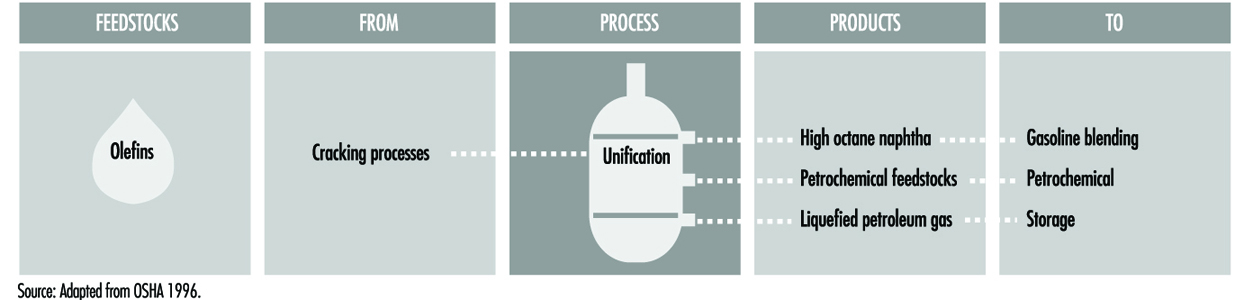
Severe corrosion, leading to equipment failure, will occur should water contact the phosphoric acid, such as during water washing at shutdowns. Corrosion may also occur in piping manifolds, reboilers, exchangers and other locations where acid may settle out. There is a potential for exposure to caustic wash (sodium hydroxide), to phosphoric acid used in the process or washed out during turnarounds, and to catalyst dust. The potential for an uncontrolled exothermic reaction exists should loss of cooling water occur.
Alkylation
Alkylation combines the molecules of olefins produced from catalytic cracking with those of isoparaffins in order to increase the volume and octane of gasoline blends. Olefins will react with isoparaffins in the presence of a highly active catalyst, usually sulphuric acid or hydrofluoric acid (or aluminium chloride) to create a long-branched-chain paraffinic molecule, called alkylate (iso-octane), with exceptional anti-knock quality. The alkylate is then separated and fractionated. The relatively low reaction temperatures of 10°C to 16°C for sulphuric acid, 27°C to 0°C for hydrofluoric acid (HF) and 0°C for aluminium chloride, are controlled and maintained by refrigeration. (See figure 13.)
Figure 13. Alkylation process
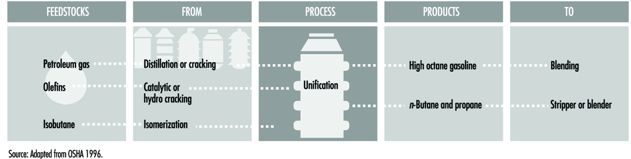
Sulphuric acid alkylation. In cascade-type sulphuric acid alkylation units, feedstocks, including propylene, butylene, amylene and fresh isobutane, enter the reactor, where they contact the sulphuric acid catalyst. The reactor is divided into zones, with olefins fed through distributors to each zone, and the sulphuric acid and isobutanes flowing over baffles from zone to zone. Reaction heat is removed by evaporation of isobutane. The isobutane gas is removed from the top of the reactor, cooled and recycled, with a portion directed to the depropanizer tower. Residual from the reactor is settled, and the sulphuric acid is removed from the bottom of the vessel and recirculated. Caustic and/or water scrubbers are used to remove small amounts of acid from the process stream, which then goes to a de-isobutanizer tower. The debutanizer isobutane overhead is recycled, and the remaining hydrocarbons are separated in a rerun tower and/or sent to blending.
Hydrofluoric acid alkylation. There are two types of hydrofluoric acid alkylation processes: Phillips and UOP. In the Phillips process, olefin and isobutane feedstock is dried and fed to a combination reactor/settler unit. The hydrocarbon from the settling zone is charged to the main fractionator. The main fractionator overhead goes to a depropanizer. Propane, with trace amounts of hydrofluoric acid (HF), goes to an HF stripper, and is then catalytically defluorinated, treated and sent to storage. Isobutane is withdrawn from the main fractionator and recycled to the reactor/settler, and alkylate from the bottom of the main fractionator is sent to a splitter.
The UOP process uses two reactors with separate settlers. Half of the dried feedstock is charged to the first reactor, along with recycle and make-up isobutane, and then to its settler, where the acid is recycled and the hydrocarbon charged to the second reactor. The other half of the feedstock goes to the second reactor, with the settler acid being recycled and the hydrocarbons charged to the main fractionator. Subsequent processing is similar to Phillips in that the overhead from the main fractionator goes to a depropanizer, isobutane is recycled and alkylate is sent to a splitter.
Health and safety considerations
Sulphuric acid and hydrofluoric acid are dangerous chemicals, and care during delivery and unloading of acid is essential. There is a need to maintain sulphuric acid concentrations of 85 to 95% for good operation and to minimize corrosion. To prevent corrosion from hydrofluoric acid, acid concentrations inside the process unit must be maintained above 65% and moisture below 4%. Some corrosion and fouling in sulphuric acid units occurs from the breakdown of sulphuric acid esters, or where caustic is added for neutralization. These esters can be removed by fresh-acid treating and hot-water washing.
Upsets can be caused by loss of the coolant water needed to maintain process temperatures. Pressure on the cooling water and steam side of exchangers should be kept below the minimum pressure on the acid service side to prevent water contamination. Vents can be routed to soda ash scrubbers to neutralize hydrogen fluoride gas or hydrofluoric acid vapours before release. Curbs, drainage and isolation may be provided for process unit containment so that effluent can be neutralized before release to the sewer system.
Hydrofluoric acid units should be thoroughly drained and chemically cleaned prior to turnarounds and entry, to remove all traces of iron fluoride and hydrofluoric acid. Following shutdown, where water has been used, the unit should be thoroughly dried before hydrofluoric acid is introduced. Leaks, spills or releases involving hydrofluoric acid, or hydrocarbons containing hydrofluoric acid, are extremely hazardous. Precautions are necessary to assure that equipment and materials which have been in contact with acid are handled carefully and are thoroughly cleaned before they leave the process area or refinery. Immersion wash vats are often provided for neutralization of equipment which has come into contact with hydrofluoric acid.
There is a potential for serious hazardous and toxic exposures should leaks, spills or releases occur. Direct contact with sulphuric or hydrofluoric acid will cause severe skin and eye damage, and inhalation of acid mists or hydrocarbon vapours containing acid will cause severe irritation and damage to the respiratory system. Special precautionary emergency preparedness measures should be used, and protection should be provided that is appropriate to the potential hazard and areas possibly affected. Safe work practices and appropriate skin and respiratory personal protective equipment are needed where potential exposures to hydrofluoric and sulphuric acids during normal operations exist, such as reading gauges, inspecting and process sampling, as well as during emergency response, maintenance and turnaround activities. Procedures should be in place to assure that protective equipment and clothing worn in sulphuric or hydrofluoric acid activities, including chemical protective suits, head and shoe coverings, gloves, face and eye protection and respiratory protective equipment, are thoroughly cleaned and decontaminated before reissue.
Rearranging processes
Catalytic reforming and isomerization are processes which rearrange hydrocarbon molecules to produce products with different characteristics. After cracking, some gasoline streams, although of the correct molecular size, require further processing to improve their performance, because they are deficient in some qualities, such as octane number or sulphur content. Hydrogen (steam) reforming produces additional hydrogen for use in hydrogenation processing.
Catalytic reforming
Catalytic reforming processes convert low-octane heavy naphthas into aromatic hydrocarbons for petrochemical feedstocks and high-octane gasoline components, called reformates, by molecular rearrangement or dehydrogenation. Depending on the feedstock and catalysts, reformates can be produced with very high concentrations of toluene, benzene, xylene and other aromatics useful in gasoline blending and petrochemical processing. Hydrogen, a significant by-product, is separated from the reformate for recycling and use in other processes. The resultant product depends on reactor temperature and pressure, the catalyst used and the hydrogen recycle rate. Some catalytic reformers operate at low pressure and others at high pressure. Some catalytic reforming systems continuously regenerate the catalyst, some facilities regenerate all of the reactors during turnarounds, and others take one reactor at a time off stream for catalyst regeneration.
In catalytic reforming, naphtha feedstock is pretreated with hydrogen to remove contaminants such as chlorine, sulphur and nitrogen compounds, which could poison the catalyst. The product is flashed and fractionated in towers where the remaining contaminants and gases are removed. The desulphurized naphtha feedstock is sent to the catalytic reformer, where it is heated to a vapour and passed through a reactor with a stationary bed of bi-metallic or metallic catalyst containing a small amount of platinum, molybdenum, rhenium or other noble metals. The two primary reactions which occur are production of high-octane aromatics by removing hydrogen from the feedstock molecules, and the conversion of normal paraffins to branched-chain or isoparaffins.
In platforming, another catalytic reforming process, feedstock which has not been hydrodesulphurized is combined with recycle gas and first passed over a less expensive catalyst. Any remaining impurities are converted to hydrogen sulphide and ammonia, and removed before the stream passes over the platinum catalyst. Hydrogen-rich vapour is recirculated to inhibit reactions which may poison the catalyst. The reactor output is separated into liquid reformate, which is sent to a stripping tower, and gas, which is compressed and recycled. (See figure 14.)
Figure 14. Catalytic reforming process
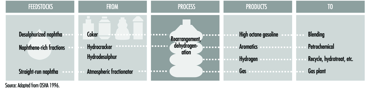
Operating procedures are needed to control hot spots during start-up. Care must be taken not to break or crush the catalyst when loading the beds, as small fines will plug up the reformer screens. Precautions against dust when regenerating or replacing catalyst are needed. Small emissions of carbon monoxide and hydrogen sulphide may occur during regeneration of catalyst.
Water wash should be considered where stabilizer fouling has occurred in reformers due to the formation of ammonium chloride and iron salts. Ammonium chloride may form in pretreater exchangers and cause corrosion and fouling. Hydrogen chloride, from the hydrogenation of chlorine compounds, may form acids or ammonium chloride salt. The potential exists for exposure to aliphatic and aromatic naphthas, hydrogen-rich process gas, hydrogen sulphide and benzene should a leak or release occur.
Isomerization
Isomerization converts n-butane, n-pentane and n-hexane into their respective iso-paraffins. Some of the normal straight-chain paraffin components of light straight-run naphtha are low in octane. These can be converted to high-octane, branched-chain isomers by rearranging the bonds between atoms, without changing the number or kinds of atoms. Isomerization is similar to catalytic reforming in that the hydrocarbon molecules are rearranged, but unlike catalytic reforming, isomerization just converts normal paraffins to iso-paraffins. Isomerization uses a different catalyst than catalytic reforming.
The two distinct isomerization processes are butane (C4) and pentane/hexane. (C5/C6).
Butane (C4) isomerization produces feedstock for alkylation. A lower-temperature process uses highly active aluminium chloride or hydrogen chloride catalyst without fired heaters, to isomerize n-butane. The treated and preheated feedstock is added to the recycle stream, mixed with HCl and passed through the reactor (see figure 15).
Figure 15. C4 isomerization
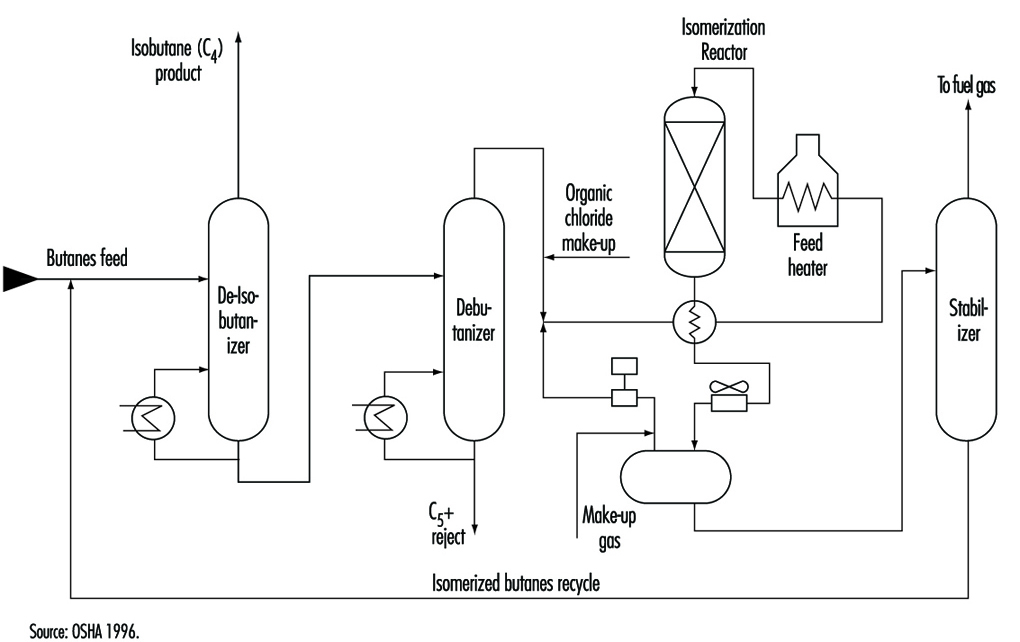
Pentane/hexane isomerization is used to increase the octane number by converting n-pentane and n-hexane. In a typical pentane/hexane isomerization process, dried and desulphurized feedstock is mixed with a small amount of organic chloride and recycled hydrogen, and heated to reactor temperature. It is then passed over supported-metal catalyst in the first reactor, where benzene and olefins are hydrogenated. The feed next goes to the isomerization reactor, where the paraffins are catalytically isomerized to isoparaffins, cooled and passed to a separator. Separator gas and hydrogen, with make-up hydrogen, is recycled. The liquid is neutralized with alkaline materials and sent to a stripper column, where hydrogen chloride is recovered and recycled. (See figure 16.)
Figure 16. Isomerization process
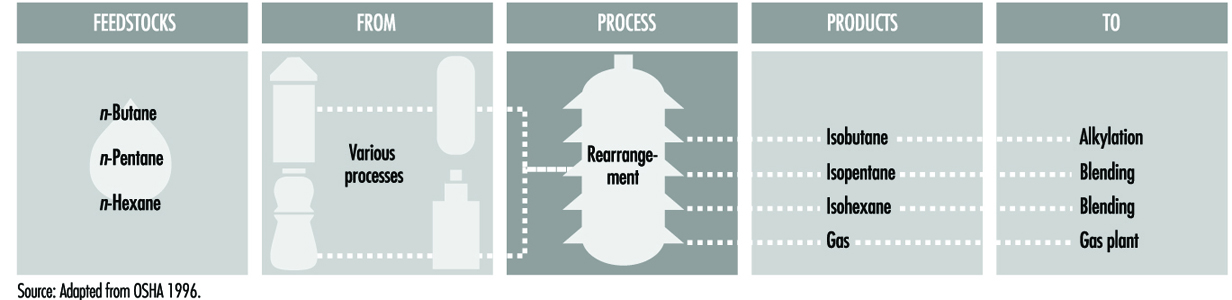
If the feedstock is not completely dried and desulphurized, the potential exists for acid formation, leading to catalyst poisoning and metal corrosion. Water or steam must not be allowed to enter areas where hydrogen chloride is present. Precautions are needed to prevent HCl from entering sewers and drains. There is a potential for exposure to isopentane and aliphatic naphtha vapours and liquid, as well as to hydrogen-rich process gas, hydrochloric acid and hydrogen chloride, and to dust when solid catalyst is used.
Hydrogen production (steam reforming)
High-purity hydrogen (95 to 99%) is needed for hydrodesulphurization, hydrogenation, hydrocracking and petrochemical processes. If not enough hydrogen is produced as by-products of refinery processes to meet the total refinery demand, the manufacture of additional hydrogen is required.
In hydrogen steam reforming, desulphurized gases are mixed with superheated steam and reformed in tubes containing a nickel base catalyst. The reformed gas, which consists of steam, hydrogen, carbon monoxide and carbon dioxide, is cooled and passed through converters where the carbon monoxide reacts with steam to form hydrogen and carbon dioxide. The carbon dioxide is scrubbed with amine solutions and vented to the atmosphere when the solutions are reactivated by heating. Any carbon monoxide remaining in the product stream is converted to methane. (See figure 17.)
Figure 17. Steam reforming process
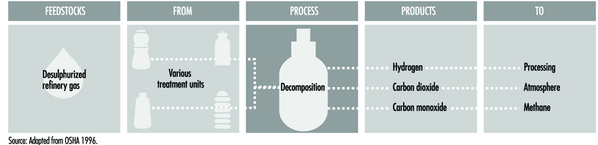
Inspections and testing must be conducted where the possibility exists for valve failure due to contaminants in the hydrogen. Carryover from caustic scrubbers to prevent corrosion in preheaters must be controlled and chlorides from the feedstock or steam system prevented from entering reformer tubes and contaminating the catalyst. Exposures can result from contamination of condensate by process materials such as caustics and amine compounds, and from excess hydrogen, carbon monoxide and carbon dioxide. The potential exists for burns from hot gases and superheated steam should a release occur.
Miscellaneous refinery processes
Lubricant base stock and wax processes
Lubricating oils and waxes are refined from various fractions of atmospheric and vacuum distillation. With the invention of vacuum distillation, it was discovered that the waxy residuum made a better lubricant than any of the animal fats that were then in use, which was the beginning of modern hydrocarbon lubricant refining technology, whose primary objective is to remove undesirable products, such as asphalts, sulphonated aromatics and paraffinic and iso-paraffinic waxes from the residual fractions in order to produce high-quality lubricants. This is done by a series of processes including de-asphalting, solvent extraction and separation and treatment processes such as dewaxing and hydrofinishing. (See figure 18)
Figure 18. Lubricating oil & wax manufacturing process
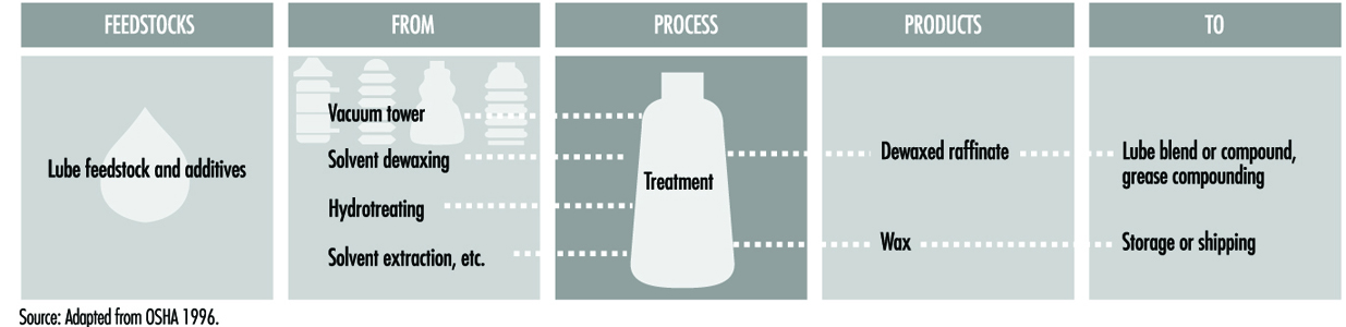
In extraction processing, reduced crude from the vacuum unit is propane de-asphalted and combined with straight-run lubricating-oil feedstock, preheated and solvent extracted to produce a feedstock called raffinate. In a typical extraction process which uses phenol as the solvent, the feedstock is mixed with phenol in the treating section at temperatures below 204 °C. Phenol is then separated from the raffinate and recycled. The raffinate may then be subjected to another extraction process which uses furfural to separate aromatic compounds from non-aromatic hydrocarbons, producing a lighter-coloured raffinate with improved viscosity index and oxidation and thermal stability.
Dewaxed raffinate may also be subject to further processing to improve the qualities of the base stock. Clay adsorbents are used to remove dark-coloured, unstable molecules from lubricating-oil base stocks. An alternate process, lube hydrofinishing, passes hot dewaxed raffinate and hydrogen through a catalyst that slightly changes the molecular structure, resulting in a lighter-coloured oil with improved characteristics. The treated lube oil base stocks are then mixed and/or compounded with additives to meet the required physical and chemical characteristics of motor oils, industrial lubricants and metal-working oils.
The two distinct types of wax derived from crude oil are paraffin wax, produced from distillate stocks, and microcrystalline wax, manufactured from residual stocks. Raffinate from the extraction unit contains a considerable amount of wax, which can be removed by solvent extraction and crystallization. The raffinate is mixed with a solvent, such as propane, methyl ethyl ketone (MEK) and toluene mixture or methyl isobutyl ketone (MIBK), and precooled in heat exchangers. The crystallization temperature is attained by the evaporation of the propane in the chiller and filter feed tanks. The wax is continuously removed by filters and cold solvent washed to recover retained oil. The solvent is recovered from the dewaxed raffinate by flashing and steam stripping, and recycled.
The wax is heated with hot solvent, chilled, filtered and given a final wash to remove all traces of oil. Before the wax is used, it may be hydro-finished to improve its odour and eliminate all traces of aromatics so the wax can be used in food processing. The dewaxed raffinate, which contains small amounts of paraffins, naphthenes and some aromatics, may be further processed for use as lubricating-oil base stocks.
Control of treater temperature is important to prevent corrosion from phenol. Wax can clog sewer or oil drainage systems and interfere with waste water treatment. The potential exists for exposure to process solvents such as phenol, propane, a methyl ethyl ketone and toluene mixture or methyl isobutyl ketone. Inhalation of hydrocarbon gases and vapours, aromatic naphtha containing benzene, hydrogen sulphide and hydrogen-rich process gas is a hazard.
Asphalt processing
After primary distillation operations, asphalt is a portion of residual matter which requires further processing to impart characteristics required by its final use. Asphalt for roofing materials is produced by air blowing. Residual is heated in a pipe still almost up to its flashpoint and charged to a blowing tower where hot air is injected for a predetermined period of time. The dehydrogen ation of the asphalt forms hydrogen sulphide, and the oxidation creates sulphur dioxide. Steam is used to blanket the top of the tower to entrain the contaminants, and is passed through a scrubber to condense the hydrocarbons.
Vacuum distillation is generally used to produce road tar asphalt. The residual is heated and charged to a column where vacuum is applied to prevent cracking.
Condensed steam from the various asphalt processes will contain trace amounts of hydrocarbons. Any disruption of the vacuum can result in the entry of atmospheric air and subsequent fire. In asphalt production, raising the temperature of the vacuum tower bottom to improve efficiency can generate methane by thermal cracking. This creates vapours in asphalt storage tanks which are in the flammable range, but not detectable by flash testing. Air blowing can create some polynuclear aromatics (i.e., PAHs). Condensed steam from the air blowing asphalt process may also contain various contaminants.
Hydrocarbon sweetening and treating processes
Many products, such as thermal naphthas from visbreaking, coking or thermal cracking, and high-sulphur naphthas and distillates from crude-oil distillation, require treating in order to be used in gasoline and fuel oil blends. Distillation products, including kerosene and other distillates, may contain trace amounts of aromatics, and naphthenes and lubricating-oil base stocks may contain wax. These undesirables are removed either at intermediate refining stages or just prior to sending products to blending and storage, by refining processes such as solvent extraction and solvent dewaxing. A variety of intermediate and finished products, including middle distillates, gasoline, kerosene, jet fuel and sour gases need to be dried and sweetened.
Treating is performed either at an intermediate stage in the refining process or just before sending finished products to blending and storage. Treating removes contaminants from oil, such as organic compounds containing sulphur, nitrogen and oxygen, dissolved metals, inorganic salts and soluble salts dissolved in emulsified water. Treating materials include acids, solvents, alkalis and oxidizing and adsorption agents. Acid treatments are used to improve the odour, colour and other properties of lube base stocks, to prevent corrosion and catalyst contamination, and to improve product stability. Hydrogen sulphide which is removed from “dry” sour gas by an absorbing agent (diethanolamine) is flared, used as a fuel or converted to sulphur. The type of treatment and agents depends on the crude feedstock, intermediate processes and end-product specifications.
Solvent treatment processes
Solvent extraction separates aromatics, naphthenes and impurities from product streams by dissolving or precipitation. Solvent extraction prevents corrosion, protects catalyst in subsequent processes and improves finished products by removing unsaturated, aromatic hydrocarbons from lubricant and grease base stocks.
The feedstock is dried and subjected to continuous countercurrent solvent treatment. In one process, feedstock is washed with a liquid in which the substances to be removed are more soluble than in the desired resultant product. In another process, selected solvents are added, causing impurities to precipitate out of the product. The solvent is separated from the product stream by heating, evaporation or fractionation, with residual trace amounts subsequently removed from the raffinate by steam stripping or vacuum flashing. Electric precipitation may be used for separation of inorganic compounds. The solvent is then regenerated to be used again in the process.
Typical chemicals used in the extraction process include a wide variety of acids, alkalis and solvents, including phenol and furfural, as well as oxidizing agents and adsorption agents. In the adsorption process, highly porous solid materials collect liquid molecules on their surfaces. The selection of specific processes and chemical agents depends on the nature of the feedstock being treated, the contaminants present and the finished product requirements. (See figure 19.)
Figure 19. Solvent extraction process
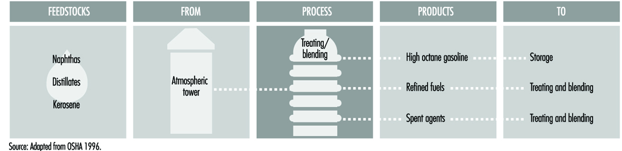
Solvent dewaxing removes wax from either distillate or residual base stocks, and may be applied at any stage in the refining process. In solvent dewaxing, waxy feedstocks are chilled by heat exchanger and refrigeration, and solvent is added to help develop crystals that are removed by vacuum filtration. The dewaxed oil and solvent are flashed and stripped, and the wax passes through a water settler, solvent fractionator and flash tower. (See figure 20.)
Figure 20. Solvent dewaxing process
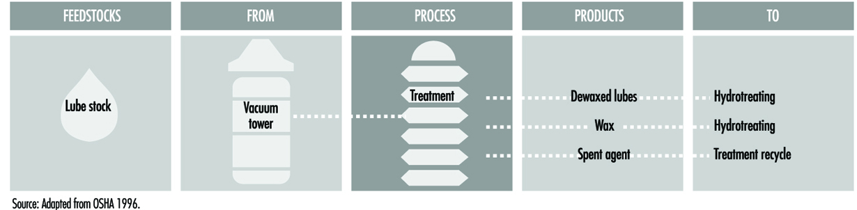
Solvent de-asphalting separates heavy oil fractions to produce heavy lubricating oil, catalytic cracking feedstock and asphalt. Feedstock and liquid propane (or hexane) are pumped to an extraction tower at precisely controlled mixtures, temperatures and pressures. Separation occurs in a rotating-disc contactor, based on differences in solubility. The products are then evaporated and steam stripped to recover propane for recycle. Solvent de-asphalting also removes sulphur and nitrogen compounds, metals, carbon residues and paraffins from feedstock. (See figure 21.)
Figure 21. Solvent de-asphalting process
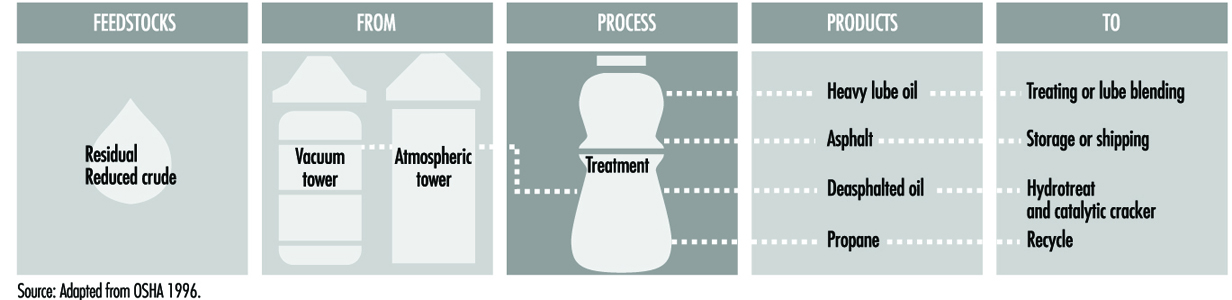
Health and safety considerations.
In solvent dewaxing, disruption of the vacuum will create a potential fire hazard by allowing air to enter the unit. The potential exists for exposure to dewaxing solvent vapours, a mixture of MEK and toluene. Although solvent extraction is a closed process, there is potential exposure to carcinogenic PAHs in the process oils and to extraction solvents such as phenol, furfural, glycol, MEK, amines and other process chemicals during handling and operations.
De-asphalting requires exact temperature and pressure control to avoid upset. In addition, moisture, excess solvent or a drop in operating temperature may cause foaming which affects the product temperature control and may create an upset. Contact with hot oil streams will cause skin burns. The potential exists for exposure to hot oil streams containing carcinogenic polycyclic aromatic compounds, liquefied propane and propane vapours, hydrogen sulphide and sulphur dioxide.
Hydrotreating processes
Hydrotreating is used to remove about 90% of contaminants, including nitrogen, sulphur, metals and unsaturated hydrocarbons (olefins), from liquid petroleum fractions such as straight-run gasoline. Hydrotreating is similar to hydrocracking in that both the hydrogen and the catalyst are used to enrich the hydrogen content of the olefin feedstock. However, the degree of saturation is not as great as that achieved in hydrocracking. Typically, hydrotreating is done prior to processes such as catalytic reforming, so that the catalyst is not contaminated by untreated feedstock. Hydrotreating is also used before catalytic cracking to reduce sulphur and improve product yields, and to upgrade middle distillate petroleum fractions into finished kerosene, diesel fuel and heating fuel oils.
Hydrotreating processes differ depending upon the feedstocks and catalysts. Hydrodesulphurization removes sulphur from kerosene, reduces aromatics and gum-forming characteristics, and saturates any olefins. Hydroforming is a dehydrogenation process used to recover excess hydrogen and produce high-octane gasoline. Hydrotreated products are blended or used as catalytic reforming feedstock.
In catalytic hydrodesulphurization, the feedstock is de-aerated, mixed with hydrogen, preheated and charged under high pressure through a fixed-bed catalytic reactor. The hydrogen is separated and recycled and the product stabilized in a stripper column where the light ends are removed.
During this process, sulphur and nitrogen compounds present in the feedstock are converted to hydrogen sulphide (H2S) and ammonia (NH3). Residual hydrogen sulphide and ammonia are removed either by steam stripping, by a combination high- and low-pressure separator or by amine wash which recovers hydrogen sulphide in a highly concentrated stream suitable for conversion into elemental sulphur. (See figure 22 and figure 23.)
Figure 22. Hydrodesulphurization process
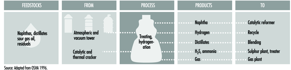
Figure 23. Schematic of hydrodesulphurization process
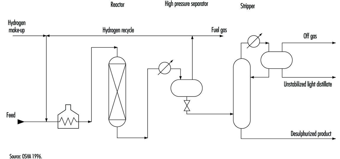
In hydrotreating, the hydrogen sulphide content of the feedstock must be strictly controlled to a minimum to reduce corrosion. Hydrogen chloride may form and condense as hydrochloric acid in the lower-temperature portions of the unit. Ammonium hydrosulphide may form in high-temperature, high-pressure units. In the event of a release, there is a potential for exposure to aromatic naphtha vapours which contain benzene, hydrogen sulphide or hydrogen gas, or to ammonia should a sour water leak or spill occur. Phenol may also be present if high-boiling-point feedstocks are processed.
Excessive contact time and/or temperature will create coking in the unit. Precautions need to be taken when unloading coked catalyst from the unit to prevent iron sulphide fires. The coked catalyst should be cooled to below 49 °C before removal, or dumped into nitrogen-inerted bins where it can be cooled before further handling. Special anti-foam additives may be used to prevent catalyst poisoning from silicone carryover in coker feedstock.
Other sweetening and treating processes
Treatment, drying and sweetening processes are used to remove impurities from blending stocks. (See figure 24.)
Figure 24. Sweetening & treating processes
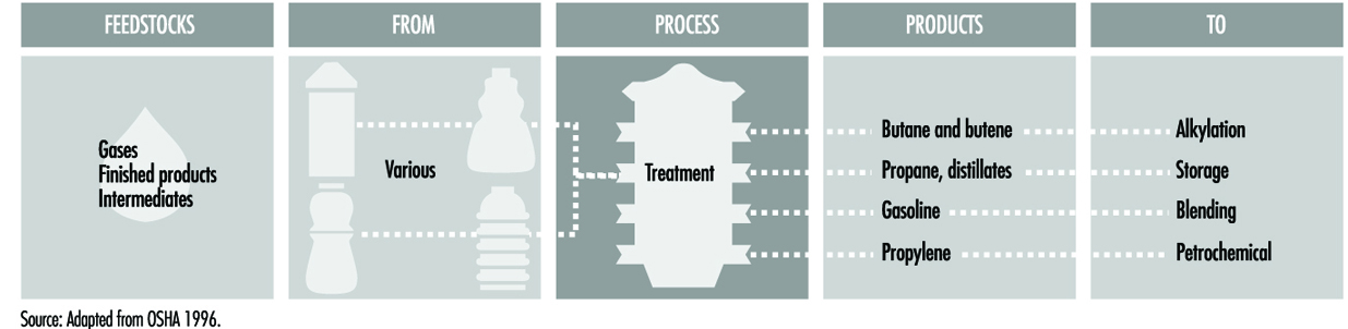
Sweetening processes use air or oxygen. If excess oxygen enters these processes, it is possible for a fire to occur in the settler due to the generation of static electricity. There is a potential for exposure to hydrogen sulphide, sulphur dioxide, caustic (sodium hydroxide), spent caustic, spent catalyst (Merox), catalyst dust and sweetening agents (sodium carbonate and sodium bicarbonate).
Amine (acid gas treatment) plants
Sour gas (fuel gas from processes such as catalytic cracking and hydrotreating, which contains hydrogen sulphide and carbon dioxide) must be treated before it can be used as refinery fuel. Amine plants remove acid contaminants from sour gas and hydrocarbon streams. In amine plants, gas and liquid hydrocarbon streams containing carbon dioxide and/or hydrogen sulphide are charged to a gas absorption tower or liquid contactor, where the acid contaminants are absorbed by counterflowing amine solutions—monoethanolamine (MEA), diethanolamine (DEA) or methyldiethanolamine (MDEA). The stripped gas or liquid is removed overhead, and the amine is sent to a regenerator. In the regenerator, the acidic components are stripped by heat and reboiling action, and disposed of, while the amine is recycled.
In order to minimize corrosion, proper operating practices should be established, and regenerator bottom and reboiler temperatures need to be controlled. Oxygen should be kept out of the system to prevent amine oxidation. There is potential for exposure to amine compounds (i.e., MEA, DEA, MDEA), hydrogen sulphide and carbon dioxide.
Sweetening and drying
Sweetening (mercaptan removal) treats sulphur compounds (hydrogen sulphide, thiophene and mercaptan) to improve colour, odour and oxidation stability, and reduces concentrations of carbon dioxide in gasoline. Some mercaptans are removed by having the product make contact with water-soluble chemicals (e.g., sulphuric acid) that react with the mercaptans. Caustic liquid (sodium hydroxide), amine compounds (diethanolamine) or fixed-bed catalyst sweetening may be used to convert mercaptans to less objectionable disulphides.
Product drying (water removal) is accomplished by water absorption, with or without adsorption agents. Some processes simultaneously dry and sweeten by adsorption on molecular sieves.
Sulphur recovery
Sulphur recovery removes hydrogen sulphide from sour gases and hydrocarbon streams. The Clause process converts hydrogen sulphide to elemental sulphur through the use of thermal and catalytic reactions. After burning hydrogen sulphide under controlled conditions, knockout pots remove water and hydrocarbons from feed-gas streams, which are then exposed to a catalyst to recover additional sulphur. The sulphur vapour from burning and conversion is condensed and recovered.
Tail gas treatment
Both oxidation and reduction are used to treat tail gas from sulphur recovery units, depending on the composition of the gas and on refinery economics. Oxidation processes burn tail gas to convert all sulphur compounds to sulphur dioxide, and reduction processes convert sulphur compounds to hydrogen sulphide.
Hydrogen sulphide scrubbing
Hydrogen sulphide scrubbing is a primary hydrocarbon feedstock treating process used to prevent catalyst poisoning. Depending on the feedstock and the nature of the contaminants, desulphurization methods will vary from ambient-temperature-activated charcoal absorption to high-temperature catalytic hydrogenation followed by zinc oxide treating.
Sat and unsat gas plants
Feedstocks from various refinery units are sent to gas treating plants, where butanes and butenes are removed for use as alkylation feedstock, heavier components are sent to gasoline blending, propane is recovered for LPG and propylene is removed for use in petrochemicals.
Sat gas plants separate components from refinery gases, including butanes for alkylation, pentanes for gasoline blending, LPGs for fuel and ethane for petrochemicals. There are two different sat gas processes: absorption-fractionation or straight fractionation. In absorption-fractionation, gases and liquids from various units are fed to an absorber/de-ethanizer where C2 and lighter fractions are separated by lean-oil absorption and removed for use as fuel gas or petrochemical feed. The remaining heavier fractions are stripped and sent to a debutanizer, and the lean oil is recycled back to the absorber/de-ethanizer. C3/C4 is separated from pentanes in the debutanizer, scrubbed to remove hydrogen sulphide, and fed to a splitter to separate propane and butane. The absorption stage is eliminated in fractionation plants. Sat gas processes depend on feedstock and product demand.
Corrosion occurs from the presence of hydrogen sulphide, carbon dioxide and other compounds as a result of prior treating. Streams containing ammonia should be dried before processing. Anti-fouling additives are used in absorption oil to protect heat exchangers. Corrosion inhibitors are used to control corrosion in overhead systems. The potential exists for exposure to hydrogen sulphide, carbon dioxide, sodium hydroxide, MEA, DEA and MDEA to be carried over from prior treating.
Unsat gas plants recover light hydrocarbons from wet gas streams from catalytic crackers and delayed coker overhead accumulators or fractionation receivers. In a typical process, wet gases are compressed and treated with amine to remove hydrogen sulphide either before or after entering a fractionating absorber, where they mix into a concurrent flow of debutanized gasoline. The light fractions are separated by heat in a reboiler, with the offgas sent to a sponge absorber and the bottoms sent to a debutanizer. A portion of the debutanized hydrocarbon is recycled, and the balance goes to a splitter for separation. Overhead gases go to a depropanizer for use as alkylation unit feedstock. (See figure 25.)
Figure 25. Unsat gas plant process
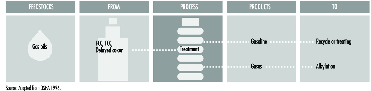
Corrosion can occur from moist hydrogen sulphide and cyanides in unsat gas plants which handle FCC feedstocks. Corrosion from hydrogen sulphide and deposits in the high-pressure sections of gas compressors from ammonium compounds is possible when feedstocks are from the delayed coker or the TCC. The potential exists for exposure to hydrogen sulphide and to amine compounds such as MEA, DEA and MDEA.
Gasoline, distillate fuel and lubricant base stock blending processes
Blending is the physical mixture of a number of different liquid hydrocarbon fractions to produce finished products with specific desired characteristics. Products can be blended in-line through a manifold system or batch blended in tanks and vessels. In-line blending of gasoline, distillates, jet fuel and lubricant base stocks is accomplished by injecting proportionate amounts of each component into the main stream where turbulence promotes thorough mixing.
- Gasolines are blends of reformates, alkylates, straight-run gasoline, thermal and catalytically cracked gasolines, coker gasoline, butane and appropriate additives.
- Fuel oil and diesel fuel are blends of distillates and cycle oils, and jet fuel may be straight-run distillate or blended with naphtha.
- Lubricating oils are blends of refined base stocks
- Asphalt is blended from various residual stocks depending on its intended use.
Additives are often mixed into gasoline and motor fuels during or after blending to provide specific properties not inherent in petroleum hydrocarbons. These additives include octane enhancers, anti-knock agents, anti-oxidants, gum inhibitors, foam inhibitors, rust inhibitors, carburettor (carbon) cleaners, detergents for injector cleaning, diesel odourizers, colour dyes, distillate anti-static, gasoline oxidizers such as methanol, ethanol and methyl tertiary butyl ether, metal deactivators and others.
Batch and in-line blending operations require strict controls to maintain desired product quality. Spills should be cleaned and leaks repaired to avoid slips and falls. Additives in drums and bags need to be handled properly to avoid strain and exposure. The potential for contacting hazardous additives, chemicals, benzene and other materials exists during blending, and appropriate engineering controls, personal protective equipment and proper hygiene are needed to minimize exposures.
Auxiliary Refinery Operations
Auxiliary operations supporting refinery processes include those which provide process heat and cooling; provide pressure relief; control air emissions; collect and treat waste water; provide utilities such as power, steam, air and plant gases; and pump, store, treat and cool process water.
Waste water treatment
Refinery waste water includes condensed steam, stripping water, spent caustic solutions, cooling tower and boiler blowdown, wash water, alkaline and acid waste neutralization water and other process-associated water. Waste water typically contains hydrocarbons, dissolved materials, suspended solids, phenols, ammonia, sulphides and other compounds. Waste water treatment is used for process water, runoff water and sewerage water prior to their discharge. These treatments may require permits, or there must be recycling.
The potential exists for fire should vapours from waste water containing hydrocarbons reach a source of ignition during the treatment process. The potential exists for exposure to the various chemicals and waste products during process sampling, inspection, maintenance and turnarounds.
Pretreatment
Pretreatment is the initial separation of hydrocarbons and solids from waste water. API separators, interceptor plates and settling ponds are used to remove suspended hydrocarbons, oily sludge and solids by gravity separation, skimming and filtration. Acidic waste water is neutralized with ammonia, lime or soda ash. Alkaline waste water is treated with sulphuric acid, hydrochloric acid, carbon dioxide-rich flue gas or sulphur. Some oil-in-water emulsions are first heated to help separate the oil and the water. Gravity separation depends on the different specific gravities of water and immiscible oil globules, which allows free oil to be skimmed off the surface of the waste water.
Sour water stripping
Water containing sulphides, called sour water, is produced in catalytic cracking and hydro-treating processes, and whenever steam is condensed in the presence of gases containing hydrogen sulphide.
Stripping is used on waste water containing sulphides and/or ammonia, and solvent extraction is used to remove phenols from waste water. Waste water which is to be recycled may require cooling to remove heat and/or oxidation by spraying or air stripping to remove any remaining phenols, nitrates and ammonia.
Secondary treatment
Following pretreatment, suspended solids are removed by sedimentation or air flotation. Waste water with low levels of solids is screened or filtered, and flocculation agents may be added to help separation. Materials with high adsorption characteristics are used in fixed-bed filters or added to the waste water to form a slurry which is removed by sedimentation or filtration. Secondary treatment processes biologically degrade and oxidize soluble organic matter by the use of activated sludge, unaerated or aerated lagoons, trickling filter methods or anaerobic treatments. Additional treatment methods are used to remove oils and chemicals from waste water.
Tertiary treatment
Tertiary treatments remove specific pollutants in order to meet regulatory discharge requirements. These treatments include chlorination, ozonation, ion exchange, reverse osmosis, activated carbon adsorption, and others. Compressed oxygen may be diffused into waste water streams to oxidize certain chemicals or to satisfy regulatory oxygen content requirements.
Cooling towers
Cooling towers remove heat from process water by evaporation and latent heat transfer between hot water and air. The two types of towers are counterflow and crossflow.
- In counterflow cooling, hot process water is pumped to the uppermost plenum and allowed to fall through the tower. Numerous slats, or spray nozzles, are located throughout the length of the tower to disperse the water flow and help in cooling. Simultaneously, air enters at the tower bottom, creating a concurrent flow of air against the water. Induced draft towers have the fans at the air outlet. Forced draft towers have the fans or blowers at the air inlet.
- Crossflow towers introduce airflow at right angles to the water flow throughout the structure.
Recirculated cooling water must be treated to remove impurities and any dissolved hydrocarbons. Impurities in cooling water can corrode and foul piping and heat exchangers, scale from dissolved salts can deposit on pipes, and wooden cooling towers can be damaged by micro-organisms.
Cooling tower water can be contaminated by process materials and by-products, including sulphur dioxide, hydrogen sulphide and carbon dioxide, with resultant exposures. There is potential for exposure to water treatment chemicals or to hydrogen sulphide when waste water is treated in conjunction with cooling towers. Because the water is saturated with oxygen from being cooled with air, the chances for corrosion are intensified. One means of corrosion prevention is the addition of a material to the cooling water which forms a protective film on pipes and other metal surfaces.
When cooling water is contaminated by hydrocarbons, flammable vapours can evaporate into the discharge air. If a source of ignition or lightning is present, fires may start. Fire hazards exist when there are relatively dry areas in induced-draft cooling towers of combustible construction. Loss of power to cooling tower fans or water pumps can create serious consequences in process operations.
Steam generation
Steam is produced through heater and boiler operations in central steam generation plants and at various process units, using heat from flue gas or other sources. Steam generation systems include:
- heaters (furnaces), with their burners and a combustion air system
- draft or pressure systems to remove flue gas from the furnace, soot blowers, and compressed air systems which seal openings to prevent flue gas from escaping
- boilers, consisting of a number of tubes which carry the water/steam mixture through the furnace providing for maximum heat transfer (these tubes run between steam distribution drums at the top of the boiler, and water collecting drums at the bottom of the boiler)
- steam drums to collect steam and direct it to the superheater before it enters the steam distribution system.
The most potentially hazardous operation in steam generation is heater start-up. A flammable mixture of gas and air can build up as a result of loss of flame at one or more burners during light-off. Specific start-up procedures are required for each different type of unit, including purging before light-off and emergency procedures in the event of misfire or loss of burner flame. If feedwater runs low and boilers are dry, the tubes will overheat and fail. Excess water will be carried over into the steam distribution system, causing damage to the turbines. Boilers should have continuous or intermittent blowdown systems to remove water from steam drums and to limit build-up of scale on turbine blades and superheater tubes. Care must be taken not to overheat the superheater during start-up and shut down. Alternate fuel sources should be provided in event of loss of fuel gas due to refinery unit shutdown or emergency.
Heater fuel
Any one or any combination of fuels, including refinery gas, natural gas, fuel oil and powdered coal may be used in heaters. Refinery off-gas is collected from process units and combined with natural gas and LPG in a fuel gas balance drum. The balance drum provides constant system pressure, fairly stable BTU (energy) content fuel and automatic separation of suspended liquids in gas vapours, and prevents carryover of large slugs of condensate into the distribution system.
Fuel oil is typically a mix of refinery crude oil and straight-run and cracked residues, blended with other products. The fuel oil system delivers fuel to process unit heaters and steam generators at required temperatures and pressures. The fuel oil is heated to pumping temperature, sucked through a coarse suction strainer, pumped to a temperature-control heater and then through a fine mesh strainer before being burned. Knockout pots, provided at process units, are used to remove liquids from fuel gas before burning.
In one example of process unit heat generation, carbon monoxide (CO) boilers recover heat in catalytic cracking units as carbon monoxide in flue gas is burned to complete combustion. In other processes, waste heat recovery units use heat from the flue gas to make steam.
Steam distribution
Steam typically is generated by heaters and boilers combined into one unit. Steam leaves the boilers at the highest pressure required by the process units or the electrical generator. The steam pressure is then reduced in turbines which drive process pumps and compressors. When refinery steam is also used to drive steam turbine generators to produce electricity, the steam must be produced at much higher pressure than required for process steam. The steam distribution system consists of valves, fittings, piping and connections which are suitable for the pressure of the steam transported. Most steam used in the refinery is condensed to water in heat exchangers and reused as boiler feedwater, or discharged to waste water treatment.
Steam feedwater
Feedwater supply is an important part of steam generation. There must always be as many pounds of water entering the steam generation system as there are pounds of steam leaving it. Water used in steam generation must be free of contaminants, including minerals and dissolved impurities, which can damage the system or affect the operation. Suspended materials such as silt, sewage and oil, which form scale and sludge, are coagulated or filtered out of the water. Dissolved gases, particularly carbon dioxide and oxygen which cause boiler corrosion, are removed by de-aeration and treatment. Dissolved minerals such as metallic salts, calcium and carbonates, which cause scale, corrosion and turbine blade deposits, are treated with lime or soda ash to precipitate them out of the water. Depending on its characteristics, raw boiler feedwater may be treated by clarification, sedimentation, filtration, ion exchange, de-aeration and internal treatment. Recirculated cooling water must also be treated to remove hydrocarbons and other contaminants.
Process heaters, heat exchangers and coolers
Process heaters and heat exchangers preheat feedstocks in distillation towers and in refinery processes to reaction temperatures. The major portion of heat provided to process units comes from fired heaters found on crude and reformer preheater units, coker heaters and large-column reboilers, which are fueled by refinery or natural gas, distillate and residual oils. Heaters are usually designed for specific process operations, and most are either cylindrical vertical or box-type designs. Heat exchangers use either steam or hot hydrocarbon, transferred from some other section of the process, for heat input.
Heat is also removed from some processes by air and water exchangers, fin fans, gas and liquid coolers and overhead condensers, or by transferring the heat to other systems. The basic mechanical vapour compression refrigeration system is designed to serve one or more process units, and includes an evaporator, compressor, condenser, controls and piping. Common coolants are water, alcohol/water mixture or various glycol solutions.
A means of providing adequate draft or steam purging is required to reduce the chance of explosions when lighting fires in heater furnaces. Specific start-up and emergency procedures are required for each type of unit. If fire impinges on fin fans, failure could occur due to overheating. If flammable product escapes from a heat exchanger or cooler due to a leak, a fire could occur.
Care must be taken to assure that all pressure is removed from heater tubes before removing any header or fitting plugs. Consideration should be given to providing for pressure relief in heat exchanger piping systems in the event they are blocked off while full of liquid. If controls fail, variations of temperature and pressure could occur on either side of the heat exchanger. If heat exchanger tubes fail and process pressure is greater than heater pressure, product could enter the heater with downstream consequences. If the pressure is less, the heater stream could enter into the process fluid stream. If loss of circulation occurs in liquid or gas coolers, increased product temperature could affect downstream operations, requiring pressure relief.
Depending on the fuel, process operation and unit design, there is a potential for exposure to hydrogen sulphide, carbon monoxide, hydrocarbons, steam boiler feedwater sludge and water treatment chemicals. Skin contact with boiler blowdown which may contain phenolic compounds should be avoided. Exposure to radiant heat, superheated steam and hot hydrocarbons is possible.
Pressure relief and flare systems
Engineering controls which are incorporated into processes include reducing flammable vapour concentrations by ventilation, dilution and inerting. Pressurization is used to maintain control rooms above atmospheric pressure in order to reduce the possibility of vapours entering. Pressure relief systems are provided to control vapours and liquids which are released by pressure-relieving devices and blowdowns. Pressure relief is an automatic, planned release when operating pressure reaches a predetermined level. Blowdown usually refers to the intentional release of material, such as blowdowns from process unit start-ups, furnace blowdowns, shutdowns and emergencies. Vapour depressuring is the rapid removal of vapours from pressure vessels in case of emergency. This may be accomplished by the use of a rupture disc, usually set at a higher pressure than the relief valve.
Safety relief valves
Safety relief valves, used to control air, steam, gas and hydrocarbon vapour and liquid pressures, open in proportion to the increase in pressure over the normal operating pressure. Safety valves, designed primarily to release high volumes of steam, usually pop open to full capacity. The overpressure needed to open liquid relief valves, where large-volume discharge is not required, increases as the valve lifts due to increased spring resistance. Pilot-operated safety release valves, with up to six times the capacity of normal relief valves, are used where tighter sealing and larger-volume discharges are required. Non-volatile liquids are usually pumped to oil/water separation and recovery systems, and volatile liquids are sent to units operating at a lower pressure.
Flares
A typical closed pressure-release and flare system includes relief valves and lines from process units for collection of discharges, knockout drums to separate vapours and liquids, seals and/or purge gas for flashback protection and a flare and igniter system, which combusts vapours if discharge direct to the atmosphere is not permitted. Steam may be injected into the flare tip to reduce visible smoke.
Liquids should not be allowed to discharge to a vapour disposal system. Flare knockout drums and flares need to be large enough to handle emergency blowdowns, and drums require relief in event of overpressure. Provide pressure relief valves where the potential exists for overpressure in refinery processes, such as due to the following causes:
- loss of cooling water, possibly resulting in a greatly increased pressure drop in condensers, in turn increasing the pressure in the process unit
- rapid vaporization and pressure increase from injection of a lower-boiling-point liquid, including water, into a process vessel operating at higher temperatures
- expansion of vapour and resultant overpressure due to overheated process steam, malfunctioning heaters or fire
- failure of automatic controls, closed outlets, heat exchanger failure, etc.
- internal explosion, chemical reaction, thermal expansion, accumulated gases, etc.
- loss of reflux, causing a pressure rise in distillation towers.
Because the quantity of reflux affects the volume of vapours leaving the distillation tower, loss of volume causes a pressure drop in condensers and a pressure rise in distillation towers.
Maintenance is important because valves are required to function properly. Common valve operating problems include:
- failure to open at set pressure due to plugging of the valve inlet or outlet or by corrosion, preventing proper operation of the disc holder and guides
- failure to reseat after popping open due to fouling, corrosion or deposits on the seat or moving parts, or by solids in the gas stream cutting the valve disc
- chattering and premature opening, due to operating pressure being too close to the valve set point.
Utilities
Water. Depending on location and community resources, refineries may draw upon public water supplies for drinking and process water or may have to pump and treat their own potable water. Treatment may include a wide range of requirements, from desalting to filtration, chlorination and testing.
Sewage. Also, depending on availability of community or private offsite treatment plants, refineries may have to provide for the permitting, collection, treatment and discharge of their sanitary waste.
Electric power. Refineries either receive electricity from outside sources or produce their own, using electric generators driven by steam turbines or gas engines. Areas are classified with regard to the type of electrical protection required to prevent a spark from igniting vapours or contain an explosion within electrical equipment. Electrical substations, which are normally located in non-classified areas, away from sources of flammable hydrocarbon vapour or cooling tower water spray, contain transformers, circuit breakers and feed circuit switches. Substations feed power to distribution stations within the process unit areas. Distribution stations can be located in classified areas, provided that electrical classification requirements are met. Distribution stations typically use a liquid-filled transformer provided with an oil-filled or air-break disconnect device.
Normal electrical safety precautions, including dry footing, “high voltage” warning signs and guarding should be implemented to protect against electrocution. Employees should be familiar with refinery electrical safe work procedures. Lockout/tagout and other appropriate safe work practices should be implemented to prevent energizing while work is being performed on high-voltage electrical equipment. Hazardous exposures may occur when working around transformers and switches which contain a dielectric fluid requiring special handling precautions. These subjects are discussed more fully elsewhere in this Encyclopaedia.
Turbine, gas and air compressor operations
Air and gas compressors
Refinery exhaust ventilation and air supply systems are designed to capture or dilute gases, fumes, dusts and vapours which may contaminate working spaces or the outside atmosphere. Captured contaminants are reclaimed if feasible, or directed to disposal systems after being cleaned or burned. Air supply systems include compressors, coolers, air receivers, air dryers, controls and distribution piping. Blowers are also used to provide air to certain processes. Plant air is provided for the operation of air-powered tools, catalyst regeneration, process heaters, steam-air decoking, sour water oxidation, gasoline sweetening, asphalt blowing and other uses. Instrument air is provided for use in pneumatic instruments and controls, air motors and purge connections. Plant gas, such as nitrogen, is provided for inerting vessels and other uses. Both reciprocating and centrifugal compressors are used for gas and compressed air.
Air compressors should be located so that the suction does not take in flammable vapours or corrosive gases. There is a potential for fire should a leak occur in gas compressors. Knockout drums are needed to prevent liquid surges from entering gas compressors. If gases are contaminated with solid materials, strainers are needed. Failure of automatic compressor controls will affect processes. If maximum pressure could potentially be greater than compressor or process equipment design pressure, pressure relief should be provided. Guarding is needed for exposed moving parts on compressors. Compressor buildings should be properly electrically classified, and provisions made for proper ventilation.
Where plant air is used as back-up to instrument air, interconnections must be upstream of the instrument air drying system to prevent contamination of instruments with moisture. Alternate sources of instrument air supply, such as use of nitrogen, may be needed in the event of power outages or compressor failure. Apply appropriate safeguards so that gas, plant air and instrument air are not used as the source for breathing or for pressuring potable water systems.
Turbines
Turbines are usually gas or steam powered and are used to drive pumps, compressors, blowers and other refinery process equipment. Steam enters turbines at high temperatures and pressures, expanding across and driving rotating blades while directed by fixed blades.
Steam turbines used for exhaust operating under vacuum need a safety relief valve on the discharge side for protection and to maintain steam in event of vacuum failure. Where maximum operating pressure could be greater than design pressure, steam turbines need relief devices. Consideration should be given to providing governors and overspeed-control devices on turbines.
Pumps, Piping and Valves
Centrifugal and positive displacement (reciprocating) pumps are used to move hydrocarbons, process water, fire water and waste water throughout the refinery. Pumps are driven by electric motors, steam turbines or internal combustion engines.
Process and utility piping systems distribute hydrocarbons, steam, water and other products throughout the facility. They are sized and constructed of materials dependent on the type of service, pressure, temperature and nature of the products. There are vent, drain and sample connections on piping, as well as provisions for blanking. Different types of valves, including gate valves, bypass valves, globe and ball valves, plug valves, block and bleed valves and check valves are used, depending on their operating purpose. These valves can be operated manually or automatically.
Valves and instrumentation which require servicing or other work should be accessible at grade level or from an operating platform. Remote-controlled valves, fire valves and isolation valves may be used to limit the loss of product at pump suction lines in the event of leakage or fire. Operating vent and drain connections may be provided with double block valves, or a block valve and plug or blind flange for protection against releases. Depending on the product and service, backflow prevention from the discharge line may be needed. Provisions may be made for pipeline expansion, movement and temperature changes to avoid rupture. Pumps operated with reduced or no flow can overheat and rupture. The failure of automatic pump controls could cause a deviation in process pressure and temperature. Pressure relief in the discharge piping should be provided where pumps can be overpressured.
Tank storage
Atmospheric storage tanks and pressure storage tanks are used throughout the refinery for storage of crudes, intermediate hydrocarbons (those used for processing) and finished products, both liquids and gases. Tanks are also provided for fire water, process and treatment water, acids, air and hydrogen, additives and other chemicals. The type, construction, capacity and location of tanks depends on their use and the nature, vapour pressure, flashpoints and pour points of the materials stored. Many types of tanks are used in refineries, the simplest being above-ground, cone-roof tanks for storage of combustible (non-volatile) liquids such as diesel fuels, fuel oils and lubricating oils. Open-top and covered (internal) floating-roof tanks, which store flammable (volatile) liquids such as gasoline and crude oil, restrict the amount of space between the top of the product and the tank roof in order to maintain a vapour-rich atmosphere to preclude ignition.
The potential for fire exists if hydrocarbon storage tanks are overfilled or develop leaks which allow liquid and vapours to escape and reach sources of ignition. Refineries should establish manual gauging and product receipt procedures to control overfills or provide automatic overflow control and signaling systems on tanks. Tanks may be equipped with fixed or semi-fixed foam-water fire protection systems. Remote-controlled valves, isolation valves and fire valves may be provided at tanks for pump-out or closure in the event of a fire inside the tank or in the tank dike or storage area. Tank venting, cleaning and confined-space entry programmes are used to control work inside tanks, and hot work permit systems are used to control sources of ignition in and around storage tanks.
Handling, shipping and transportation
Loading gases and liquid hydrocarbons into pipelines, tank cars, tank trucks and marine vessels and barges for transport to terminals and consumers is the final refinery operation. Product characteristics, distribution needs, shipping requirements, fire prevention, and environmental protection and operating criteria are important when designing marine docks, loading racks and pipeline manifolds. Operating procedures need to be established and agreed to by the shipper and receiver, and communications maintained during product transfer. Tank trucks and rail tank cars may be either top or bottom loaded. Loading and unloading liquefied petroleum gas (LPG) requires special considerations over and above those for liquid hydrocarbons. Where required, vapour recovery systems should be provided at loading racks and marine docks.
Safe work practices and appropriate personal protective equipment may be needed when loading or unloading, cleaning up spills or leaks, or when gauging, inspecting, sampling or performing maintenance activities on loading facilities or vapour recovery systems. Delivery should be stopped or diverted in the event of an emergency such as a tank truck or tank car compartment overfill.
A number of different hazardous and toxic chemicals are used in refineries, varying from small amounts of test reagents used in laboratories to large quantities of sulphuric acid and hydrofluoric acids used in alkaline processing. These chemicals need to be received, stored and handled properly. Chemical manufacturers provide material safety information which can be used by refineries to develop safety procedures, engineering controls, personal protection requirements and emergency response procedures for handling chemicals.
The nature of the hazard at loading and unloading facilities depends upon the products being loaded and the products previously transported in the tank car, tank truck or marine vessel. Bonding equalizes the electrical charge between the loading rack and the tank truck or tank car. Grounding prevents the flow of stray currents at truck and rail loading facilities. Insulating flanges are used on marine dock piping connections to prevent static electricity build-up and discharges. Flame arrestors are installed in loading rack and marine vapour recovery lines to prevent flashback. Where switch loading is permitted, safe procedures should be established and followed.
Automatic or manual shutoff systems at supply headers should be provided at top- and bottom-loading racks and marine docks in the event of leaks or overfills. Anti-fall protection, such as hand rails, may be needed for docks and top-loading racks. Drainage and recovery systems may be provided at loading racks for storm drainage, at docks and to handle spills and leaks. Precautions are needed at LPG-loading facilities so as not to overload or overpressurize tank cars and trucks.
Refinery Support Activities and Facilities
A number of different facilities, activities and programmes, each of which has its own specific safety and health requirements, are needed to support refinery processes depending on the refinery’s location and available resources.
Administrative activities
A wide variety of administrative support activities, depending on the refining company’s philosophy and the availability of community services, are required to assure continued operation of a refinery. The function which controls oil movements into, within and out from the refinery is unique to refineries. The administrative functions can be broken down as follows. The day-to-day operation of the process units is the operations function. Another function is responsible for assuring that arrangements have been made for a continuous supply of crude oil. Other functional activities include medical services (both emergency and continuing health care), food service, engineering services, janitorial services and routine administrative and management functions common to most industries, such as accounting, purchasing, human relations and so on. The refinery training function is responsible for supervisor and employee skills and crafts training including initial, refresher and remedial training, and for employee and contractor orientation and training in emergency response and safe work practices and procedures.
Construction and maintenance
The continued safe operation of refineries depends upon the establishment and implementation of programmes and procedures for regular maintenance and preventive maintenance, and assuring replacement when necessary. Turnarounds, wherein the entire refinery or entire process units will be shut down for total equipment overall and replacement at one time, is a type of preventive maintenance programme unique to the process industry. Mechanical integrity activities, such as inspection, repair, testing and certification of valves and relief devices, which are part of the process safety management programme, are important to the continued safe operation of a refinery, as are maintenance work orders for the continued effectiveness of the refinery “management of change” programme. Work permit programmes control hot work and safe work, such as isolation and lockout, and entry into confined spaces. Maintenance and instrumentation shops have purposes which include:
- delicate and precise work to test, maintain and calibrate refinery process controls, instruments and computers
- welding
- equipment repair and overhaul
- vehicle maintenance
- carpentry and so on.
Construction and maintenance safety and health relies on some of the following programmes.
Isolation
The safe maintenance, repair and replacement of equipment within process units often requires the isolation of tanks, vessels and lines in order to preclude the possibility of flammable liquids or vapours entering an area where hot work is being performed. Isolation is normally attained by disconnecting and closing off all of the piping leading to or from a vessel; blinding or blanking the pipe at a connection near the tank or vessel; or closing a double set of block valves on the piping, if provided, and opening a bleeder valve between the two closed valves.
Lockout/tagout
Lockout and tagout programmes prevent the inadvertent activation of electrical, mechanical, hydraulic or pneumatically energized equipment during repair or maintenance. All electrically powered equipment should have its circuit breaker or main switch locked or tagged out and tested to assure non-operability, prior to starting work. Mechanical hydraulic and pneumatic equipment should be de-energized and have its power source locked or tagged out prior to starting work. Valve closing lines which are being worked on, or which are isolated, should also be locked out or tagged to prevent unauthorized opening.
Metallurgy
Metallurgy is used to assure the continued strength and integrity of lines, vessels, tanks and reactors which are subject to corrosion from the acids, corrosives, sour water, and gases and other chemicals created by and used in processing crude oil. Non-destructive testing methods are employed throughout the refinery to detect excessive corrosion and wear before failure occurs. Proper safety precautions are required to prevent excessive exposures to workers who are handling or are exposed to radioactive testing equipment, dyes and chemicals.
Warehouses
Warehouses store not only the parts, materials and equipment needed for continued refinery operations, but also store packaged chemicals and additives that are used in maintenance, processing and blending. Warehouses may also maintain supplies of required personal protective clothing and equipment including hard hats, gloves, aprons, eye and face protection, respiratory protection, safety and impervious footwear, flame-resistant clothing and acid-protective clothing. Proper storage and separation of flammable and combustible liquids and hazardous chemicals is needed to prevent spills, fires and mixing of incompatible products.
Laboratories
Laboratories are responsible for determining the values and consistency of the crude oils prior to processing, as well as performing the testing required for finished product quality control. Laboratory personnel should be trained to recognize the hazards inherent in the handling and mixing of toxic chemicals and flammable liquids, and provide protection for themselves and others.
Safety and environmental and occupational hygiene
Other important refinery support activities are safety, fire prevention and protection, environmental protection and industrial hygiene. These may be provided as separate functions or integrated into the refinery operations. Safety, emergency preparedness and response, and fire prevention and protection activities are often the responsibility of the same function within a refinery.
The safety function participates in process safety management programmes as part of the design review, pre-construction and construction review and pre-start-up review teams. Safety often assists in the contractor qualification process, reviews contractor activities and investigates incidents involving employees and contractors. Safety personnel may be responsible for overseeing permit-required activities such as confined space entry and hot work, and for checking the availability and readiness of portable fire extinguishers, decontamination facilities, safety showers, eye wash stations, fixed detection devices and alarms, and emergency self-contained breathing apparatus placed at strategic locations in event of a toxic gas release.
Safety programmes. The refinery safety function usually has responsibility for the development and administration of various safety and incident prevention programmes, including, but not limited to, the following:
- design construction and pre-start-up safety reviews
- accident, incident and near miss investigation and reporting
- emergency preparedness plans and response programmes
- contractor safety programme
- safe work practices and procedures
- lockout/tagout
- confined and inert space entry
- scaffolding
- electrical safety, equipment grounding and fault protection programme
- machine guarding
- safety signs and notices
- hot work, safe work and entry permit systems.
Fire brigades. Refinery fire brigades and emergency responders may be full-time brigade members; designated refinery employees, such as operators and maintenance personnel who are trained and assigned to respond in addition to their regular duties; or a combination of both. Besides fires, brigades traditionally respond to other refinery incidents such as acid or gas releases, rescue from vessels or tanks, spills and so on. The fire protection function may be responsible for the inspection and testing of fire detectors and signals, and fixed and portable fire protection systems and equipment, including fire trucks, fire pumps, fire water lines, hydrants, hoses and nozzles.
Refinery firefighting differs from normal firefighting because rather than extinguishment, it is often preferable to allow certain fires to continue to burn. In addition, each type of hydrocarbon liquid, gas and vapour has unique fire chemistry characteristics which must be thoroughly understood in order to best control their fires. For example, extinguishment of a hydrocarbon vapour fire without first stopping the vapour release, would only create a continued vapour gas cloud with the probability of re-ignition and explosion. Fires in tanks containing crude oil and heavy residuals need to be handled with specific firefighting techniques to avoid the possibility of an explosion or tank boil-over.
Hydrocarbon fires are often extinguished by stopping the flow of product and allowing the fire to burn out while applying cooling water to protect adjacent equipment, tanks and vessels from heat exposures. Many fixed fire protection systems are designed with this specific purpose. Fighting fires in process units under pressure requires special consideration and training, particularly when catalysts such as hydrofluoric acid are involved. Special firefighting chemicals, such as dry powder and foam-water solutions, may be used to extinguish hydrocarbon fires and control vapour emissions.
Emergency preparedness. Refineries need to develop and implement emergency response plans for a number of different potential situations, including explosions, fires, releases and rescues. The emergency plans should include the use of outside assistance, including contractors, governmental and mutual aid as well as availability of special supplies and equipment, such as firefighting foam and spill containment and adsorption materials.
Gas and vapour testing
Gas, particulate and vapour monitoring, sampling and testing in refineries is conducted to assure that work can be performed safely and processes can be operated without toxic or hazardous exposures, explosions or fires. Atmospheric testing is conducted using a variety of instruments and techniques to measure oxygen content, hydrocarbon vapours and gases, and to determine hazardous and toxic exposure levels. Instruments must be properly calibrated and adjusted prior to use, by qualified persons, to assure dependable and accurate measurements. Depending on the work location, potential hazards and type of work being performed, testing, sampling and monitoring may be conducted prior to the start of work, or at specified intervals during work, or continuously throughout the course of work.
When establishing refinery procedures for sampling and testing flammable, inert and toxic atmospheres, the use of personal protective equipment, including appropriate respiratory protection, should be considered. It should be noted that canister-type respirators are unsuitable for oxygen-deficient atmospheres. Testing requirements should depend upon the degree of hazard which would be present in the event of instrument failure.
Testing of the following substances may be performed using portable equipment or fixed instrumentation:
Oxygen. Combustible gas meters work by burning a minute sample of the atmosphere being tested. In order to obtain an accurate combustible gas reading, a minimum of 10% and a maximum of 25% oxygen must be present in the atmosphere. The amount of oxygen present in the atmosphere is determined by using an oxygen meter prior to, or simultaneously with, using the combustible gas meter. Testing for oxygen is essential when working in confined or enclosed spaces, as entry without respiratory protection (provided that there are no toxic exposures) requires normal breathing-air oxygen concentrations of approximately 21%. Oxygen meters are also used to measure the amount of oxygen present in inerted spaces, to assure that there is not enough present to support combustion during hot work or other operations.
Hydrocarbon vapours and gases. “Hot work” is work which creates a source of ignition, such as welding, cutting, grinding, blast cleaning, operating an internal combustion engine and so on, in an area where the potential for exposure to flammable vapours and gases exists. In order to conduct hot work safely, instruments known as combustible gas meters are used to test the atmosphere for hydrocarbon vapours. Hydrocarbon vapours or gases will burn only when mixed with air (oxygen) in certain proportions and ignited. If there is not enough vapour in the air, the mixture is said to be “too lean to burn”, and if there is too much vapour (too little oxygen), the mixture is “too rich to burn”. The limiting proportions are called the “upper and lower flammable limits” and are expressed as a percentage of volume of vapour in air. Each hydrocarbon molecule or mixture has different flammability limits, typically ranging from about 1 to 10% vapour in air. Gasoline vapour, for example, has a lower flammable limit of 1.4% and an upper flammable limit of 7.6 per cent.
Toxic atmospheres. Special instruments are used to measure the levels of toxic and hazardous gases, vapours and particulates which may be present in the atmosphere where people are working. These measurements are used to determine the level and type of protection needed, which may vary from complete ventilation and replacement of the atmosphere to the use of respiratory and personal protective equipment by people working in the area. Examples of hazardous and toxic exposures which may be found in refineries include asbestos, benzene, hydrogen sulphide, chlorine, carbon dioxide, sulphuric and hydrofluoric acids, amines, phenol and others.
Health and safety programmes
The basis for refinery industrial hygiene is an administrative and engineering controls programme covering facility exposures to toxic and hazardous chemicals, laboratory safety and hygiene, ergonomics and medical surveillance.
Regulatory agencies and companies establish exposure limitations for various toxic and hazardous chemicals. The occupational hygiene function conducts monitoring and sampling to measure employee exposure to hazardous and toxic chemicals and substances. Industrial hygienists may develop or recommend engineering controls, preventive work practices, product substitution, personal protective clothing and equipment or alternate measures of protection or reducing exposure.
Medical programmes. Refineries typically require preplacement and periodic medical examinations to determine the employee’s ability to initially and subsequently perform the work, and assure that the continued work requirements and exposures will not endanger the employee’s health or safety.
Personal protection. Personal protection programmes should cover typical refinery exposures, such as noise, asbestos, insulation, hazardous waste, hydrogen sulphide, benzene and process chemicals including caustics, hydrogen fluoride, sulphuric acid and so on. Industrial hygiene may designate the appropriate personal protective equipment to be used for various exposures, including negative pressure and air-supplied respirators and hearing, eye and skin protection.
Product safety. Product safety awareness covers knowing about the hazards of chemicals and materials to which the potential for exposure exists in the workplace, and what actions to take in the event exposure by ingestion, inhalation or skin contact occurs. Toxicological studies of crude oil, refinery streams, process chemicals, finished products and proposed new products are conducted to determine the potential effects of exposure on both employees and consumers. The data are used to develop health information concerning permissible limits of exposure or acceptable amounts of hazardous materials in products. This information is typically distributed by material safety data sheets (MSDSs) or similar documents, and employees are trained or educated in the hazards of the materials in the workplace.
Environmental Protection
Environmental protection is an important consideration in refinery operations because of regulatory compliance requirements and a need for conservation as oil prices and costs escalate. Oil refineries produce a wide range of air and water emissions that can be hazardous to the environment. Some of these are contaminants in the original crude oil, while others are a result of refinery processes and operations. Air emissions include hydrogen sulphide, sulphur dioxide, nitrogen oxides and carbon monoxide (see table 2). Waste water typically contains hydrocarbons, dissolved materials, suspended solids, phenols, ammonia, sulphides, acids, alkalis and other contaminants. There is also the risk of accidental spills and leaks of a wide range of flammable and/or toxic chemicals.
Controls established to contain liquid and vapour releases and reduce operating costs include the following:
- Energy conservation. Controls include steam leak control and condensate recovery programmes to conserve energy and increase efficiency.
- Water pollution. Controls include waste water treatment in API separators and subsequent treatment facilities, storm water collection, retainment and treatment and spill prevention containment and control programmes.
- Air pollution. Since refineries operate continuously, leak detection, particularly at valves and pipe connections, is important. Controls include reducing hydrocarbon vapour emissions and releases to the atmosphere, refinery valve and fitting tightness programmes, floating roof tank seals and vapour containment programmes, and vapour recovery for loading and unloading facilities and for venting tanks and vessels.
- Ground pollution. Preventing oil spillage from polluting soil and contaminating ground water is accomplished by the use of dikes and the providing of drainage to specified, protected containment areas. Contamination from spillage inside dike areas may be prevented by the use of secondary containment measures, such as impervious plastic or clay dike liners.
- Spill response. Refineries should develop and implement programmes to respond to spills of crude oil, chemicals and finished products, on both land and water. These programmes may rely on trained employees or outside agencies and contractors to respond to the emergency. The type, amount needed and availability of spill clean-up and restoration supplies and equipment, either on site or on call, should be included in the preparedness plan.
Pharmaceutical Industry
Definitions
These terms are used frequently in the pharmaceutical industry:
Biologics are bacterial and viral vaccines, antigens, antitoxins and analogous products, serums, plasmas and other blood derivatives for therapeutically protecting or treating humans and animals.
Bulks are active drug substances used to manufacture dosage- form products, process medicated animal feeds or compound prescription medications.
Diagnostic agents assist the diagnosis of diseases and disorders in humans and animals. Diagnostic agents may be inorganic chemicals for examining the gastrointestinal tract, organic chemicals for visualizing the circulatory system and liver and radioactive compounds for measuring the function of organ system.
Drugs are substances with active pharmacological properties in humans and animals. Drugs are compounded with other materials, such as pharmaceutical necessities, to produce a medicinal product.
Ethical pharmaceuticals are biological and chemicals agents for preventing, diagnosing or treating disease and disorders in humans or animals. These products are dispensed by prescription or approval of a medical, pharmacy or veterinary professional.
Excipients are inert ingredients which are combined with drug substances to create a dosage form product. Excipients may affect the rate of absorption, dissolution, metabolism and distribution in humans or animals.
Over-the-counter pharmaceuticals are drug products sold in a retail store or pharmacy which do not require a prescription or the approval of a medical, pharmacy or veterinary professional.
Pharmacy is the art and science of preparing and dispensing drugs for preventing, diagnosing or treating diseases or disorders in humans and animals.
Pharmacokinetics is the study of metabolic processes relating to the absorption, distribution, biotransformation, and elimination of a drug in humans or animals.
Pharmacodynamics is the study of drug action relating to its chemical structure, site of action, and the biochemical and physiological consequences in humans and animals.
The pharmaceutical industry is an important component of health care systems throughout the world; it is comprised of many public and private organizations that discover, develop, manufacture and market medicines for human and animal health (Gennaro 1990). The pharmaceutical industry is based primarily upon the scientific research and development (R&D) of medicines that prevent or treat diseases and disorders. Drug substances exhibit a wide range of pharmacological activity and toxicological properties (Hardman, Gilman and Limbird 1996; Reynolds 1989). Modern scientific and technological advances are accelerating the discovery and development of innovative pharmaceuticals with improved therapeutic activity and reduced side effects. Molecular biologists, medicinal chemists and pharmacists are improving the benefits of drugs through increased potency and specificity. These advances create new concerns for protecting the health and safety of workers within the pharmaceutical industry (Agius 1989; Naumann et al. 1996; Sargent and Kirk 1988; Teichman, Fallon and Brandt-Rauf 1988).
Many dynamic scientific, social and economic factors affect the pharmaceutical industry. Some pharmaceutical companies operate in both national and multinational markets. Therefore, their activities are subject to legislation, regulation and policies relating to drug development and approval, manufacturing and quality control, marketing and sales (Spilker 1994). Academic, government and industry scientists, practising physicians and pharmacists, as well as the public, influence the pharmaceutical industry. Health care providers (e.g., physicians, dentists, nurses, pharmacists and veterinarians) in hospitals, clinics, pharmacies and private practice may prescribe drugs or recommend how they should be dispensed. Government regulations and health care policies on pharmaceuticals are influenced by the public, advocacy groups and private interests. These complex factors interact to influence the discovery and development, manufacturing, marketing and sales of drugs.
The pharmaceutical industry is largely driven by scientific discovery and development, in conjunction with toxicological and clinical experience (see figure 1). Major differences exist between large organizations which engage in a broad range of drug discovery and development, manufacturing and quality control, marketing and sales and smaller organizations which focus on a specific aspect. Most multinational pharmaceutical companies are involved in all these activities; however, they may specialize in one aspect based upon local market factors. Academic, public and private organizations perform scientific research to discover and develop new drugs. The biotechnology industry is becoming a major contributor to innovative pharmaceutical research (Swarbick and Boylan 1996). Often, collaborative agreements between research organizations and large pharmaceutical companies are formed to explore the potential of new drug substances.
Figure 1. Drug development in the pharmaceutical industry
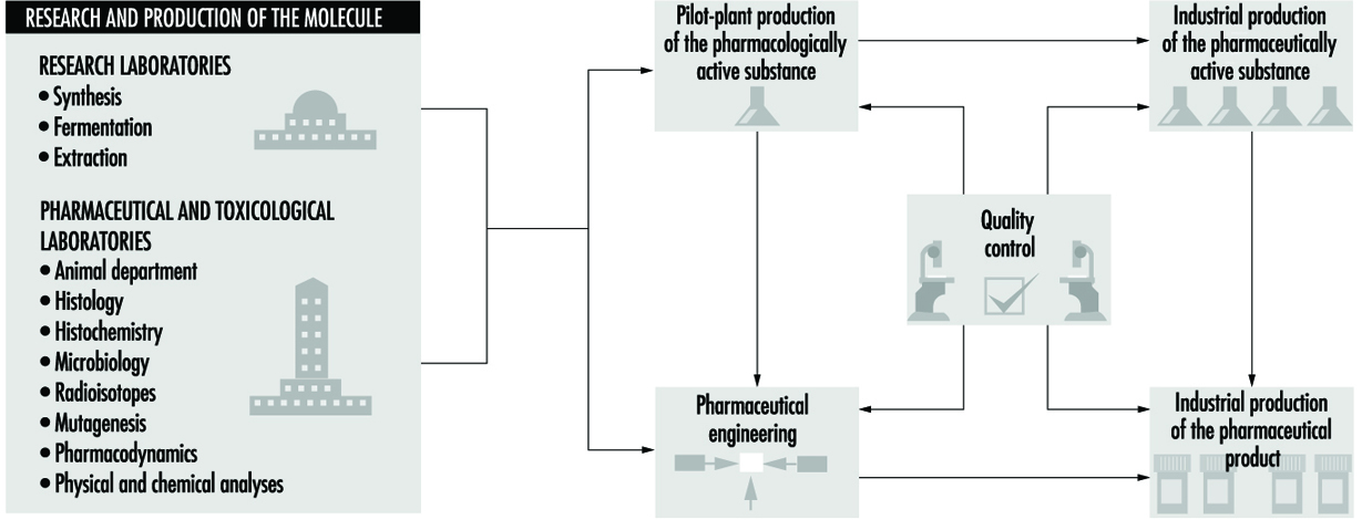
Many countries have specific legal protections for proprietary drugs and manufacturing processes, known as intellectual property rights. In instances when legal protections are limited or do not exist, some companies specialize in manufacturing and marketing generic drugs (Medical Economics Co. 1995). The pharmaceutical industry requires large amounts of capital investment due to the high expenses associated with R&D, regulatory approval, manufacturing, quality assurance and control, marketing and sales (Spilker 1994). Many countries have extensive government regulations affecting the development and approval of drugs for commercial sale. These countries have strict requirements for good manufacturing practices to ensure the integrity of drug manufacturing operations and the quality, safety and efficacy of pharmaceutical products (Gennaro 1990).
International and domestic trade, as well as tax and finance policies and practices, affect how the pharmaceutical industry operates within a country (Swarbick and Boylan 1996). Significant differences exist between developed and developing countries, regarding their needs for pharmaceutical substances. In developing countries, where malnutrition and infectious diseases are prevalent, nutritional supplements, vitamins and anti-infective drugs are most needed. In developed countries, where the diseases associated with ageing and specific ailments are primary health concerns, cardiovascular, central nervous system, gastrointestinal, anti-infective, diabetes and chemotherapy drugs are in the greatest demand.
Human and animal health drugs share similar R&D activities and manufacturing processes; however, they have unique therapeutic benefits and mechanisms for their approval, distribution, marketing and sales (Swarbick and Boylan 1996). Veterinarians administer drugs to control infectious diseases and parasitic organisms in agricultural and companion animals. Vaccines and anti-infective and antiparasitic drugs are commonly used for this purpose. Nutritional supplements, antibiotics and hormones are widely employed by modern agriculture to promote the growth and health of farm animals. The R&D of pharmaceuticals for human and animal health are often allied, due to concurrent needs to control infectious agents and disease.
Hazardous Industrial Chemicals and Drug-related Substances
Many different biological and chemical agents are discovered, developed and used in the pharmaceutical industry (Hardman, Gilman and Limbird 1996; Reynolds 1989). Some manufacturing processes in the pharmaceutical, biochemical and synthetic organic chemical industries are similar; however, the greater diversity, smaller scale and specific applications in the pharmaceutical industry are unique. Since the primary purpose is to produce medicinal substances with pharmacological activity, many agents in pharmaceutical R&D and manufacturing are hazardous to workers. Proper control measures must be implemented to protect workers from industrial chemicals and drug substances during many R&D, manufacturing and quality control operations (ILO 1983; Naumann et al. 1996; Teichman, Fallon and Brandt-Rauf 1988).
The pharmaceutical industry uses biological agents (e.g., bacteria and viruses) in many special applications, such as vaccine production, fermentation processes, derivation of blood-based products and biotechnology. Biological agents are not addressed by this profile due to their unique pharmaceutical applications, but other references are readily available (Swarbick and Boylan 1996). Chemical agents may be categorized as industrial chemicals and drug-related substances (Gennaro 1990). These may be raw materials, intermediates or finished products. Special situations arise when industrial chemicals or drug substances are employed in laboratory R&D, quality assurance and control assays, engineering and maintenance, or when they are created as by-products or wastes.
Industrial chemicals
Industrial chemicals are used in researching and developing active drug substances and manufacturing bulk substances and finished pharmaceutical products. Organic and inorganic chemicals are raw materials, serving as reactants, reagents, catalysts and solvents. The use of industrial chemicals is determined by the specific manufacturing process and operations. Many of these materials may be hazardous to workers. Since worker exposures to industrial chemicals may be hazardous, occupational exposure limits, such as threshold limit values (TLVs) have been established by government, technical and professional organizations (ACGIH 1995).
Drug-related substances
Pharmacologically active substances may be categorized as natural products and synthetic drugs. Natural products are derived from plant and animal sources, while synthetic drugs are produced by microbiological and chemical technologies. Antibiotics, steroid and peptide hormones, vitamins, enzymes, prostaglandins and pheromones are important natural products. Scientific research is focusing increasingly on synthetic drugs due to recent scientific advances in molecular biology, biochemistry, pharmacology and computer technology. Table 1 lists the principal pharmaceutical agents.
Table 1. Major categories of pharmaceutical agents
|
Central nervous |
Renal and |
Gastrointestinal |
Anti-infectives |
Immune system |
Chemotherapy |
Blood and |
Endocrine system |
|
Analgesics Psychotherapeutics |
Antidiabetics |
Gastrointestinal agents |
Systemic |
Analgesics Immunodilators and immuno- |
Antineoplastics |
Blood modifiers stimulating |
Diagnostics Prostaglandins |
Active drug substances and inert materials are combined during pharmaceutical manufacturing to produce dosage forms of medicinal products (e.g., tablets, capsules, liquids, powders, creams and ointments) (Gennaro 1990). Drugs may be categorized by their manufacturing process and therapeutic benefits (EPA 1995). Drugs are medicinally administered by strictly prescribed means (e.g., oral, injection, skin) and dosages, whereas workers may be exposed to drug substances by inadvertently breathing airborne dust or vapours or accidentally swallowing contaminated foods or beverages. Occupational exposure limits (OELs) are developed by toxicologists and occupational hygienists to provide guidance on limiting worker exposures to drug substances (Naumann et al. 1996; Sargent and Kirk 1988).
Pharmaceutical necessities (e.g., binders, fillers, flavouring and bulking agents, preservatives and antioxidants) are mixed with active drug substances, providing the desired physical and pharmacological properties in the dosage form products (Gennaro 1990). Many pharmaceutical necessities have no or limited therapeutic value and are relatively non-hazardous to workers during drug development and manufacturing operations. These materials are anti-oxidants and preservatives, colouring, flavouring and diluting agents, emulsifiers and suspending agents, ointment bases, pharmaceutical solvents and excipients.
Pharmaceutical Operations, Related Hazards and Workplace Control Measures
Pharmaceutical manufacturing operations may be categorized as basic production of bulk drug substances and pharmaceutical manufacturing of dosage form products. Figure 2 illustrates the manufacturing process.
Figure 2. Manufacturing process in pharmaceutical industry

Basic production of bulk drug substances may employ three major types of processes: fermentation, organic chemical synthesis, and biological and natural extraction (Theodore and McGuinn 1992). These manufacturing operations may be discrete batch, continuous or a combination of these processes. Antibiotics, steroids and vitamins are produced by fermentation, whereas many new drug substances are produced by organic synthesis. Historically, most drug substances were derived from natural sources such as plants, animals, fungi and other organisms. Natural medicines are pharmacologically diverse and difficult to produce commercially due to their complex chemistry and limited potency.
Fermentation
Fermentation is a biochemical process employing selected micro-organisms and microbiological technologies to produce a chemical product. Batch fermentation processes involve three basic steps: inoculum and seed preparation, fermentation, and product recovery or isolation (Theodore and McGuinn 1992). A schematic diagram of a fermentation process is given in figure 3. Inoculum preparation begins with a spore sample from a microbial strain. The strain is selectively cultured, purified and grown using a battery of microbiological techniques to produce the desired product. The spores of the microbial strain are activated with water and nutrients in warm conditions. Cells from the culture are grown through a series of agar plates, test tubes and flasks under controlled environmental conditions to create a dense suspension.
Figure 3. Diagram of a fermentation process

The cells are transferred to a seed tank for further growth. The seed tank is a small fermentation vessel designed to optimize the growth of the inoculum. The cells from the seed tank are charged to a steam sterilized production fermentor. Sterilized nutrients and purified water are added to the vessel to begin the fermentation. During aerobic fermentation, the contents of the fermentor are heated, agitated and aerated by a perforated pipe or sparger, maintaining an optimum air flow rate and temperature. After the biochemical reactions are complete, the fermentation broth is filtered to remove the micro-organisms, or mycelia. The drug product, which may be present in the filtrate or within the mycelia, is recovered by various steps, such as solvent extraction, precipitation, ion exchange and absorption.
Solvents used for extracting the product (table 2) generally can be recovered; however, small portions remain in the process wastewater, depending upon their solubility and the design of the process equipment. Precipitation is a method to separate the drug product from the aqueous broth. The drug product is filtered from the broth and extracted from the solid residues. Copper and zinc are common precipitating agents in this process. Ion exchange or adsorption removes the product from the broth by chemical reaction with solid materials, such as resins or activated carbon. The drug product is recovered from the solid phase by a solvent which may be recovered by evaporation.
Table 2. Solvents used in the pharmaceutical industry
|
Solvents |
Processes |
||
|
Acetone |
C |
F |
B |
|
Acetonitrile |
C |
F |
B |
|
Ammonia (aqueous) |
C |
F |
B |
|
n-Amyl acetate |
C |
F |
B |
|
Amyl alcohol |
C |
F |
B |
|
Aniline |
C |
||
|
Benzene |
C |
||
|
2-Butanone (MEK) |
C |
||
|
n-Butyl acetate |
C |
F |
|
|
n-Butyl alcohol |
C |
F |
B |
|
Chlorobenzene |
C |
||
|
Chloroform |
C |
F |
B |
|
Chloromethene |
C |
||
|
Cyclohexane |
C |
||
|
o-Dichlorobenzene (1,2-Dichlorobenzene) |
C |
||
|
1,2-Dichloroethane |
C |
B |
|
|
Diethylamine |
C |
B |
|
|
Diethyl ether |
C |
B |
|
|
N,N-Dimethyl acetamide |
C |
||
|
Dimethylamine |
C |
||
|
N,N-dimethylaniline |
C |
||
|
N,N-dimethylformamide |
C |
F |
B |
|
Dimethyl sulphoxide |
C |
B |
|
|
1,4-Dioxane |
C |
B |
|
|
Ethanol |
C |
F |
B |
|
Ethyl acetate |
C |
F |
B |
|
Ethylene glycol |
C |
B |
|
|
Formaldehyde |
C |
F |
B |
|
Formamide |
C |
||
|
Furfural |
C |
||
|
n-Heptane |
C |
F |
B |
|
n-Hexane |
C |
F |
B |
|
Isobutyraldehyde |
C |
||
|
Isopropanol |
C |
F |
B |
|
Isopropyl acetate |
C |
F |
B |
|
Isopropyl ether |
C |
B |
|
|
Methanol |
C |
F |
B |
|
Methylamine |
C |
||
|
Methyl cellosolve |
C |
F |
|
|
Methylene chloride |
C |
F |
B |
|
Methyl formate |
C |
||
|
Methyl isobutyl ketone (MIBK) |
C |
F |
B |
|
2-Methylpyridine |
C |
||
|
Petroleum naphtha |
C |
F |
B |
|
Phenol |
C |
F |
B |
|
Polyethylene glycol 600 |
C |
||
|
n-Propanol |
C |
B |
|
|
Pyridine |
C |
B |
|
|
Tetrahydrofuran |
C |
||
|
Toluene |
C |
F |
B |
|
Trichlorofluoromethane |
C |
||
|
Triethylamine |
C |
F |
|
|
Xylenes |
C |
||
C = chemical synthesis, F = fermentation, B = biological or natural extraction.
Source: EPA 1995.
Worker health and safety
Worker safety hazards may be posed by moving machine parts and equipment; high pressure steam, hot water, heated surfaces and hot workplace environments; corrosive and irritating chemicals; heavy manual handling of materials and equipment; and high noise levels. Worker exposures to solvent vapours may occur when recovering or isolating products. Worker exposures to solvents may result from uncontained filtration equipment and fugitive emissions for leaking pumps, valves and manifold stations during extraction and purification steps. Since the isolation and growth of micro-organisms are essential for fermentation, biological hazards are reduced by employing non-pathogenic microbes, maintaining closed process equipment and treating spent broth before its discharge.
Generally, process safety concerns are less important during fermentation than during organic synthesis operations, since fermentation is primarily based upon aqueous chemistry and requires process containment during seed preparation and fermentation. Fire and explosion hazards may arise during solvent extractions; however, the flammability of solvents is reduced by dilution with water in filtration and recovery steps. Safety hazards (i.e., thermal burns and scalding) are posed by the large volumes of pressurized steam and hot water associated with fermentation operations.
Chemical synthesis
Chemical synthesis processes use organic and inorganic chemicals in batch operations to produce drug substances with unique physical and pharmacological properties. Typically, a series of chemical reactions are performed in multi-purpose reactors and the products are isolated by extraction, crystallization and filtration (Kroschwitz 1992). The finished products are usually dried, milled and blended. Organic synthesis plants, process equipment and utilities are comparable in the pharmaceutical and fine chemical industries. A schematic diagram of an organic synthesis process is given in figure 4.
Figure 4. Diagram of an organic synthesis process
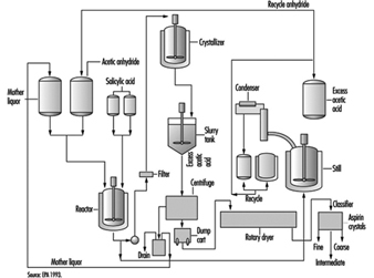
Pharmaceutical chemistry is becoming increasingly complex with multi-step processing, where the product from one step becomes a starting material for the next step, until the finished drug product is synthesized. Bulk chemicals which are intermediates of the finished product may be transferred between organic synthesis plants for various technical, financial and legal considerations. Most intermediates and products are produced in a series of batch reactions on a campaign basis. Manufacturing processes operate for discrete periods of time, before materials, equipment and utilities are changed to prepare for a new process. Many organic synthesis plants in the pharmaceutical industry are designed to maximize their operating flexibility, due to the diversity and complexity of modern medicinal chemistry. This is achieved by constructing facilities and installing process equipment that can be modified for new manufacturing processes, in addition to their utility requirements.
Multi-purpose reactors are the primary processing equipment in chemical synthesis operations (see figure 5). They are reinforced pressure vessels with stainless, glass or metal alloy linings. The nature of chemical reactions and physical properties of materials (e.g., reactive, corrosive, flammable) determine the design, features and construction of reactors. Multi-purpose reactors have external shells and internal coils which are filled with cooling water, steam or chemicals with special heat-transfer properties. The reactor shell is heated or cooled, based upon the requirements of the chemical reactions. Multi-purpose reactors have agitators, baffles and many inlets and outlets connecting them to other process vessels, equipment and bulk chemical supplies. Temperature-, pressure- and weight-sensing instruments are installed to measure and control the chemical process in the reactor. Reactors may be operated at high pressures or low vacuums, depending upon their engineering design and features and the requirements of the process chemistry.
Figure 5. Diagram of a chemical reactor in organic synthesis
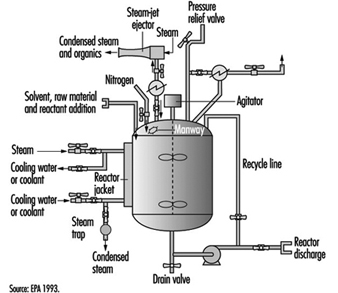
Heat exchangers are connected to reactors to heat or cool the reaction and condense solvent vapours when they are heated above their boiling point, creating a reflux or recycling of the condensed vapours. Air pollution control devices (e.g., scrubbers and impingers) can be connected to the exhaust vents on process vessels, reducing gas, vapour and dust emissions (EPA 1993). Volatile solvents and toxic chemicals may be released to the workplace or atmosphere, unless they are controlled during the reaction by heat exchangers or air control devices. Some solvents (see table 2) and reactants are difficult to condense, absorb or adsorb in air control devices (e.g., methylene chloride and chloroform) due to their chemical and physical properties.
Bulk chemical products are recovered or isolated by separation, purification and filtration operations. Typically, these products are contained in mother liquors, as dissolved or suspended solids in a solvent mixture. The mother liquors may be transferred between process vessels or equipment in temporary or permanent pipes or hoses, by pumps, pressurized inert gases, vacuum or gravity. Transferring materials is a concern due to the rates of reaction, critical temperatures or pressures, features of processing equipment and potential for leaks and spills. Special precautions to minimize static electricity are required when processes use or generate flammable gases and liquids. Charging flammable liquids through submerged dip tubes and grounding and bonding conductive materials and maintaining inert atmospheres inside process equipment reduce the risk of a fire or explosion (Crowl and Louvar 1990).
Worker health and safety
Many worker health and safety hazards are posed by synthesis operations. They include safety hazards from moving machine parts, pressurized equipment and pipes; heavy manual handling of materials and equipment; steam, hot liquids, heated surfaces and hot workplace environments; confined spaces and hazardous energy sources (e.g., electricity); and high noise levels.
Acute and chronic health risks may result from worker exposures to hazardous chemicals during synthesis operations. Chemicals with acute health effects can damage the eyes and skin, be corrosive or irritating to body tissues, cause sensitization or allergic reactions or be asphyxiants, causing suffocation or oxygen deficiency. Chemicals with chronic health effects may cause cancer, or damage the liver, kidneys or lungs or affect the nervous, endocrine, reproductive or other organ systems. Health and safety hazards may be controlled by implementing appropriate control measures (e.g., process modifications, engineering controls, administrative practices, personal and respiratory protective equipment).
Organic synthesis reactions may create major process safety risks from highly hazardous materials, fire, explosion or uncontrolled chemical reactions which impact the community surrounding the plant. Process safety can be very complex in organic synthesis. It is addressed in several ways: by examining the dynamics of chemical reactions, properties of highly hazardous materials, design, operation and maintenance of equipment and utilities, training of operating and engineering staff, and emergency preparedness and response of the facility and local community. Technical guidance is available on process hazard analysis and management activities to reduce the risks of chemical synthesis operations (Crowl and Louvar 1990; Kroschwitz 1992).
Biological and natural extraction
Large volumes of natural materials, such as plant and animal matter, may be processed to extract substances which are pharmacologically active (Gennaro 1990; Swarbick and Boylan 1996). In each step of the process, the volumes of materials are reduced by a series of batch processes, until the final drug product is obtained. Typically, processes are performed in campaigns lasting a few weeks, until the desired quantity of finished product is obtained. Solvents are used to remove insoluble fats and oils, thereby extracting the finished drug substance. The pH (acidity) of the extraction solution and waste products can be adjusted by neutralizing them with strong acids and bases. Metal compounds frequently serve as precipitating agents, and phenol compounds as disinfectants.
Worker health and safety
Some workers may develop allergic and/or skin irritation from handling certain plants. Animal matter may be contaminated with infectious organisms unless appropriate precautions are taken. Workers may be exposed to solvents and corrosive chemicals during biological and natural extraction operations. Fire and explosion risks are posed by storing, handling, processing and recovering flammable liquids. Moving mechanical parts; hot steam, water, surfaces and workplaces; and high noise levels are risks to worker safety.
Process safety issues are often reduced by the large volumes of plant or animal materials, and smaller scale of solvent extraction activities. Fire and explosion hazards, and worker exposures to solvents or corrosive or irritating chemicals may occur during extraction and recovery operations, depending upon the specific chemistry and containment of process equipment.
Pharmaceutical manufacturing of dosage forms
Drug substances are converted into dosage-form products before they are dispensed or administered to humans or animals. Active drug substances are mixed with pharmaceutical necessities, such as binders, fillers, flavouring and bulking agents, preservatives and antioxidants. These ingredients may be dried, milled, blended, compressed and granulated to achieve the desired properties before they are manufactured as a final formulation. Tablets and capsules are very common oral dosage forms; another common form is sterile liquids for injection or ophthalmic application. Figure 6 illustrates typical unit operations for manufacturing of pharmaceutical dosage-form products.
Figure 6. Pharmaceutical manufacturing of dosage-form products
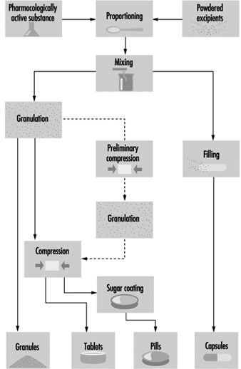
Pharmaceutical blends may be compressed by wet granulation, direct compression or slugging to obtain the desired physical properties, before their formulation as a finished drug product. In wet granulation, the active ingredients and excipients are wetted with aqueous or solvent solutions to produce course granules with enlarged particle sizes. The granules are dried, mixed with lubricants (e.g., magnesium stearate), disintegrants or binders, then compressed into tablets. During direct compression, a metal die holds a measured amount of the drug blend while a punch compresses the tablet. Drugs that are not sufficiently stable for wet granulation or cannot be directly compressed are slugged. Slugging or dry granulation blends and compresses relatively large tablets which are ground and screened to a desired mesh size, then recompressed into the final tablet. Blended and granulated materials may also be produced in capsule form. Hard gelatin capsules are dried, trimmed, filled and joined on capsule-filling machines.
Liquids may be produced as sterile solutions for injection into the body or administration to the eyes; liquids, suspensions and syrups for oral ingestion; and tinctures for application on the skin (Gennaro 1990). Highly controlled environmental conditions, contained process equipment and purified raw materials are required for manufacturing sterile liquids to prevent microbiological and particulate contamination (Cole 1990; Swarbick and Boylan 1996). Facility utilities (e.g., ventilation, steam and water), process equipment and workplace surfaces must be cleaned and maintained to prevent and minimize contamination. Water at high temperatures and pressures is used to destroy and filter bacteria and other contaminants from the sterile water supply when making solutions for injection. Parenteral liquids are injected by intradermal, intramuscular or intravenous administration into the body. These liquids are sterilized by dry or moist heat under high pressure with bacteria-retaining filters. Although liquid solutions for oral or topical use do not require sterilization, solutions to be administered to the eyes (ophthalmic) must be sterilized. Oral liquids are prepared by mixing the active drug substances with a solvent or preservative to inhibit mold and bacterial growth. Liquid suspensions and emulsions are produced by colloid mills and homogenizers, respectively. Creams and ointments are prepared by blending or compounding active ingredients with petrolatum, heavy greases or emollients before packaging in metal or plastic tubes.
Worker health and safety
Worker health and safety risks during pharmaceutical manufacturing are created by moving machine parts (e.g., exposed gears, belts and shafts) and hazardous energy sources (e.g., electrical, pneumatic, thermal, etc.); manual handling of material and equipment; high-pressure steam, hot water and heated surfaces; flammable and corrosive liquids; and high noise levels. Worker exposures to airborne dusts may occur during dispensing, drying, milling and blending operations. Exposure to pharmaceutical products is a particular concern when mixtures containing high proportions of active drug substances are handled or processed. Wet granulation, compounding and coating operations may create high worker exposures to solvent vapours.
Process safety issues primarily relate to the risks of fire or explosion during pharmaceutical manufacturing of dosage forms. Many of these operations (e.g., granulation, blending, compounding and drying) use flammable liquids, which may create flammable or explosive atmospheres. Since some pharmaceutical dusts are highly explosive, their physical properties should be examined before they are processed. Fluid bed drying, milling and slugging are a particular concern when they involve potentially explosive materials. Engineering measures and safe work practices reduce the risks of explosive dusts and flammable liquids (e.g., vapour- and dust-tight electrical equipment and utilities, grounding and bonding of equipment, sealed containers with pressure relief and inert atmospheres).
Control measures
Fire and explosion prevention and protection; process containment of hazardous substances, machine hazards and high noise levels; dilution and local exhaust ventilation (LEV); use of respirators (e.g., dust and organic vapour masks and, in some cases, powered air-purifying respirators or air-supplied masks and suits) and personal protective equipment (PPE); and worker training on workplace hazards and safe work practices are workplace control measures applicable during all of the various pharmaceutical manufacturing operations described below. Specific issues involve substituting less hazardous materials whenever possible during drug development and manufacturing. Also, minimizing material transfers, unsealed or open processing and sampling activities decreases the potential for worker exposures.
The engineering design and features of facilities, utilities and process equipment can prevent environmental pollution and reduce worker exposures to hazardous substances. Modern pharmaceutical manufacturing facilities and process equipment are reducing environmental, health and safety risks by preventing pollution and improving the containment of hazards. Worker health and safety and quality control objectives are achieved by improving the isolation, containment and cleanliness of pharmaceutical facilities and process equipment. Preventing worker exposures to hazardous substances and pharmaceutical products is highly compatible with the concurrent need to prevent workers from accidentally contaminating raw materials and finished products. Safe work procedures and good manufacturing practices are complementary activities.
Facility design and process-engineering issues
The engineering design and features of pharmaceutical facilities and process equipment influences worker health and safety. The construction materials, process equipment and housekeeping practices greatly affect the cleanliness of the workplace. Dilution and LEV systems control fugitive vapours and dust emissions during manufacturing operations. Fire and explosion prevention and protection measures (e.g., vapour- and dust-tight electrical equipment and utilities, extinguishing systems, fire and smoke detectors and emergency alarms) are needed when flammable liquids and vapours are present. Storage and handling systems (e.g., storage vessels, portable containers, pumps and piping) are installed to move liquids within pharmaceutical manufacturing facilities. Hazardous solids can be handled and processed in enclosed equipment and vessels, individual bulk containers (IBCs) and sealed drums and bags. The isolation or containment of facilities, process equipment and hazardous materials promotes worker health and safety. Mechanical hazards are controlled by installing barrier guards on moving machine parts.
The process equipment and utilities may be controlled by manual or automatic means. In manual plants, chemical operators read instruments and control process equipment and utilities near the process equipment. In automated plants, the process equipment, utilities and control devices are controlled by distributed systems, allowing them to be operated from a remote location such as a control room. Manual operations are often employed when materials are charged or transferred, products are discharged and packaged and when maintenance is performed or nonroutine conditions arise. Written instructions should be prepared, to describe standard operating procedures as well as worker health and safety hazards and control measures.
Verification of workplace controls
Workplace control measures are evaluated periodically to protect workers from health and safety hazards and minimize environmental pollution. Many manufacturing processes and pieces of equipment are validated in the pharmaceutical industry to ensure the quality of products (Cole 1990; Gennaro 1990; Swarbick and Boylan 1996). Similar validation practices may be implemented for workplace control measures to ensure that they are effective and reliable. Periodically, process instructions and safe work practices are revised. Preventive maintenance activities identify when process and engineering equipment may fail, thereby precluding problems. Training and supervision informs and educates workers about environmental, health and safety hazards, reinforcing safe work practices and the use of respirators and personal protective equipment. Inspection programmes examine whether safe workplace conditions and work practices are maintained. This includes inspecting respirators and to ensure they are properly selected, worn and maintained by workers. Audit programmes review the management systems for identifying, evaluating and controlling environmental, health and safety hazards.
Pharmaceutical unit operations
Weighing and dispensing
Weighing and dispensing of solids and liquids is a very common activity throughout the pharmaceutical industry (Gennaro 1990). Usually workers dispense materials by hand-scooping solids and pouring or pumping liquids. Weighing and dispensing are often performed in a warehouse during bulk chemical production or in a pharmacy during pharmaceutical dosage-form manufacturing. Due to the likelihood of spills, leaks and fugitive emissions during weighing and dispensing, proper workplace control measures are necessary to protect workers. Weighing and dispensing should be performed in a partitioned workplace area with good dilution ventilation. The work surfaces in areas where materials are weighed and dispensed should be smooth and sealed, permitting their proper cleaning. LEV with backdraft or sidedraft hoods prevents the release of air contaminants when weighing and dispensing dusty solids or volatile liquids (Cole 1990). Weighing and dispensing highly toxic materials may require additional control measures such as laminar ventilation hoods or isolation devices (e.g., glove boxes or glove bags) (Naumann et al. 1996).
Charging and discharging solids and liquids
Solids and liquids are frequently charged and discharged from containers and process equipment in pharmaceutical manufacturing operations (Gennaro 1990). Charging and discharging of materials are often performed manually by workers; however, other methods are employed (e.g., gravity, mechanical or pneumatic transfer systems). Contained process equipment, transfer systems and engineering controls prevent worker exposures during charging and discharging of highly hazardous materials. Gravity charging from enclosed containers and vacuum, pressure and pumping systems eliminate fugitive emissions during charging and discharging operations. LEV with flanged inlets captures fugitive dusts and vapours which are released at open transfer points.
Liquid separations
Liquids are separated based upon their physical properties (e.g., density, solubility and miscibility) (Kroschwitz 1992). Liquid separations are commonly performed during bulk chemical production and pharmaceutical manufacturing operations. Hazardous liquids should be transferred, processed and separated in closed vessels and piping systems to reduce worker exposures to liquid spills and airborne vapours. Eyewashes and safety showers should be located near operations where hazardous liquids are transferred, processed or separated. Spill control measures and fire and explosion prevention and protection are needed when using flammable liquids.
Transferring liquids
Liquids are often transferred between storage vessels, containers and process equipment during pharmaceutical manufacturing operations. Ideally, facility and manufacturing processes are designed to minimize the need for transferring hazardous materials, thereby decreasing the chance of spills and worker exposures. Liquids may be transferred between process vessels and equipment through manifold stations, areas where many pipe flanges are located close together (Kroschwitz 1992). This allows temporary connections to be made between piping systems. Spills, leaks and vapour emissions may occur at manifold stations; therefore proper gaskets and tight seals on hoses and pipes are needed to prevent environmental pollution and workplace releases. Drainage systems with sealed tanks or sumps capture spilled liquids so they can be reclaimed and recovered. Sealed vessels and containers and piping systems are highly desirable when transferring large volumes of liquids. Special precautions should be taken when using inert gases to pressurize transfer lines or process equipment, since this may increase the release of volatile organic compounds (VOCs) and hazardous air pollutants. Recirculation or condensation of exhaust gases and vapours reduces air pollution.
Filtration
Solids and liquids are separated during filtration operations. Filters have different designs and features with varying containment and control of liquids and vapours (Kroschwitz 1992; Perry 1984). When open filters are used for hazardous materials, workers may be exposed to liquids, wet solids, vapours and aerosols during loading and unloading operations. Closed process equipment can be used to filter highly hazardous materials, reducing vapour emissions and preventing worker exposures (see figure 7). Filtration should be performed in areas with spill control and good dilution and LEV. Volatile solvent vapours can be exhausted through vents on sealed process equipment and controlled by air emissions devices (e.g., condensers, scrubbers and adsorbers).
Figure 7. A sparkler filter
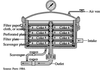
Compounding
Solids and liquids are mixed in compounding operations to produce solutions, suspensions, syrups, ointments and pastes. Contained process equipment and transfer systems are recommended when compounding highly hazardous materials (Kroschwitz 1992; Perry 1984). Buffering agents, detergents and germicides that are neutralizing, cleaning and biocidal agents may be hazardous to workers. Eyewashes and safety showers reduce injuries, if workers accidentally contact corrosive or irritating substances. Due to the wet surfaces in compounding areas, workers need to be protected from electrical hazards of equipment and utilities. Thermal hazards are posed by steam and hot water during compounding and cleaning activities. Worker injuries from burns and falls are prevented by installing insulation on hot surfaces and maintaining dry non-slip floors.
Figure 8. A high steam granulator
Figure MISSING
Granulation
Dry and wet solids are granulated to change their physical properties. Granulators have different designs and features with varying containment and control of mechanical hazards and airborne dusts and vapours (Perry 1984; Swarbick and Boylan 1996). Enclosed granulators can be vented to air-control devices, reducing emissions of solvent vapours or dusts to the workplace and atmosphere (see figure 8). Material-handling concerns arise when loading and unloading granulators. Mechanical equipment (e.g., elevated platforms, lift tables and pallet jacks) assists workers to perform heavy manual tasks. Eyewashes and safety showers are needed, if workers accidentally contact solvents or irritating dusts.
Figure 9. A rotary vacuum dryer
Figure MISSING
Drying
Water- or solvent-wet solids are dried during many pharmaceutical manufacturing operations. Dryers have different designs and features with varying containment and control of vapours and dusts (see figure 9). Flammable solvent vapours and explosive airborne dusts may create flammable or explosive atmospheres; explosion relief venting is particularly important on contained dryers. Dilution and LEV reduces the risk of fire or explosion, in addition to controlling worker exposures to solvent vapours when handling wet cakes, or to airborne dusts when unloading dried products. Heavy material handling may be involved when loading or unloading dryer trays, bins or containers (see figure 10). Mechanical equipment (e.g., drum jacks, lifts and work platforms) assists these manual tasks. Eyewashes and safety showers should be located nearby, in case workers accidentally contact solvents and dusts.
Figure 10. A vacuum shelf dryer
Figure MISSING
Milling
Dry solids are milled to change their particle characteristics and produce free-flowing powders. Mills have different designs and features with varying containment and control of mechanical hazards and airborne dusts (Kroschwitz 1992; Perry 1984). Prior to milling materials, their physical properties and hazards should be reviewed or tested. Explosion prevention and protection measures involve installing dust-tight electrical equipment and utilities, grounding and bonding equipment and accessories to eliminate electrostatic sparking, installing safety relief valves on enclosed mills, and constructing blast relief panels in walls. These measures may be necessary due to the explosivity of some drug substances and excipients, high dust levels and energies associated with milling operations.
Blending
Dry solids are blended to produce homogeneous mixtures. Blenders have different designs and features with varying containment and control of mechanical hazards and airborne dusts (Kroschwitz 1992; Perry 1984). Worker exposures to drug substances, excipients and blends may occur when loading and unloading blending equipment. LEV with flanged inlets reduces fugitive dust emissions during blending. Heavy material handling may be required when charging and discharging solids from blenders. Mechanical equipment (e.g., work platforms, hoists and drum and pallet jacks) reduces the physical demands of heavy material handling.
Compression
Dry solids are compressed or slugged to compact them, changing their particle properties. Compression equipment has different designs and features with varying containment and control of mechanical hazards and airborne dusts (Gennaro 1990; Swarbick and Boylan 1996). Compression equipment may pose serious mechanical hazards if inadequately guarded. High noise levels may also be produced by compression and slugging operations. Enclosing impact sources, isolating vibrating equipment, rotating workers and using hearing-protective devices (e.g., ear muffs and plugs) reduce the impact of noise exposures.
Figure 11. Tablet press with load hopper and spiral dust pickups for product recovery
Figure MISSING
Solid dosage-form manufacturing
Tablets and capsules are the most common oral dosage forms. Compressed or moulded tablets contain mixtures of drug substances and excipients. These tablets may be uncoated or coated with solvent mixtures or aqueous solutions. Capsules are soft or hard gelatin shells. Tablet presses (see figure 11), tablet-coating equipment and capsule-filling machines have different designs and features with varying containment and control of mechanical hazards and airborne dusts (Cole 1990). Workers may be exposed to solvent vapours when spray-coating tablets. Modern tablet-coating equipment is highly contained; however, LEV can be installed in older open coating pans to control fugitive solvent vapours. Tablet-coating equipment can be vented to air emission devices to control VOCs from the process (see figure 12). Whenever possible, recovered solvents should be reused by the process or aqueous mixtures substituted for solvent mixtures for tablet coating. Modern tablet presses and capsule-filling machines are enclosed by interlocked panels, reducing the hazards of fast-moving parts, high noise levels and dust emissions during their operation. Hearing-protective devices can reduce worker noise exposures during tablet and capsule operations.
Figure 12. A tablet coating machine
Figure MISSING
Sterile manufacturing
Sterile products are manufactured in pharmaceutical manufacturing plants with modular design (see figure 13), clean workplace and equipment surfaces, and high efficiency particulate air (HEPA) filtered ventilation systems (Cole 1990; Gennaro 1990). The principles and practices of controlling contamination in sterile liquid manufacturing are similar to those in the microelectronics industry. Workers wear protective clothing to prevent them from contaminating products during sterile manufacturing operations. Sterile pharmaceutical technologies to control contamination involve freeze-drying products, using liquid germicides and sterilizing gases, installing laminar flow ventilation, isolating modules with differential air pressures and containing manufacturing and filling equipment.
Figure 13. Diagram of a sterile liquid manufacturing facility

Chemical hazards are posed by toxic germicides (e.g., formaldehyde and glutaraldehyde) and sterilizing gases (i.e., ethylene oxide). Whenever possible, less hazardous agents should be selected (e.g., alcohols, ammonium compounds). Sterilization of raw materials and equipment may be performed by high-pressure steam or toxic gases (i.e., diluted ethylene oxide gas mixtures) (Swarbick and Boylan 1996). Sterilization vessels can be located in separate areas with remote instrument and control systems, non-recirculated air and LEV to extract toxic gas emissions. Workers should be trained on standard operating instructions, safe work practices and appropriate emergency response. Gas sterilization chambers should be fully evacuated under vacuum and purged with air to minimize fugitive workplace emissions before sterilized goods are removed. Gas emissions from sterilization chambers can be vented to air control devices (e.g., carbon adsorption or catalytic converters) to reduce atmospheric emissions. Occupational hygiene monitoring measures worker exposures to chemical germicides and sterilizing gases, helping to assess the adequacy of control measures. Safety hazards involve high-pressure steam and hot water, moving machine parts in washing, filling, capping and packaging equipment, high noise levels and repetitive manual tasks.
Cleaning and maintenance activities
Non-routine tasks may occur when cleaning, repairing and maintaining equipment, utilities and workplaces. Although unique hazards may arise during non-routine tasks, recurring health and safety concerns are encountered. Workplace and equipment surfaces may be contaminated by hazardous materials and drug substances, requiring them to be cleaned before unprotected workers conduct servicing or maintenance work. Cleaning is performed by washing or wiping liquids and sweeping or vacuuming dusts. Dry sweeping and blowing solids with compressed air are not recommended, since they create high worker exposures to airborne dusts. Wet mopping and vacuuming reduce worker exposures to dusts during cleaning activities. Vacuum cleaners with HEPA filters may be needed when cleaning hazardous substances and high-potency drugs. Explosion-proof equipment and conductive materials may be required in vacuum systems for explosive dusts. Eyewashes and safety showers and PPE reduce the effect of workers’ accidental contact with corrosive and irritating detergents and cleaning liquids.
Hazardous mechanical, electrical, pneumatic or thermal energy may need to be released or controlled before equipment and utilities are serviced, repaired or maintained. Contract workers may perform special production or engineering tasks in pharmaceutical plants without adequate training on safety precautions. Careful supervision of contract workers is important, so they do not violate safety rules or perform work that creates a fire, explosion or other serious health and safety hazards. Special contractor safety programmes are required when working with highly hazardous materials (e.g., toxic, reactive, flammable or explosive) and processes (e.g., exothermic or high pressure) in bulk pharmaceutical and dosage-form manufacturing facilities.
Packaging
Pharmaceutical packaging operations are performed with a series of integrated machines and repetitive manual tasks (Gennaro 1990; Swarbick and Boylan 1996). Finished dosage-form products may be packaged in many different types of containers (e.g., plastic or glass bottles, foil blister packs, pouches or sachets, tubes and sterile vials). The mechanical equipment fills, caps, labels, cartons and packs the finished products in shipping containers. Worker proximity to packaging equipment necessitates barrier guarding on moving machine parts, accessible control switches and emergency stop cables and employee training on machine hazards and safe work practices. Enclosure and isolation of equipment reduces sound and vibration levels in packaging areas. Use of hearing-protective devices (e.g., ear muffs and plugs) reduces worker exposures to noise. Good industrial design promotes the productivity, comfort and safety of employees, by addressing ergonomic hazards from poor body postures, material handling and highly repetitive tasks.
Laboratory operations
Laboratory operations in the pharmaceutical industry are diverse. They may pose biological, chemical and physical hazards, depending upon the specific agents, operations, equipment and work practices employed. Major distinctions exist between labs which conduct scientific research and product and process development and those which evaluate quality assurance and control activities (Swarbick and Boylan 1996). Lab workers may conduct scientific research to discover drug substances, develop manufacturing processes for bulk chemical and dosage-form products or analyze raw materials, intermediates and finished products. Lab activities should be evaluated individually, although good lab practices apply to many situations (National Research Council 1981). Clearly defined responsibilities, training and information, safe work practices and control measures and emergency response plans are important means for effectively managing environmental, health and safety hazards.
The health and safety hazards of flammable and toxic materials are reduced by minimizing their inventories in labs and storing them in separate cabinets. Lab assays and operations which may release air contaminants can be performed in ventilated exhaust fume hoods to protect workers. Biological safety hoods provide downward and inward laminar flow, preventing the release of micro-organisms (Gennaro 1990; Swarbick and Boylan 1996). Worker training and information describes the hazards of lab work, safe work practices and proper emergency response to fires and spills. Food and beverages should not be consumed in lab areas. Lab safety is enhanced by requiring supervisors to approve and manage highly hazardous operations. Good lab practices separate, treat and dispose of biological and chemical wastes. Physical hazards (e.g., radiation and electromagnetic energy sources) are often certified and operated, according to specific regulations.
General Health and Safety Hazards
Ergonomics and material handling
The materials shipped, stored, handled, processed and packaged in the pharmaceutical industry range from large quantities of raw materials to small packages containing pharmaceutical products. Raw materials for bulk chemical production are shipped in bulk containers (e.g., tank trucks, rail cars), metal and fibre drums, reinforced paper and plastic bags. Pharmaceutical production uses smaller quantities of raw materials due to the reduced scale of the operations. Material-handling devices (e.g., fork-lift trucks, pallet lifts, vacuum hoists and drum jacks) assist material handling during warehousing and production operations. Heavy manual work may create ergonomic risks when moving materials and equipment if mechanical devices are not available. Good industrial engineering and facility management practices reduce injuries from material handling by improving the design and features of equipment and the workplace and decreasing the size and weight of containers (Cole 1990). Engineering control measures (e.g., ergonomic design of tools, materials and equipment) and administrative practices (e.g., rotating workers, providing worker training) reduce the risks of cumulative trauma injuries during highly repetitive production and packaging operations.
Machine guarding and control of hazardous energy
Unguarded moving machine parts in pharmaceutical manufacturing and packaging equipment create mechanical hazards. Exposed “crush and nip points” in open equipment may seriously injure workers. Mechanical hazards are exacerbated by the large numbers and different designs of equipment, crowded workplace conditions and frequent interactions between workers and equipment. Interlocked guards, control switches, emergency stop devices and operator training are important means of reducing mechanical hazards. Loose hair, long-sleeved clothing, jewellery or other objects may become trapped in equipment. Routine inspection and repair activities identify and control mechanical hazards during production and packaging operations. Hazardous electrical, pneumatic and thermal energy must be released or controlled before working on active equipment and utilities. Workers are protected from sources of hazardous energy by implementing lockout/tagout procedures.
Noise exposures
High sound levels may be generated by manufacturing equipment and utilities (e.g., compressed air, vacuum sources and ventilation systems). Due to the enclosed design of pharmaceutical workplace modules, workers are often located close to machines during manufacturing and packaging operations. Workers observe and interact with production and packaging equipment, thereby increasing their exposure to noise. Engineering methods reduce sound levels by modifying, enclosing and dampening noise sources. Employee rotation and use of hearing-protective devices (e.g., ear muffs and plugs) reduce workers’ exposure to high noise levels. Comprehensive hearing conservation programmes identify noise sources, reduce workplace sound levels, and train workers on the hazards of noise exposure and proper use of hearing-protective devices. Noise monitoring and medical surveillance (i.e., audiometry) assess worker exposures to noise and their resulting loss of hearing. This helps to identify noise problems and evaluate the adequacy of corrective measures.
Solvent vapour and potent compound exposures
Special concerns may arise when workers are exposed to toxic solvent vapours and potent drugs as airborne dusts. Worker exposures to solvent vapours and potent compounds may occur during various manufacturing operations, which need to be identified, evaluated and controlled to ensure that workers are protected. Engineering controls are the preferred means of controlling these exposures, due to their inherent effectiveness and reliability (Cole 1990; Naumann et al. 1996). Enclosed process equipment and material handling systems prevent worker exposures, while LEV and PPE supplement these measures. Increased facility and process containment is needed for controlling highly toxic solvents (e.g., benzene, chlorinated hydrocarbons, ketones) and potent compounds. Positive-pressure respirators (e.g., powered-air purifying and supplied-air) and PPE are needed when highly toxic solvents and potent compounds are handled and processed. Special concerns are posed by operations where high levels of solvent vapours (e.g., compounding, granulating and tablet coating) and dusts (e.g., drying, milling and blending) are generated. Locker and shower rooms, decontamination practices and good sanitary practices (e.g., washing and showering) are necessary to prevent or minimize the effects of worker exposures inside and outside the workplace.
Process safety management
Process safety programmes are implemented in the pharmaceutical industry due to the complex chemistry, hazardous materials and operations in bulk chemical manufacturing (Crowl and Louvar 1990). Highly hazardous materials and processes may be employed in multi-step organic synthesis reactions to produce the desired drug substance. The thermodynamics and kinetics of these chemical reactions must be evaluated, since they may involve highly toxic and reactive materials, lachrymators and flammable or explosive compounds.
Process safety management involves conducting physical hazard testing of materials and reactions, performing hazard analysis studies to review the process chemistry and engineering practices, examining preventive maintenance and mechanical integrity of the process equipment and utilities, implementing worker training and developing operating instructions and emergency response procedures. Special engineering features for process safety include selecting proper pressure-rated vessels, installing isolation and suppression systems, and providing pressure relief venting with catch tanks. Process safety management practices are similar in the pharmaceutical and chemical industries when manufacturing bulk pharmaceuticals as speciality organic chemicals (Crowl and Louvar 1990; Kroschwitz 1992).
Environmental Issues
The different pharmaceutical manufacturing processes each have their own environmental issues, as discussed below.
Fermentation
Fermentation generates large volumes of solid waste which contains mycelia and spent filter cakes (EPA 1995; Theodore and McGuinn 1992). Filter cakes contain mycelia, filter media and small amounts of nutrients, intermediates and residual products. These solid wastes are typically non-hazardous, yet they may contain solvents and small amounts of residual chemicals depending upon the specific chemistry of the fermentation process. Environmental problems may develop if fermentation batches become infected with a viral phage which attacks the micro-organisms in the fermentation process. Although phage infections are rare, they create a significant environmental problem by generating large amounts of waste broth.
Spent fermentation broth contains sugars, starches, proteins, nitrogen, phosphates and other nutrients with high biochemical oxygen demand (BOD), chemical oxygen demand (COD) and total suspended solids (TSS) with pH values ranging from 4 to 8. Fermentation broths can be treated by microbiological wastewater systems, after the effluent is equalized to promote the stable operation of the treatment system. Steam and small amounts of industrial chemicals (e.g., phenols, detergents and disinfectants) maintain the sterility of the equipment and products during fermentation. Large volumes of moist air are exhausted from fermentors, containing carbon dioxide and odours which may be treated before they are emitted to the atmosphere.
Organic synthesis
Wastes from chemical synthesis are complex due to the variety of hazardous materials, reactions and unit operations (Kroschwitz 1992; Theodore and McGuinn 1992). Organic synthesis processes may generate acids, bases, aqueous or solvent liquors, cyanides and metal wastes in liquid or slurry form. Solid wastes may include filter cakes containing inorganic salts, organic by-products and metal complexes. Waste solvents in organic synthesis are usually recovered by distillation and extraction. This allows the solvents to be reused by other processes and reduces the volume of liquid hazardous wastes to be disposed of. Residues from distillation (still bottoms) need to be treated before they are disposed. Typical treatment systems include steam stripping to remove solvents, followed by microbiological treatment of other organic substances. Volatile organic and hazardous substance emissions during organic synthesis operations should be controlled by air pollution control devices (e.g., condensers, scrubbers, venturi impingers).
Waste water from synthesis operations may contain aqueous liquors, wash water, discharges from pumps, scrubbers and cooling systems, and fugitive leaks and spills (EPA 1995). This waste water may contain many organic and inorganic substances with different chemical compositions, toxicities and biodegradabilities. Trace amounts of raw materials, solvents and by-products may be present in aqueous mother liquors from crystallizations and wash layers from extractions and equipment cleaning. These waste waters are high in BOD, COD and TSS, with varying acidity or alkalinity and pH values ranging from 1 to 11.
Biological and natural extraction
Spent raw materials and solvents, wash water and spills are the primary sources of solid and liquid wastes (Theodore and McGuinn 1992). Organic and inorganic chemicals may be present as residues in these waste streams. Usually, waste waters have low BOD, COD and TSS, with relatively neutral pH values ranging from 6 to 8.
Pharmaceutical manufacturing of dosage forms
Pharmaceutical manufacturing of dosage-form products generates solid and liquid wastes during cleaning and sterilization, and from leaks and spills and rejected products (Theodore and McGuinn 1992). Drying, milling and blending operations generate atmospheric and fugitive dust emissions. These emissions can be controlled and recycled to the manufacturing of dosage form products; however, quality control practices may prevent this if other residues are present. When solvents are used during wet granulation, compounding and tablet coating, VOCs and hazardous air pollutants may be released to the atmosphere or in the workplace as process or fugitive emissions. Waste waters may contain inorganic salts, sugars, syrups and traces of drug substances. These waste waters usually have low BOD, COD and TSS, with neutral pH values. Some antiparasitic or anti-infective drugs for humans and animals may be toxic to aquatic organisms, requiring special treatment of liquid wastes.
Environmental pollution prevention
Waste minimization and pollution prevention
Good engineering and administrative practices minimize the environmental impact of bulk chemical production and pharmaceutical manufacturing operations. Pollution prevention employs modifying processes and equipment, recycling and recovering materials and maintaining good housekeeping and operating practices (Theodore and McGuinn 1992). These activities enhance the management of environmental issues, as well as worker health and safety.
Process modifications
Processes may be modified to reformulate products by using materials that are less hazardous or persistent or changing manufacturing operations to reduce air emissions, liquid effluents and solid wastes. Reducing the amount and toxicity of wastes is wise, since it improves the efficiency of manufacturing processes and reduces the costs and impacts of waste disposal. Government drug approval regulations may limit the ability of pharmaceutical manufacturers to change hazardous materials, manufacturing processes, equipment and facilities (Spilker 1994). Drug manufacturers must anticipate the environmental, health and safety impacts of selecting hazardous materials and designing manufacturing process at an early stage. It becomes increasingly difficult to make changes during the later stages of drug development and regulatory approval, without considerable loss of time and expense.
It is very desirable to develop manufacturing processes with less hazardous solvents. Ethyl acetate, alcohols and acetone are preferable to highly toxic solvents such as benzene, chloroform and trichloroethylene. Whenever possible, some materials should be avoided due to their physical properties, ecotoxicity or persistence in the environment (e.g., heavy metals, methylene chloride) (Crowl and Louvar 1990). Substituting aqueous washes for solvents during filtrations in bulk chemical production reduces liquid wastes and vapour emissions. Also, substituting aqueous for solvent-based solutions during tablet coating reduces environmental, health and safety concerns. Pollution prevention is promoted by improving and automating process equipment, as well as performing routine calibration, servicing and preventive maintenance. Optimizing organic synthesis reactions increases product yields, often decreasing the generation of wastes. Incorrect or inefficient temperature, pressure and material control systems cause inefficient chemical reactions, creating additional gaseous, liquid and solid wastes.
The following are examples of process modifications in bulk pharmaceutical production (Theodore and McGuinn 1992):
- Minimize the quantities of hazardous materials used and select materials whose wastes can be controlled, recovered and recycled, whenever possible.
- Develop and install systems for recycling raw materials (e.g., solvents), intermediates, wastes and utility materials (e.g., cooling water, heat transfer liquids, lubricants, steam condensate).
- Examine reactants, solvents and catalysts to optimize the efficiency of chemical reactions.
- Modify the design and features of processing equipment to minimize pollution and wastes.
- Improve processes to maximize product yields and desired properties, eliminating additional processing (e.g., re-crystallization, drying and milling).
- Consider using multi-purpose equipment (e.g., reactors, filters and dryers) to reduce pollution and wastes during transfers, cleaning and additional process steps.
- Use appropriate instruments, automated control systems and computer programs to maximize the efficiency of processes and reduce pollution and wastes.
Resource recovery and recycling
Resource recovery uses waste products and reclaims materials during processing by separating waste impurities from desired materials. Solid wastes from fermentation (e.g., mycelia) may be added to animal feeds as a nutritional supplement or as soil conditioners and fertilizers. Inorganic salts may be recovered from chemical liquors produced during organic synthesis operations. Spent solvents are often recycled by separation and distillation. Air emission control devices (e.g., condensers, compression and refrigeration equipment) greatly reduce emissions of volatile organic compounds to the atmosphere (EPA 1993). These devices capture solvent vapours by condensation, enabling the reuse of solvents as raw materials or for cleaning vessels and equipment. Scrubbers neutralize or absorb acid, caustic and soluble gases and vapours, discharging their effluents to waste treatment systems.
Recycled solvents may be reused as media for performing reactions and extractions, and cleaning operations. Different types of solvents should not be mixed, since this reduces their ability to be recycled. Some solvents should be segregated during processing (e.g., chlorinated and non-chlorinated, aliphatic and aromatic, aqueous and flammable solvents). Dissolved and suspended solids are extracted or separated from the solvents, before the solvents are recovered. Laboratory analysis identifies the composition and properties of waste solvents and recycled raw materials. Many new waste prevention and control technologies are being developed for solid, liquid and gaseous wastes.
General housekeeping and operating practices
Written operating procedures, material-handling instructions and waste management practices reduce the generation and improve the treatment of wastes (Theodore and McGuinn 1992). Good operating and housekeeping practices identify specific responsibilities for generating, handling and treating wastes. Training and supervision of operating staff increases their ability to improve and maintain efficient manufacturing and waste management operations. Workers should be trained on the hazards of waste management practices and the proper means of responding to emergency spills, leaks and fugitive emissions. Worker training should address material handling, cleaning or neutralizing wastes and wearing respirators and PPE. Spill and leak detection devices prevent pollution by routinely monitoring production equipment and utilities, identifying and controlling fugitive emissions and leaks. These activities may be successfully integrated with preventive maintenance practices to clean, calibrate, replace and repair equipment that creates pollution.
Written instructions describing normal operating procedures, as well as start-up, shut-down and emergency procedures, prevent pollution and reduce risks to worker health and safety. Careful management of material inventories decreases the excessive purchasing of raw materials and generation of wastes. Computer systems can assist the effective management of plant operations, maintenance practices and material inventories. Automatic weighing, monitoring and alarm systems can be installed to improve the management of materials and equipment (e.g., storage tanks, process equipment and waste treatment systems). Modern instrument and control systems often increase the productivity of operations, reducing pollution and health and safety hazards. Comprehensive pollution prevention programmes examine all wastes generated at a facility and examine the options for eliminating, reducing or treating them. Environmental audits examine the strengths and weaknesses of pollution prevention and waste management programmes, seeking to optimize their performance.
More...
Case Study: Effects of Synthetic Oestrogens on Pharmaceutical Workers: A United States Example
Background
Oestrogens used in the pharmaceutical industry can generally be classified as natural or synthetic and as steroidal or non-steroidal. All steroidal oestrogens, both natural (e.g., oestrone) and synthetic (e.g., ethynyloestradiol and moestranol) have a typical multi-ring structure, as depicted in figure 6 Diethylstilboestrol (DES) and dienoestrol are examples of the non-steroidal oestrogens. The principal uses of oestrogenic compounds are in oral contraceptive tablets and tablets intended for oestrogen replacement therapy. The pure compounds (naturally derived or synthesized) are no longer manufactured in the United States, but are imported.
Figure 1. Examples of steroidal and non-steroidal oestrogen structure

Manufacturing processes
The following description is a generalized, and composite, description of the manufacturing process used in many US pharmaceutical companies. Specific product processes may not follow the flow exactly as described below; some steps may be absent in some processes, and, in other cases, additional steps may be present that are not described here.
As with most dry-product drugs, pharmaceutical products made from oestrogenic compounds are manufactured in a step-wise batch operation (figure 2). The manufacturing steps begin with the assembly and pre-weighing of both active ingredients and excipients (inactive ingredients) in an isolated room under local exhaust ventilation. When needed, the ingredients are moved to a blending room equipped with mechanical blenders. Excipients are usually loaded dry from a hopper above the blender. The active ingredients are almost always dissolved first in an alcohol, and are added manually or are fed through tubing through the side of the blender. The initial blending of the ingredients is done in a wet state. At the end of the wet blending process, the granulation is typically moved to a wet mill, where particles in the mix are reduced to a specific size. The milled granulation is then dried using a fluid bed drier or is tray-dried in ovens designed for the purpose. The dried granulation may or may not undergo the addition of a lubricant before dry-blending and/or dry-milling, depending on the specific product and process. The final granulation, ready to be made into tablets, is then stored in sealed containers. The raw materials and granulation, and sometimes the intermediate products, are typically sampled and assayed by quality-control personnel prior to being moved to the next process step.
Figure 2. Typical oral contraceptive tablet manufacturing process flow
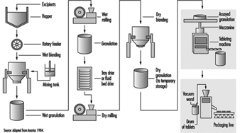
When needed, the granulation is moved to a compression room, where it is made into tablets by means of a tablet press. The granulation is typically fed from the storage container (typically a plastic-lined fibre drum or a lined stainless steel container) into the tablet press hopper by gravity or pneumatically by means of a vacuum wand. Formed tablets exit from the machine through tubing at the side, and drop into plastic-lined drums. When filled, the drums are sampled and inspected. After assay by quality-control personnel, the drums are sealed, stored and staged for packaging operations. Some tablets also undergo a coating process, in which layers of edible wax and sometimes sugars are used to seal the tablet.
The tablets are packaged by sealing them in blister packs or bottled, depending on the nature of the product. In this process, the containers of tablets are moved to the packaging area. The tablets may be manually scooped into the packaging machine hopper or fed by means of a vacuum wand. The tablets are then either immediately sealed between layers of aluminium foil and plastic film (blister-packaging) or they are bottled. The blister packs or bottles are then conveyed along a line on which they are inspected and placed in pouches or boxed with appropriate inserts.
Health effects on male and female pharmaceutical workers
Reports of occupational exposures and the effects on males have been relatively few, compared with the considerable literature that exists regarding acute and chronic effects of oestrogens in women as a result of non-occupational exposures. The non-occupational literature is primarily a result of widespread contraceptive and other medical uses of oestrogenic pharmaceuticals (but also environmental pollutants with oestrogenic properties, such as the organochlorines) and focuses particularly on the relationships between that exposure and a variety of human cancers, such as that of the endometrium, cervix and breast in women (Hoover 1980; Houghton and Ritter 1995). In the occupational literature, the hyperoestrogenic syndrome in both male and female workers has been associated with exposures to DES and its derivatives, natural or conjugated oestrogens, hexoestrol and its derivatives and steroidal synthetics such as ethynyloestradiol and moestranol. Shortly after the initiation of commercial production of oestrogens, reports began to surface of their effects, such as gynaecomastia (abnormal enlargement of the breasts in a male) and decreased libido among male workers, and menstrual disorders (increased flow or inter-menstrual spotting) among female workers (Scarff and Smith 1942; Fitzsimons 1944; Klavis 1953; Pagani 1953; Watrous 1947; Watrous and Olsen 1959; Pacynski et al. 1971; Burton and Shumnes 1973; Meyer, Peteet and Harrington 1978; Katzenellenbogen 1956; Dunn 1940; Stoppleman and van Valkenburg 1955; Goldzieher and Goldzieher 1949; Fisk 1950). There have also been a few reports of toxicity syndrome associated with some progoestogenic compounds, including acetoxyprogoesterone (Suciu et al. 1973), and vinyloestrenolone in combination with ethynyloestradiol (Gambini, Farine and Arbosti 1976).
A total of 181 cases of hyperoestrogenism in both males and females (occurring over the period 1940–1978) were recorded and reported by company physicians in 10 pharmaceutical companies (13 plant sites) in the United States (Zaebst, Tanaka and Haring 1980). The 13 plant sites included 9 sites manufacturing primarily oral contraceptives containing various synthetic oestrogens and progoestogens, one firm manufacturing oestrogen replacement pharmaceuticals from natural conjugated oestrogens and one firm manufacturing pharmaceuticals from DES (which had in earlier years also synthesized DES).
Investigators from the US National Institute for Occupational Safety and Health (NIOSH) conducted a pilot industrial hygiene and medical study in 1984 of male and female workers in two plants (Tanaka and Zaebst 1984). Measurable exposures were documented to both moestranol and natural conjugated oestrogens, both inside and outside the respiratory protective equipment used. However, no statistically significant changes in oestrogen-stimulated neurophysins (ESN), corticosteroid-binding globulins (CBG), testosterone, thyroid function, blood-clotting factors, liver function, glucose, blood lipids or gonadotropic hormones were noted in these workers. On physical examination, no adverse physical changes were noted in either male or female workers. However, in the plant using moestranol and norethindrone to manufacture oral contraceptive tablets, serum ethynyloestradiol levels appeared to show possible oestrogen exposure and absorption despite the use of respirators. Inside-respirator air samples obtained at this plant suggested less effective workplace protection factors than expected.
Hyperoestrogenic symptoms in males reported in these studies have included nipple sensitivity (manifested as tingling or tenderness of the nipple) or a feeling of pressure in the breast area and, in some cases, breast hyperplasia and gynaecomastia. Additional subjective symptoms reported by some of the male workers also included decreased libido and/or sexual potency. Findings in females included irregular menstruation, nausea, headaches, breast pain, leucorrhoea (thick, whitish discharge from the vagina or cervical canal) and ankle oedema. There have been no long-term follow-up studies in persons occupationally exposed to oestrogens or progoestogens.
Hazards and control of exposure
One of the most serious hazards in the manufacture of oestrogenic pharmaceuticals is inhalation (and to some extent oral ingestion) of the pure active oestrogenic compound during weighing, assembly and quality-assurance testing. However, substantial inhalation of the dry, blended dust (which contains a low percentage of active ingredient) may also occur to workers during granulation, compression and packaging operations. Skin absorption may also occur, particularly during the wet phases of granulation, since alcohol solutions are used. Quality-control and laboratory personnel are also at risk of exposure while sampling, assaying or otherwise handling pure oestrogenic substances, granulation or tablets. Maintenance personnel can be exposed while cleaning, repairing or inspecting mixers, hoppers, mills, vacuum lines and ventilation systems, or changing filters. NIOSH investigators have conducted an in-depth evaluation of engineering controls which have been used during the manufacturing of oral contraceptive tablets (Anastas 1984). This report provides a detailed review of controls and an evaluation of their effectiveness for granulation, milling, material transfers, powder and tablet feed equipment, and general and local exhaust ventilation systems.
The four main elements of hazard control employed in plants using oestrogenic pharmaceuticals are:
- Engineering controls. These include isolation of processing equipment rooms, control of air flow within a facility from least contaminated areas to most contaminated, local exhaust ventilation at any open transfer points, enclosure of machines, sealed process streams and enclosed powder feed systems. Frequently, implementation of engineering controls, such as general or local exhaust ventilation, is complicated by the fact that good manufacturing regulations (such as those required by the US Food and Drug Administration), which are designed to ensure a safe and effective product, conflict with the best health and safety practices. For example, pressure differentials achieved by general ventilation systems, designed to protect workers outside the hazardous process, conflict with the regulatory requirement to prevent contamination of the product by dust or contaminants external to the process. Because it eliminates direct contact between people and the hazardous contaminants, process or equipment containment is often the best option.
- Good work practices. These include separate clean and contaminated locker rooms separated by showers, changes of clothing, washing or showering before exiting contaminated areas and, where it is feasible and appropriate, systematic rotations of all workers between exposed and non-exposed areas. Appropriate training and education regarding the hazards of oestrogens, and good work practices, are an integral part of an effective worker protection programme. The best engineering controls and personal protective equipment can be defeated if the operators are not knowledgeable about the hazards and controls, and if they are not properly trained to take advantage of the controls and to use the personal protective equipment provided.
- Aggressive environmental and medical monitoring of exposed workers. In addition to normally administered physicals, routine screening should, at a minimum, include review for symptoms (breast tenderness, libido change and so on), examinations of the breast and axillary nodes and measurement of areolae. The screening frequency will vary, depending on the severity of the exposure hazard. Of course, medical screening and monitoring (e.g., physical exams, health questionnaires or testing of body fluids) should be implemented with the utmost sensitivity to workers’ overall welfare, their health and their privacy, since their cooperation and assistance in such a programme are critical to its success. Monitoring of worker exposures to the active oestrogenic or progoestogenic substances should be done regularly and should include not only breathing-zone sampling for air contaminants, but also evaluations of skin contamination and the effectiveness of personal protective equipment.
- Use of appropriate personal protective equipment: Personal protective equipment typically includes disposable or launderable coveralls; separate steroid-area shoes, socks, underclothing and rubber gloves; and effective respirators tailored to the degree of hazard. In the most hazardous areas, air-supplied respiratory protective equipment and impervious (to dusts and/or organic solvents) suits may be required.
Because of the potency of the oestrogenic substances, particularly the synthetic ones such as moestranol and ethynyloestradiol, all of these measures are needed to control exposures adequately. The use of personal protective equipment alone may not provide complete protection. Primary reliance should be placed on controlling exposures at the source, by process containment and by isolation.
Monitoring methods
Both high-performance liquid chromatography and radio-immunoassay procedures have been used to determine oestrogens or progoestogens in environmental samples. Serum samples have been analysed for the exogenous active compound, its metabolite (e.g., ethynyloestradiol is the main metabolite of moestranol), oestrogen-stimulated neurophysins or any of a number of other hormones (e.g., gonadotropic hormones and CBGs) considered appropriate for the specific process and hazard. Airborne monitoring usually includes breathing-zone personal monitoring, but area sampling can be useful in detecting departures from expected values over time. Personal monitoring has the advantages of detecting breakdowns or problems with processing equipment, personal protective equipment or ventilation systems and can provide an earlier warning of exposure. Biological monitoring, on the other hand, can detect exposures which may be missed by environmental monitoring (e.g., skin absorption or ingestion). In general, good practice combines both environmental and biological sampling to protect workers.
General Profile
There are two basic types of rubber used in the rubber industry: natural and synthetic. A number of different synthetic rubber polymers are used to make a wide variety of rubber products (see table 1). Natural rubber is mostly produced in Southeast Asia, whereas synthetic rubber is mostly produced in the industrialized countries—the United States, Japan, Western Europe and Eastern Europe. Brazil is the only developing country with a significant synthetic rubber industry.
Table 1. Some important rubber polymers
|
Type of rubber/ |
Production |
Properties |
Common uses |
|
|
Natural rubber |
Thailand |
1,501 |
General purpose; not oil-resistant, swollen by solvents; subject to weathering by oxygen, ozone, |
Tyres, shock mounts, seals, couplings, bridge and building bearings, footwear, hoses, conveyor belts, moulded products, linings, rolls, gloves, condoms, medical devices, adhesives, carpet backing, thread, foam |
|
Polyisoprene (IR) |
US |
47 |
General purpose; synthetic natural rubber, similar properties |
See natural rubber above. |
|
Styrene-butadiene (SBR) |
US |
920 |
General purpose; Second World War natural rubber substitute; poor oil/solvent resistance |
Tyres (75%), conveyor belts, sponge, moulded goods, footwear, hoses, roll coverings, adhesives, waterproofing, latex carpet backing, foam products |
|
Polybutadiene (BR) |
US |
465 |
Poor oil/solvent resistance; subject to weathering; high resilience, abrasion resistance and low |
Tyres, shoes, conveyor belts, transmission belts, toy superballs |
|
Butyl (IIR) |
US |
130 |
Low gas permeability; resistant to heat, acid, polar liquids; not resistant to oil, solvents; moderate weathering |
Inner tubes, tire curing bladders, caulking and sealants, cable insulation, vibration isolators, pond liners and roofing membranes, |
|
Ethylene-propylene/ |
US |
261 |
Low-temperature flexibility; resistant to weathering and heat but not oil, solvents; excellent electrical properties |
Wire and cable jackets; extruded weather stripping and seals; moulded products; isolation mounts; liner sheeting for grain storage, roofing, ponds, ditches, landfill |
|
Polychloroprene (CR) |
US |
105 |
Resistant to oil, flame, heat and weather |
Wire and cable jackets, hoses, belts, conveyor belts, footwear, wet suits, coated fabrics and inflatable products, extrusions, adhesives, |
|
Nitrile (NBR) |
US |
64 |
Resistant to oil, solvents, vegetable oil; swollen by polar solvents such as ketones |
Sealants, fuel-resistant hose linings and gaskets, roll coverings, conveyor belts, shoe soles, gloves, adhesives, oil-drilling equipment |
|
Silicone (MQ) |
US |
95 |
Stable at high/low temperatures; resistant to oil, solvents, weathering; physiologically and chemically inert |
Wire and cable insulation, seals, adhesives, gaskets, specialty moulded and extruded goods, gas masks and respirators, food and medical tubing, surgical implants |
|
Polysulphide (OT) |
US |
20 |
Resistant to oil, solvents, low temperature, weathering; low gas permeability |
Roller covering, hose liner, gaskets, moulded goods, sealants, gas meter diaphragms, glass sealants, solid rocket propellant binder |
|
Reclaimed rubber |
– |
– |
Shorter polymer chains; easier processing; less mixing time and power consumption; lower tensile strength and lower cost |
Tyres, inner tubes, floor mats, mechanical goods, adhesives, rubberized asphalt |
Source: Production figures abstracted from Stanford Research Institute data.
Tyres and tyre products account for approximately 60% of synthetic rubber use and 75% of natural rubber consumption (Greek 1991), employing about half a million workers worldwide. Important non-tyre uses of rubber include automotive belts and hoses, gloves, condoms and rubber footwear.
In recent years, there has been a globalization of the rubber industry. This labour-intensive industry has grown in developing countries. Table 2 shows worldwide natural and synthetic rubber consumption for 1993.
Table 2. Worldwide rubber consumption for 1993
|
Region |
Synthetic rubber |
Natural rubber |
|
North America |
2,749 |
999 |
|
Western Europe |
2,137 |
930 |
|
Asia and Oceania |
1,849 |
2,043 |
|
Latin America |
575 |
260 |
|
Central Europe |
215 |
65 |
|
Commonwealth of Independent States |
1,665 |
100 |
|
Middle East and Africa |
124 |
162 |
|
China and Asia* |
453 |
750 |
|
Total |
9,767 |
5,309 |
*Includes China, North Korea and Viet Nam.
Source: International Institute of Synthetic Rubber Producers 1994.
Rubber Tree Cultivation
Natural rubber (cis-1,4-polyisoprene) is a processed plant product that can be isolated from several hundred species of trees and plants in many areas of the world, including the equatorial regions of Africa, Southeast Asia and South America. The milky sap, or latex, of the commercial rubber tree Hevea brasiliensis provides essentially all (more than 99%) of the world’s supply of natural rubber. Natural rubber is also produced from Ficus elastica and other African plants in production areas such as Côte d’Ivoire, Madagascar, Senegal and Sierra Leone. Natural trans-1,4-polyisoprene is known as gutta-percha, or balata, and comes from trees in South America and Indonesia. This produces a less pure rubber than the cis isomer. Another potential source of commercial natural rubber production is the guayule shrub, Parthenium argentatum, which grows in hot, arid regions, such as the southwestern United States.
Production of Hevea rubber is divided between plantations larger than 100 acres and small farms, typically less than 10 acres. The productivity of commercial rubber trees has increased regularly since the 1970s. This increased productivity is due primarily to the development and replanting of acreage with faster maturing, higher yielding trees. The use of chemical fertilizers and the control of rubber tree diseases have also contributed to the increased productivity. Strict measures for the control of exposures to herbicides and pesticides during storage, mixing and spraying, the use of appropriate protective clothing and barrier creams, and the provision of change rooms and appropriate medical surveillance can effectively control the hazards associated with the use of agricultural chemicals.
Rubber trees are usually tapped for latex by making a spiral cut through the bark of the tree on alternate days, although the frequency and method of tapping vary. The latex is collected in cups hung on the tree below the cuts. The contents of the cups are transferred to large containers and moved to processing stations. Ammonia is usually added as a preservative. Ammonia disrupts the particles of rubber and produces a two-phase product consisting of 30 to 40% solids. This product is further concentrated to 60% solids, resulting in ammoniated latex concentrate, which contains 1.6% ammonia by weight. A low-ammonia latex concentrate (0.15 to 0.25% ammonia) is also available. The low-ammonia concentrate requires the addition of a secondary preservative to the latex to avoid coagulation and contamination. Secondary preservatives include sodium pentachlorophenate, tetramethylthiuram disulphide, sodium dimethyldithiocarbamate and zinc oxide.
The chief hazards to field workers are exposure to the elements, animal and insect bites and hazards related to the sharp tools used to make incisions in the trees. Injuries that result should be treated promptly to reduce the risk of infection. Preventive and therapeutic measures can reduce the hazards of the climate and pests. The incidences of malaria and gastro-enteric diseases have been reduced on modern plantations through prophylaxis, mosquito control and sanitary measures.
The guayule shrub, a native plant of southern Texas and north central Mexico, contains natural rubber in its stems and roots. The whole shrub must be harvested for the rubber to be extracted.
Guayule rubber is essentially identical to Hevea rubber, except that guayule rubber has less green strength. Guayule rubber is not a viable commercial alternative to Hevea rubber at this time.
Types of Natural Rubber
The types of natural rubber currently produced include ribbed smoked sheets, technically specified rubber, crepes, latex, epoxidized natural rubber and thermoplastic natural rubber. Thailand is the biggest supplier of ribbed smoked sheets, which accounts for about half of world natural rubber production. Technically specified rubber, or block natural rubber, was introduced in Malaysia in the mid-1960s, and accounts for about 40 to 45% of natural rubber production. Indonesia, Malaysia and Thailand are the largest suppliers of technically specified rubber. Technically specified rubber derives its name from the fact that its quality is determined by technical specifications, primarily its purity and elasticity, rather than by conventional visual specifications. Crepe rubber now accounts for only a small part of the world natural rubber market. Worldwide consumption of natural rubber latex has recently risen, primarily due to increased demand for latex products as a barrier to the human immunodeficiency virus and other blood-borne pathogens. Latex concentrates are used for the production of adhesives, carpet backing, foam and dipped products. Dipped products include balloons, gloves and condoms. Epoxidized natural rubber is produced by treating natural rubber with peracids. Epoxidized natural rubber is used as a replacement for some synthetic rubbers. Thermoplastic natural rubber results from the partial dynamic vulcanization of blends of polyolefins and natural rubber. It is in the early stages of commercial development.
Production Processes
Latex from rubber trees is either shipped to consumers as a concentrate or processed further into dry rubber (see figure 1 and figure 2). For technically specified rubber, one manufacturing process involves coagulating the field latex with acid and passing the coagulated latex through cutting machines and a series of creping rollers. Hammer mills or granulators convert the product to rubber crumbs, which are screened, washed, dried, baled and packed. Another method of technically specified rubber production involves the addition of a crumbling agent before coagulation, followed by crumbling using creping rollers.
Figure 1. Rubber tree tapper coagulating collected latex by first gathering it on a stick and then holding it over a bowl of smoke

Figure 2. Processing rubber on a plantation in Eastern Cameroon
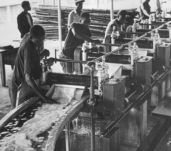
Ribbed smoked sheets are produced by passing coagulated latex through a series of rollers to produce thin sheets, which are embossed with a ribbed pattern. The ribbed pattern serves mainly to increase the surface area of the material and aid its drying. The sheets are preserved by placing them in a smokehouse at 60ºC for a week, visually graded, sorted and packed in bales.
Compounding formulas used for natural rubbers are essentially the same as those used for most of the unsaturated synthetic rubbers. Accelerators, activators, antioxidants, fillers, softeners and vulcanizing agents may all be required, depending upon what properties are desired in the finished compound.
The hazards arising from the use of mechanized production methods (i.e., rolls and centrifuges) require strict safety controls during installation, use and maintenance, including attention to machine guarding. Appropriate precautions must be used when processing chemicals are used. Attention should be paid to the use of appropriate walking and working surfaces to prevent slips, trips and falls. Employees should receive training in safe work practices. Strict supervision is required to prevent accidents associated with the use of heat as an aid in curing.
Tyre Manufacturing
Manufacturing Process
Figure 1 shows an overview of the tyre manufacturing process.
Figure 1. The tyre manufacturing process

Compounding and Banbury mixing
A Banbury mixer combines rubber stock, carbon black and other chemical ingredients to create a homogeneous rubber material. Time, heat and raw materials are factors utilized to engineer material composition. The ingredients are generally provided to the plant in pre-weighed packages or are prepared and weighed by the Banbury operator from bulk quantities. Measured ingredients are placed onto a conveyor system, and the Banbury is charged to initiate the mixing process.
Hundreds of components are combined to form rubber utilized for tyre manufacturing. The components include compounds which act as accelerators, anti-oxidants, anti-ozonants, extenders, vulcanizers, pigments, plasticizers, reinforcing agents and resins. Most constituents are unregulated and may not have had extensive toxicological evaluations. Generally speaking, the Banbury operators’ occupational exposures to the raw materials have been reduced by improvements in administrative and engineering controls. However, concern remains due to the nature and quantity of components which make up the exposure.
Milling
Shaping of rubber begins in the milling process. At the completion of the Banbury mixing cycle, rubber is placed onto a drop mill. The milling process shapes the rubber into flat, long strips by forcing it through two set rolls rotating in different directions at different speeds.
Mill operators are generally concerned with safety hazards associated with the open operation of the turning rolls. Older mills usually had trip wires or bars which could be pulled by the operator if he or she got caught in the mill (see figure 2); modern mills have body bars at about knee level that are automatically triggered if the operator is caught in the mills (see figure 3).
Figure 2. Older mill with a trip bar located too high to be effective. The operator, however, has large gloves which would be pulled into the mill before his fingers.
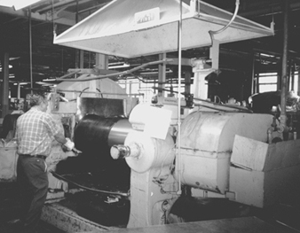
Ray C. Woodcock
Figure 3. Mill for calender line with a body bar guard that shuts down the mill if tripped by workers.
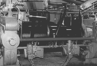
James S. Frederick
Most facilities have extensive emergency rescue procedures in place for workers trapped in mills. Mill operators are exposed to heat and noise as well as components formed by the heating of, or released from, rubber) (see a canopy hood over a drop mill in figure 4).
Figure 4. Drop mill and dryer with canopy hood and trip wires
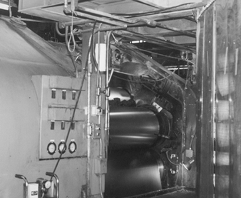
James S. Frederick
Extruding and calendering
The calender operation continues to shape rubber. The calender machine consists of one or more (often four) rolls, through which the rubber sheets are forced (see figure 3).
The calender machine has the following functions:
- to prepare compounded rubber as a uniform sheet of definite thickness and width
- to place a thin coat of rubber on a fabric (“coating” or “skimming”)
- to force rubber into the interstices of fabric by friction (“frictioning”).
The rubber sheets coming off the calender are wound on drums, called “shells,” with fabric spacers, called “liners,” to prevent sticking.
The extruder is often referred to as a “tuber” because it creates tube-like rubber components. The extruder functions by forcing rubber through dies of appropriate shape. The extruder consists of a screw, barrel or cylinder, head and die. A core or spider is used to form the hollow inside of tubing. The extruder makes the large, flat section of tyre treads.
Extruder and calender operators may be exposed to talc and solvents, which are used in the process. Also, the workers at the end of the extrusion operation are exposed to a highly repetitive task of placing the tread onto multi-tiered carts. This operation is often referred to as booking treads, because the cart looks like a book with the trays being the pages. The configuration of the extruder as well as the weight and quantities of tread to be booked contribute to the ergonomic impact of this operation. Numerous changes have been made to lessen this, and some operations have been automated.
Component assembly and building
Tyre assembly can be a highly automated process. The tyre assembly machine consists of a rotating drum, on which the components are assembled, and feeding devices to supply the tyre builder with the components to assemble (see figure 5). The components of a tyre include beads, plies, side walls and treads. After the components are assembled, the tyre is often referred to as a “green tyre”.
Figure 5. Operator assembling a tyre on a single-stage tyre machine
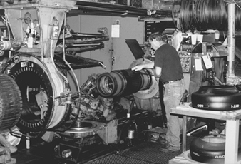
Tyre builders and other workers in this area of the process are exposed to a number of repetitive motion operations. Components, often in heavy rolls, are placed onto the feeding portions of the assembly equipment. This may entail extensive lifting and handling of heavy rolls in a limited space. The nature of assembly also requires the tyre builder to perform a series of similar or identical motions on each assembly. Tyre builders utilize solvents, such as hexane, which allow the tread and plies of rubber to adhere. Exposure to the solvents is an area of concern.
After being assembled, the green tyre is sprayed with a solvent- or water-based material to keep it from adhering to the curing mould. These solvents potentially expose the spray operator, material handler and curing press operator. Nowadays, water-based materials are mostly used.
Curing and Vulcanizing
Curing press operators place green tyres into the curing press or onto press loading equipment. Curing presses in operation in North America exist in a variety of types, ages and degrees of automation (see figure 6). The press utilizes steam to heat or cure the green tyre. Rubber curing or vulcanization transforms the tacky and pliable material to a non-tacky, less pliable, long-lasting state.
Figure 6. Passenger and light truck Bag-o-matic McNeal curing press ventilated with a ceiling fan, Akron, Ohio, US
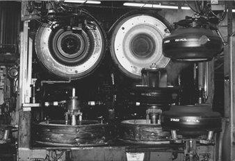
James S. Frederick
When rubber is heated in curing or in earlier stages of the process, carcinogenic N-nitrosamines are formed. Any level of N-nitrosamine exposure should be controlled. Attempts should be made to limit N-nitrosamine exposure as much as feasible. In addition, dusts, gases, vapours and fumes contaminate the work environment when rubber is heated, cured or vulcanized.
Inspection and finishing
Following curing, finishing operations and inspection remain to be performed before the tyre is stored or shipped. The finishing operation trims flash or excess rubber from the tyre. This excess rubber remains on the tyre from vents in the curing mould. Additionally, excess layers of rubber may need to be ground from the side walls or raised lettering on the tyre.
One of the major health hazards that workers are exposed to while handling a cured tyre is repetitive motion. The tyre finishing or grinding operations typically expose workers to cured rubber dust or particulate (see figure 7). This contributes to respiratory illness in workers in the finishing area. In addition, a potential exists for solvent exposure from the protective paint which is often used to protect the side-wall or tyre lettering.
Figure 7. A dust collector of a grinding wheel captures rubber dust
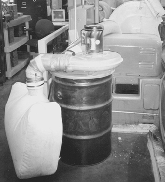
Ray C. Woodcock
After finishing, the tyre is ready to be stored in a warehouse or shipped from the plant.
Health and Safety Concerns
Occupational health and safety concerns in tyre manufacturing facilities have always been and continue to be of the utmost importance. Often the impact of serious workplace injuries overshadows the devastation associated with illnesses which may be linked to workplace exposures. Due to extended latency periods, some diseases do not become apparent until after the worker has left the job. Also, many diseases which may be associated with tyre plant occupational exposures are never diagnosed as being occupation-related. But diseases such as cancer continue to be prevalent among rubber workers in tyre manufacturing facilities.
Many scientific studies have been performed on workers in tyre manufacturing facilities. Some of these studies have identified excess mortality from bladder, stomach, lung, haematopoietic and other cancers. These excess deaths often cannot be attributed to a specific chemical. This is in part due to workplace exposures involving many individual chemicals throughout the duration of exposure and/or combination exposures to several chemicals simultaneously. Also frequent changes occur to the formulation of materials used in a tyre plant. These changes in types and quantities of the rubber compound constituents create additional difficulty in tracking the causal agents.
Another area of concern is respiratory problems or respiratory irritation in tyre plant workers (i.e., chest tightness, shortness of breath, reduction in pulmonary functions and other respiratory symptoms). Emphysema has been shown to be a common reason for early retirement. These problems are often found in curing, processing (premixing, weighing, mixing and heating of raw ingredients) and final finishing (inspection) areas of the plants. In processing and curing, chemical exposures are often to numerous constituents at relatively low exposure levels. Many of the individual components to which workers are exposed are not regulated by governmental agencies. Almost as many have not been adequately tested for toxicity or carcinogenicity. Also, in the United States, tyre plant workers in these areas are not likely to be required to utilize respiratory protection. No clear cause of respiratory distress has been identified.
Many workers in tyre plants have suffered from contact dermatitis, which has often not been linked to one substance in particular. Some of the chemicals which have been linked to dermatitis are no longer used in the manufacture of tyres in North America; however, many of the replacement chemicals have not been fully evaluated.
Repetitive or cumulative trauma disorders have been identified as an area of concern in tyre manufacturing. Repetitive trauma disorders include tenosynovitis, carpal tunnel syndrome, synovitis, noise-induced hearing loss and other conditions resulting from repetitive motion, vibration or pressure. The tyre manufacturing process inherently contains excessive and multiple occurrences of material and product manipulation for a large portion of production workers. In some countries, many improvements have been and continue to be introduced at the plants to address this issue. Many of the innovative improvements have been initiated by workers or joint labour-management committees. Some of the improvements provide engineering controls to manipulate materials and product (see figure 8).
Figure 8. A vacuum lift carries bags to the charging conveyor for a Banbury mixer, eliminating back strain from manual handling

Ray C. Woodcock
Due in part to workforce restructuring, the average age of workers in many tyre plants continues to increase. Also, more and more tyre manufacturing facilities tend to operate continuously. Many facilities with continuous operations include work shift schedules of 12-hour and/or rotating shifts. Research continues to study the possible relationships between extended work shifts, age and cumulative trauma disorders in tyre manufacturing.
" DISCLAIMER: The ILO does not take responsibility for content presented on this web portal that is presented in any language other than English, which is the language used for the initial production and peer-review of original content. Certain statistics have not been updated since the production of the 4th edition of the Encyclopaedia (1998)."