- You are here:
-
Home

-
Contents
-
Part XII. Chemical Industries
-
Chemical Processing
- Examples of Chemical Processing Operations
Glass, Ceramics and Related Materials
This chapter covers the following product sectors:
- glass
- synthetic vitreous fibres
- pottery
- ceramic tile
- industrial ceramics
- brick and tile
- refractories
- synthetic gems
- optical fibres.
Interestingly, not only do most of these sectors have roots in antiquity, but they also share a number of common general processes. For example, all are fundamentally based on the use of naturally occurring raw materials in powder or fine particulate form which are transformed by heat into the desired products. Therefore, despite the range of processes and products encompassed in this group, these common processes allow a common overview of potential health hazards associated with these industries. Since the various manufacturing sectors are composed of both small, fragmented segments (e.g., brick manufacturing) and large, technically sophisticated manufacturing plants employing thousands of workers, each sector is described separately.
Common Processes and Hazards
There are common safety and health hazards encountered in manufacturing of products in these business sectors. The hazards and control measures are discussed in other sections of the Encyclopaedia. Process-specific hazards are discussed in the individual sections of this chapter.
Batch raw material processes
Most of the industrial manufacturing processes receive dry solid raw materials in bulk form or individual bags. Bulk solid raw materials are unloaded from hopper rail cars or over-the-road trucks into bins, hoppers or mixers by gravity, pneumatic transfer lines, screw conveyors, bucket conveyors or other mechanical transfer. Pallets of bagged raw materials (20 to 50 kg) or large bulk fabric bag containers (0.5 to 1.0 tonnes) are unloaded from truck trailers or rail boxcars by powered industrial lift trucks, cranes or hoists. Individual bags or raw materials are removed from pallets manually or with powered lift assists. Bagged raw materials are typically charged into a bag dumping station or directly into storage hoppers or scale hoppers.
Potential safety and health hazards associated with the solid raw material unloading, handling and transfer processes include:
- noise exposures in the 85 to 100 dBA range. Pneumatic vibrators, compressors, valve actuators, mixing drive motors, blowers, and dust collectors are some major noise sources.
- exposures to respirable airborne particulate from the transfer and mixing of granular solid raw materials. Exposures depend on composition of raw materials but may commonly include silica (SiO2), clay, alumina, limestone, alkaline dusts, metal oxides, heavy metals and nuisance particulate.
- ergonomic hazards associated with manual lifting or handling of raw material bags, vibrators, or transfer lines and system maintenance activities
- physical hazards from manoeuvring rail cars or trucks, powered-industrial truck traffic, work at elevated heights, confined-space entries and contact with electrical, pneumatic or mechanical energy sources—e.g., nip points, rotating parts, drive gears, shafts, belts and pulleys.
Firing or melting processes
Manufacturing products in these business sectors involves drying, melting or firing processes in kilns or furnaces. The heat for these processes is generated by combustion of propane, natural gas (methane) or fuel oil, electric arc melting, microwave, dielectric drying and/or resistance heating with electricity. Potential hazards presented from firing or melting processes include:
- exposures to combustion products such as carbon monoxide, nitrogen oxides (NOx) and sulphur dioxide
- fumes and particulates from airborne raw materials (e.g., silica, metals, alkaline dusts) or by-products (e.g., hydrogen fluoride, cristobalite, heavy metal fumes)
- fire or explosion associated with fuel systems used for process heat or fuel for lift trucks; potential fire or explosion hazards associated with flammable fuel storage tanks, piping distribution systems and vaporizers. Back-up or stand-by fuel systems in-frequently used for natural gas curtailments can present similar fire or explosion concerns.
- infrared radiation exposure from molten material, which can increase risk of heat cataracts or skin burns
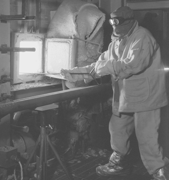
- radiant energy and heat stress. The working environment around furnaces or kilns can be extremely hot. Significant heat stress problems can occur when emergency repair work or routine maintenance is performed near or above firing or melting processes. Severe thermal burns can result from direct skin contact with hot surfaces or molten materials (see figure 1).
Figure 1. Quality-control technician
- electrical energy hazards. Direct contact with high-voltage electric energy used for resistance heating to supplement fuel-fired processes presents an electrocution hazard and possible health concerns about exposure to electromagnetic fields (EMF). Strong magnetic and electric fields can potentially interfere with pacemakers and other implanted medical devices.
- noise exposures above 85 to 90 dBA from combustion blowers, batch hoppers or mixers, feed processes and conveyors.
handling in production, fabrication, packaging and warehousing
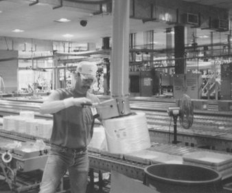
Material-handling, fabrication and packaging processes differ to a large extent in this business sector, as do the size, shape and weights of products. The high density of materials in this sector or bulky configurations present common material-handling hazards. Manual lifting and material handling in production, fabrication, packaging and warehousing in this industry accounts for many disabling injuries. (See “Injury and illness profile” section below.) Injury reduction efforts are focusing on reducing manual lifting and material handling. For example, innovative packaging designs, robotics for stacking and palletizing finished products, and automatic guided transport vehicles for warehousing are starting to be used in select parts of this business sector to eliminate manual material handling and associated injuries. Use of conveyors, manned lift assists (e.g., vacuum hoists) and scissors platforms for handling and palletizing products are currently common material-handling practices (see figure 2).
Figure 2. Vacuum lift assist being used
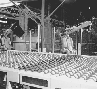
The use of robotics to eliminate manual material handling is playing a major role in prevention of ergonomic injuries. Robotics has reduced ergonomic stresses and severe laceration injuries that have been historically associated with material handling (e.g., flat glass) in the production workforce (see figure 3). However, increased utilization of robotics and process automation introduces moving machinery and electric power hazards, which transforms the types of hazards and also transfers risks to other workers (from production to maintenance workers). Proper designs of electronic controls and logic sequencing, machine guards, total energy lockout practices and establishing safe operating and maintenance procedures are fundamental ways to control injuries to maintenance and production workers.
Figure 3. Robotics used in plate-glass
Rebuilds and reconstruction activities
Numerous potential health and safety hazards are encountered during periodic major rebuilds or cold repairs to furnaces or kilns. A wide range of hazards associated with construction activities may be encountered. Examples include: ergonomic hazards with material handling (e.g., refractory bricks); airborne exposures to silica, asbestos, refractory ceramic fibres or particulate matter containing heavy metal, during demolition, or by-products of cutting and welding; heat stress; work at elevated heights; slip, trip or fall hazards; confined-space hazards (see figure 4); and contact with hazardous energy sources.
Figure 4. Confined-space entry

Glass
General profile
Glass was formed naturally from common elements in the earth’s crust long before anyone ever thought of experimenting with its composition, moulding its shape or putting it to the myriad of uses that it enjoys today. Obsidian, for instance, is a naturally occurring combination of oxides fused by intense volcanic heat and vitrified (made into a glass) by rapid air cooling. Its opaque, black colour comes from the relatively high amounts of iron oxide it contains. Its chemical durability and hardness compare favourably with many commercial glasses.
Glass technology has evolved for 6,000 years, and some modern principles date back to ancient times. The origin of the first synthetic glasses is lost in antiquity and legend. Faience was made by the Egyptians, who molded figurines from sand (SiO2), the most popular glass-forming oxide. It was coated with natron, the residue left by the flooding Nile river, which was composed principally of calcium carbonate (CaCO3), soda ash (Na2CO3), salt (NaCl) and copper oxide (CuO). Heating below 1,000 °C produced a glassy coating by the diffusion of the fluxes, CaO and Na2O into the sand and their subsequent solid-state reaction with the sand. The copper oxide gave the article an appealing blue colour.
According to the definition given by Morey: “Glass is an inorganic substance in a condition which is continuous with, and analogous to, the liquid state of that substance, but which, as the result of a reversible change in viscosity during cooling, has attained so high a degree of viscosity as to be, for all practical purposes, rigid.” ASTM defines glass as “an inorganic product of fusion that has cooled to a rigid condition without crystallizing.” Both organic and inorganic materials may form glasses if their structure is non-crystalline—that is, if they lack long-range order.
A most important development in glass technology was the use of a blow pipe (see figure 5), which was first used in approximately 100 years BC. From then onwards, there was a rapid development in the technique of manufacturing glass.
Figure 5. The blow pipe

The first glass was coloured because of the presence of various impurities such as oxides of iron and chromium. Virtually colourless glass was first made some 1,500 years ago.
At that time glass manufacturing was developing in Rome, and from there it moved to many other countries in Europe. Many glass works were built in Venice, and an important development took place there. In the 13th century, many of the glass plants were moved from Venice to a nearby island, Murano. Murano is still a centre for the production of hand-made glass in Italy.
By the 16th century, glass was made all over Europe. Now Bohemian glass from the Czech Republic is well known for its beauty and glass plants in the United Kingdom and Ireland produce high-quality lead crystal glass tableware. Sweden is another country that is home to artistic glass crystalware production.
In North America the first manufacturing establishment of any sort was a glass factory. English settlers started to produce glass at the beginning of the 17th century at Jamestown, Virginia.
Today glass is manufactured in most countries all over the world. Many products of glass are made in fully automatic processing lines. Although glass is one of the oldest materials, its properties are unique and not yet fully understood.
The glass industry today is made up of several major market segments, which include the flat glass market, the consumer houseware market, the glass containers market, the optical glass industry and the scientific glassware market segment. The optical and scientific glass markets tend to be very ordered and are dominated by one or two suppliers in most countries. These markets are also much lower in volume than the consumer-based markets. Each of these markets has developed over the years by innovations in specific glass technology or manufacturing advancements. The container industry, for example, was driven by the development of high-speed bottle-making machines developed in the early 1900s. The flat glass industry was significantly advanced by the development of the float glass process in the early 1960s. Both of these segments are multi-billion-dollar businesses worldwide today.
Glass housewares fall into four general categories:
- tableware (including dinnerware, cups and mugs)
- drinkware
- bakeware (or ovenware)
- top-of-stove cookware.
While worldwide estimates are difficult to obtain, the market for glass housewares is undoubtedly on the order of US$1 billion in the United States alone. Depending upon the specific category, a variety of other materials compete for market share, including ceramics, metals and plastics.
Manufacturing processes
Glass is an inorganic product of fusion which has cooled to a rigid condition without crystallizing. Glass is typically hard and brittle and has a conchoidal fracture. Glass may be manufactured to be coloured, translucent or opaque by varying the dissolved amorphous or crystalline materials that are present.
When glass is cooled from the hot molten state, it gradually increases in viscosity without crystallization over a wide temperature range, until it assumes its characteristic hard, brittle form. Cooling is controlled to prevent crystallization, or high strain.
While any compound which has these physical properties is theoretically a glass, most commercial glasses fall into three main types and have a wide range of chemical compositions.
- Soda-lime-silica glasses are the most important glasses in terms of quantity produced and variety of use, including almost all flat glass, containers, low-cost mass-produced domestic glassware and electric light bulbs.
- Lead-potash-silica glasses contain a varying but often high proportion of lead oxide. Optical glass manufacture makes use of the high refractive index of this type of glass; hand-blown domestic and decorative glassware makes use of its ease of cutting and polishing; electrical and electronic applications takes advantage of its high electrical resistivity and radiation protection.
- Borosilicate glasses have a low thermal expansion and are resistant to thermal shock, which makes them ideal for domestic oven and laboratory glassware and for glass fibre for plastic reinforcements.
A commercial glass batch consists of a mixture of several ingredients. However, the largest fraction of the batch is made up of from 4 to 6 ingredients, chosen from such materials as sand, limestone, dolomite, soda ash, borax, boric acid, feldspathic materials, lead and barium compounds. The remainder of the batch consists of several additional ingredients, chosen from a group of some 15 to 20 materials commonly referred to as minor ingredients. These latter additions are added with a view to providing some specific function or quality, such as colour, which is to be realized during the glass preparation process.
Figure 6 illustrates the basic principles of glass manufacture. The raw materials are weighed, mixed and, after the addition of broken glass (cullet), taken to the furnace for melting. Small pots of up to 2 tonnes capacity are still used for the melting of glass for hand-blown crystalware and special glasses required in small quantity. Several pots are heated together in a combustion chamber.
Figure 6. The processes & materials involved

In most modern manufacture, melting takes place in large regenerative, recuperative or electric furnaces built of refractory material and heated by oil, natural gas or electricity. Electric boosting and cold top electric melting were commercialized and became extensively utilized globally in the late 1960s and 1970s. The driving force behind cold top electric melting was emission control, while electric boosting was generally used in order to improve glass quality and to increase throughput.
The most significant economic factors concerning the use of electricity for glass furnace melting are related to fossil fuel costs, the availability of various fuels, electricity costs, capital costs for equipment and so on. However, in many instances the prime reason for the use of electric melting or boosting is environmental control. Various locations worldwide either already have or are expected soon to have environmental regulations that strictly restrict the discharge of various oxides or particulate matter in general. Thus, manufacturers in many locations face the possibility of either having to reduce glass melting throughputs, install baghouses or precipitators in order to handle waste flue gases or modify the melting process and include electric melting or boost. The alternatives to such modification may in some cases be plant shutdowns.
The hottest part of the furnace (superstructure) may be at 1,600 to 2,800°C. Controlled cooling reduces the glass temperature to 1,000 to 1,200°C at the point where the glass leaves the furnace. In addition, all types of glass are subjected to further controlled cooling (annealing) in a special oven or lehr. Subsequent processing will depend on the type of manufacturing process.
Automatic blowing is used on machines for bottle and lamp bulb production in addition to traditional hand-blown glass. Simple shapes, such as in insulators, glass bricks, lens blanks and so on, are pressed rather than blown. Some manufacturing processes use a combination of mechanical blowing and pressing. Wired and figured glass is rolled. Sheet glass is drawn from the furnace by a vertical process which gives it a fire-finished surface. Owing to the combined effects of drawing and gravity, some minor distortion is inevitable.
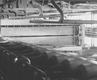
Plate glass passes through water-cooled rollers onto an annealing lehr. It is free from distortion. Surface damage can be removed by grinding and polishing after fabrication. This process has largely been replaced by the float glass process, which was introduced in recent years (see figure 7). The float process has made possible the manufacture of a glass that combines the advantages of both sheet and plate. Float glass has a fire-finished surface and is free from distortion.
Figure 7. Continuous float process
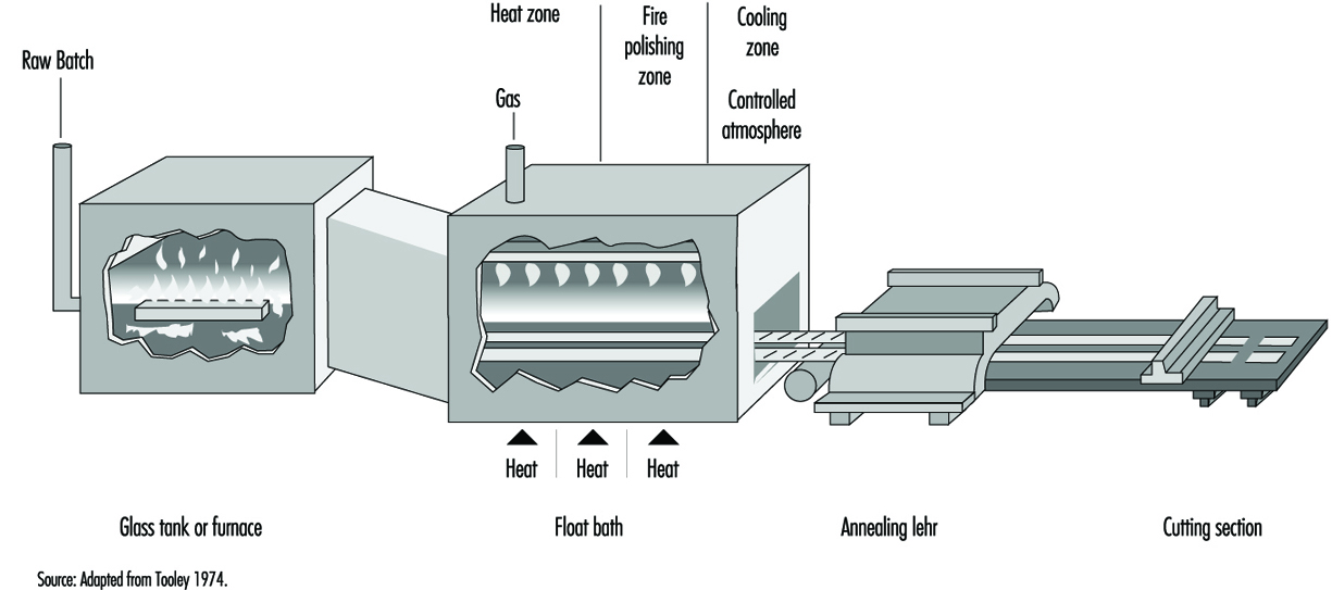
In the float process, a continuous ribbon of glass moves out of a melting furnace and floats along the surface of a bath of molten tin. The glass conforms to the perfect surface of the molten tin. On its passage over the tin, the temperature is reduced until the glass is sufficiently hard to be fed onto the rollers of the annealing lehr without marking its under surface. An inert atmosphere in the bath prevents oxidation of the tin. The glass, after annealing, requires no further treatment and can be further processed by automatic cutting and packing (see figure 8).
Figure 8. Ribbon of float glass exiting from lehr
The trend in new residential and commercial architecture toward the inclusion of more glazing area, and the need to reduce energy consumption, has put increased emphasis on improving the energy efficiency of windows. Thin films deposited at the surface of the glass provide low emissivity or solar control properties. The commercialization of such commodity-coated products requires a low cost, large area deposition technology. As a result, an increasing number of float glass manufacturing lines are equipped with sophisticated on-line coating processes.
In commonly used chemical vapour deposition (CVD) processes, a complex gas mixture is brought into contact with the hot substrate, where it pyrolytically reacts to form a coating at the surface of the glass. In general, the coating equipment consists of thermally controlled structures which are suspended over the width of the glass ribbon. They may be located in the tin bath, the lehr gap or the lehr. The function of the coaters is to uniformly deliver the precursor gases over the ribbon width in a temperature-controlled fashion and to safely extract the exhaust gas by-products from the deposition region. For multiple coating stacks, multiple coaters are used in series along the glass ribbon.
For the treatment of the exhaust gas by-products generated by such large-scale processes, wet scrubbing techniques with a conventional filter press are normally sufficient. When the effluent gases are not easily reacted or wetted by aqueous solutions, incineration is the primary option.
Some optical glasses are chemically strengthened by processes which involve immersing the glass for several hours in high-temperature baths containing molten salts of, typically, lithium nitrate and potassium nitrate.
Safety glass is of two major types:
- Toughened glass is made by pre-stressing by heating and then rapidly cooling pieces of flat glass of desired shape and size in special ovens.
- Laminated glass is formed by bonding a sheet of plastic (usually polyvinyl butyral) between two thin sheets of flat glass.
Synthetic Vitreous Fibres
General profile
Synthetic vitreous fibres are produced from a wide variety of materials. They are amorphous silicates manufactured from glass, rock, slag or other minerals. The fibres produced are both continuous and discontinuous fibres. In general, the continuous fibres are glass fibres drawn through nozzles and used to reinforce other materials, such as plastics, to produce composite materials with unique properties. The discontinuous fibres (generally known as wools) are used for many purposes, most commonly for thermal and acoustical insulation. Synthetic vitreous fibres, for purposes of this discussion, have been divided into continuous glass fibres, with the insulation wools made of glass, rock or slag fibres, and refractory ceramic fibres, which are generally aluminium silicates.
The possibility of drawing heat-softened glass into fine fibres was known to glass makers in antiquity and is actually older than the technique of glass blowing. Many early Egyptian vessels were made by winding coarse glass fibres onto a suitably shaped mandrel of clay, then heating the assembly until the glass fibres flowed into one another and, after cooling, removing the clay core. Even after the advent of glass blowing in the 1st century AD, the glass fibre technique was still employed. Venetian glassmakers in the 16th and 17th centuries used it for decorating glassware. In this case, bundles of opaque white fibres were wound onto the surface of a plain transparent blown glass vessel (e.g., a goblet) and then fused into it by heating.
Despite the long history of generally decorative or artistic uses of glass fibres, widespread use did not arise again until the 20th century. Initial commercial US production of glass fibres occurred in the 1930s, while in Europe the initial use occurred some years earlier. Rock and slag wools were produced several years earlier than that.
The manufacture and use of synthetic vitreous fibres is a global multi-billion-dollar industry since these useful materials have become an important component of modern society. Their uses as insulations have resulted in tremendous reduction in energy requirements for heating and cooling buildings, and this energy savings has resulted in significant reduction in global pollution associated with energy production. The number of applications of continuous glass filaments as reinforcements for a plethora of products, from sporting goods to computer chips to aerospace applications, has been estimated to be in excess of 30,000. The development and widespread commercialization of refractory ceramic fibres occurred in the 1970s, and these fibres continue to play an important role in protecting workers and equipment in a variety of high-temperature manufacturing processes.
Manufacturing processes
Continuous glass filaments
Glass filaments are formed by drawing the molten glass through precious-metal bushings into fine filaments of nearly uniform diameter. Due to the physical requirements for the fibres when used as reinforcements, their diameters are relatively large compared to those in the insulation wools. Almost all continuous glass filaments have diameters of 5 to 15 μm or greater. These large diameters, coupled with the narrow range of diameters produced during the manufacture, eliminate any potential chronic respiratory effects, as the fibres are too large to be inhaled into the lower respiratory tract.
Continuous glass fibres are made by the rapid attenuation of drops of molten glass exuding through nozzles under gravity and suspended from them. The dynamic balance between the forces of surface tension and mechanical attenuation results in the drop of glass taking on the shape of a meniscus held at the annular opening of the nozzle and tapering to the diameter of the fibre being drawn. For fibre drawing to be successful, the glass has to be within a narrow range of viscosities (i.e., between 500 and 1,000 poise). At lower viscosities, the glass is too fluid and falls away from the nozzles as drops; in this case surface tension dominates. At higher viscosities, the tension in the fibre during attenuation is too high. The rate of flow of glass through the nozzle can also become too low to maintain a meniscus.
The function of the bushing is to provide a plate containing several hundred nozzles at a uniform temperature and to condition the glass to this uniform temperature so that the fibres drawn are of uniform diameter. Figure 9 shows a schematic diagram of the principal features of a direct-melt bushing attached to a forehearth from which it takes a supply of molten glass very near the temperature at which the glass will pass through the nozzles; in this case, therefore, the basic function of the bushing is also its sole function.
Figure 9. Schematic of direct-melt bushing

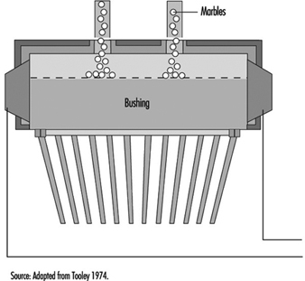
In the case of a bushing operating from marbles, a second function is required—namely, to first melt the marbles before conditioning the glass to the correct fibre-drawing temperature. A typical marble bushing is shown in figure 10. The broken line within the bushing is a perforated plate which retains the unmelted marbles.
Figure 10. Schematic of a marble bushing
The design of bushings is largely empirical. For reasons of resistance to attack by molten glass and stability at the temperatures needed for fibre drawing, bushings are made from platinum alloys; both 10% rhodium-platinum and 20% rhodium-platinum are used, the latter being more resistant to distortion at elevated temperatures.
Before the individual fibres being drawn from a bushing are gathered and consolidated into a strand, or a multiplicity of strands, they are coated with a fibre size. These fibre sizes are basically of two types:
- starch-oil sizes usually applied to fibres intended for weaving into fine fabrics or similar operations
- keying agent plus film-former sizes applied to fibres intended for the direct reinforcement of plastics and rubber.
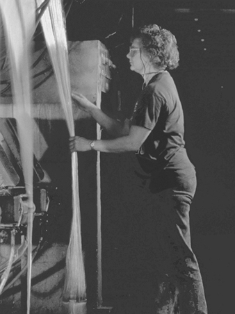
After the fibre is formed, a protective coating of organic sizing is applied at an applicator and the continuous filaments are gathered into a multifilament strand (see figure 11) before being wrapped on a winding tube. Applicators function by allowing the fan of fibres, when about 25 to 45 mm wide and on their way to the gathering shoe below the applicator, to pass over a moving surface covered with a film of fibre size.
Figure 11. Textile glass filaments
There are basically two types of applications:
- roller applicators, made of rubber, ceramic or graphite, in which the fibre runs over the surface of the roller coated with a film of fibre size
- belt applicators, in which at one end the belt passes over a driven roller which dips the belt into the fibre size and at the other end passes over a fixed hard chrome steel bar at which position the fibres touch the belt to pick up the size.
The protective coating and the fibre-gathering process can vary depending on the types of textile or reinforcement fibre being produced. The basic objective is to coat the fibres with size, gather them into a strand and locate them on a removable tube on the collet with the minimum necessary tension.
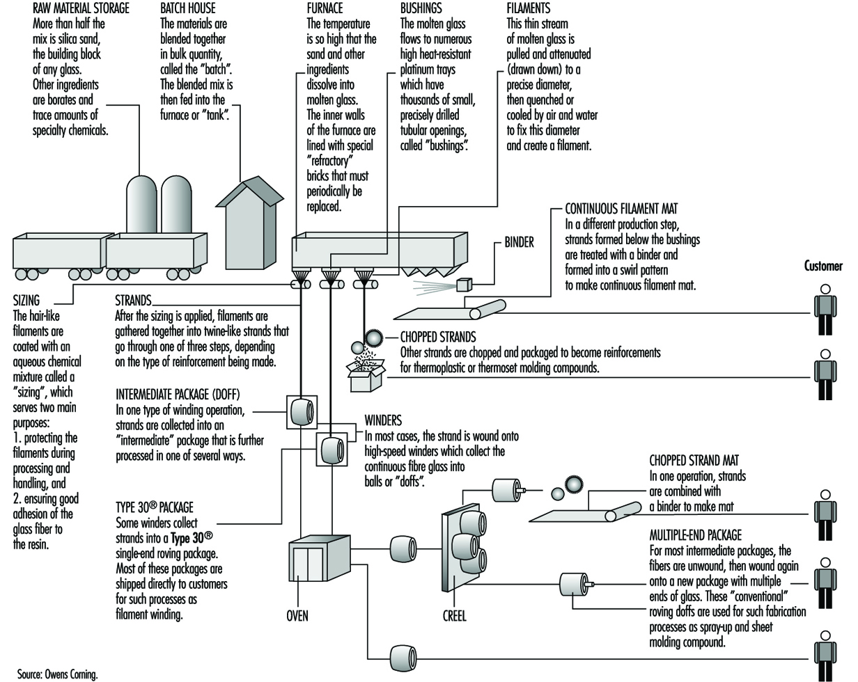
Figure 12 shows the process of continuous glass manufacturing.
Figure 12. Continuous filament glass manufacturing
Insulation wool manufacturing
In contrast to continuous filaments, the fibres of the insulation wools and refractory ceramic fibres are made in very high energy processes in which molten material is dropped into either spinning discs or a series of rotating wheels. These methods result in the production of fibres with a range of diameters much wider than seen with continuous filaments. Thus, all of the insulation wools and ceramic fibres contain a fraction of the fibres with diameters of less than 3.0 μm; these could become respirable if fractured into relatively short lengths (less than 200 to 250 μm). Extensive data are available on exposures to respirable synthetic vitreous fibres in the workplace.
Several processes are used to manufacture glass wool, including the steam blowing process and flame blown process; but the most popular is the rotary forming process developed in the mid-1950s. The rotary processes have largely replaced direct blowing processes for the commercial production of glass-fibre insulation products. These rotary processes all employ a hollow drum, or spinner, mounted with its axis vertical. The vertical wall of the spinner is perforated with several thousand holes uniformly distributed around the circumference. Molten glass is allowed to fall at a controlled rate into the centre of the spinner, from where some suitable distributor forces it to the inside of the vertical perforated wall. From that position, centrifugal force drives the glass radially outwards in the form of discrete glass filaments issuing from every perforation. Further attenuation of these primary filaments is achieved by a suitable blowing fluid emerging from a nozzle or nozzles arranged around and concentric with the spinner. The net result is the production of fibres with a mean fibre diameter of 6 to 7 mm. The blowing fluid acts in a downwards direction and so, as well as providing the final attenuation, it also deflects the fibres towards a collecting surface situated below the spinner. On the way to this collecting surface, the fibres are sprayed with a suitable binder before being uniformly distributed across the collecting surface (see figure 13).
Figure 13. The rotary process for making glass wool

In a rotary process, glass wool fibres are made by allowing molten glass to run through a series of small openings which are situated in a revolving spinner and then attenuating the primary filament by air or steam blowing.
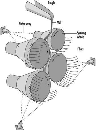
Mineral wool, however, cannot be produced on the rotary spinner process and historically has been produced in process with a series of horizontal spinning mandrels. The mineral wool process consists of a set of rotors (mandrels) mounted in a cascade formation and rotating very rapidly (see figure 14). A stream of molten stone is continuously transferred to one of the upper rotors and from this rotor distributed on the second and so on. The melt is uniformly spread on the outside surface of all the rotors. From the rotors, droplets are thrown out by centrifugal force. The droplets are attached to the rotor surface by elongated necks which, under further elongation and simultaneous cooling, develop into fibres. The elongation is, of course, followed by a decrease in diameter which, in turn, causes an accelerated cooling. Thus, there is a lower limit for the diameter among fibres produced in this process. A normal distribution of fibre diameters around the mean value is, therefore, not expected.
Figure 14. Mineral wool process (rock & slag)
Refractory ceramic fibres
Ceramic fibres are primarily produced by blowing and spinning with methods similar to those described for the insulation wools. In the steam blowing process, raw materials such as alumina and silica are fused in an electric furnace, and the molten material is drawn off and blown with either pressurized steam or other hot gas. The fibres produced are then collected on a screen.
Similar to the spinning process for rock and slag fibres, those for ceramic fibres produce a high proportion of long silky fibres. In this method, a stream of molten material is dropped onto rapidly spinning discs and thrown off tangentially to form fibres.
Pottery Industry
General profile
The making of pottery is one of the oldest of human crafts. Over the centuries different styles and techniques have developed in different parts of the world. In the 18th century, a flourishing industry in many parts of Europe was strongly influenced by the import of fine and highly decorated ware from the Far East. Japan had learned the ceramic art from China about 400 years earlier. With the Industrial Revolution and the general change in conditions in Western Europe, production grew rapidly. At present, almost every country manufactures some ware for domestic use, and pottery is an important export from some countries. Production is now on a factory scale in many parts of the world. While the basic principles of manufacture have not changed, there has been considerable progress in the way in which manufacturing is carried out. This is particularly so in the forming or shaping of ware, in its firing and in the decoration techniques used. The increasing use of microprocessors and robots results in the introduction of high levels of automation in production areas. However, there also still exist everywhere many small-scale craft potteries.
Methods of forming
The earliest method of making pottery involved the hand method of building. Coils of clay are wound around, one on top of the other, and stuck together by pressing with the hands. The clay is first made into a soft state by working it with water. The object is then shaped and moulded by hand, once the coils are adhered.
The potter’s wheel has become a tool for creating pottery. With this method of forming, a pile of clay is placed on a revolving circular plate and is shaped by the wet hands of the potter. The water keeps the potter’s hands from sticking to the clay and keeps the clay moist and workable. Handles, spouts and other protrusions from the spinning clay are placed on just before the object is fired.
Casting is often used today when pottery of a high quality is desired and when the walls of the vessel are to be very thin. A mixture of clay and water, called slip, is poured into a plaster-of-Paris mould. The plaster absorbs the water, causing a thin coat of clay to be deposited all around the inside of the mould. When the deposit of clay is thick enough to form the walls of the vase, the rest of the slip is poured out, leaving the wet piece of ware on the inside of the form. As this dries it shrinks somewhat and can be removed from the mould. Usually the moulds are so constructed that they can be taken apart.
When the piece becomes thoroughly dry, it is smoothed and prepared for the firing process. It is placed in a fire-clay box called a sagger, which protects the piece from the flames and gases that are emitted during the process, just as an oven would protect a loaf of bread that is being baked. The saggers are placed one on top of another in a kiln. The kiln is a large structure that is built of fire brick and is surrounded by flues so that the flames of the fire may totally surround the dishes yet never actually come in contact with them. Smoke would discolour the pieces if they were not protected in such a manner.
Most pieces are fired at least twice. The first time through the kiln is called the bisque firing, and the piece of pottery is called a biscuit or bisque piece. After firing, the biscuit ware is glazed. A glaze is a glassy, glossy coating that makes the pottery more attractive and serviceable. Glazes contain silica, a flux to lower the melting temperature (lead, barium and so on) and metal oxides as colourants. When the glaze is applied to the pottery and is completely dry, it is again placed back into the kiln and is fired at such a high temperature that the glaze melts and covers the entire surface of the pottery.
Kinds of pottery
- Stoneware is a pottery made from either light or dark clay. It is glazed on the unburned body either before setting in the kiln or by means of salt during the burning process and is burned to a dense, hard condition.
- Porcelain is a white, vitrified ware. It is translucent. In porcelain, the body and glaze are brought to completion and maturity at one and the same burning, which takes place at a very high temperature.
- China is a ware similar to porcelain. The body and glaze are brought to completion and maturity at the same firing, at extremely high temperatures.
- Bone china is a variety of china in which burned bone is used as an ingredient, constituting about 40% of the mass.
- Earthenware has a white or nearly white body. It is produced by two firings, like china, but its body remains porous. The glaze is similar to that of china but is made of a cheaper material.
- Faience is a fine glazed earthenware used for ornamental and decorative purposes. Usually there is no attempt to produce a white body, and the glazes are frequently coloured.
Manufacturing processes
The physical properties of pottery vary according to the composition of the body and conditions of firing. The body for any particular use is selected mainly for its physical properties, but white bodies are most usually chosen for tableware.
Industrial products (e.g., refractories, electrical insulators, catalyst carriers and so on) have a wide range of properties according to their eventual use.
Raw materials. The basic ingredients in a pottery body are shown in table 1, which also indicates typical proportions in sample body types.
Table 1. Typical body constituents (%)
|
Body |
Plastic Base |
Flux |
Filler |
|||||
|
Ball Clay |
Kaolin |
Stoneware clay |
Stone |
Feldspar |
Quartz |
Bone ash |
Other |
|
|
Earthenware |
25 |
25 |
15 |
35 |
||||
|
Stoneware |
30–40 |
25–35 |
20–25 |
20–30 (grog) |
||||
|
China |
20–25 |
20–25 |
15–25 |
25–30 |
||||
|
Porcelain |
40–50 |
20–30 |
15–25 |
|||||
|
Bone China |
20–25 |
25–30 |
45–50 |
|||||
Nepheline-syenite is sometimes used as flux, and alumina can replace some or all of the quartz filler in some porcelain-type bodies. Cristobalite (calcined sand) is used as a filler in some pottery bodies, particularly in the wall tile industry.
The body composition is determined partly by the required properties of the end product and partly by the production method. A plastic base is essential for ware that is shaped while moist, but not for non-plastic forming processes, such as dust pressing. The plastic base is not essential, although clay is still the principal ingredient in most ceramic products, including those prepared by dust pressing.
Industrial ceramics are not shown in table 1, as their composition ranges from all ball clay or fireclay, without additional flux or filler, to almost all alumina, with a minimal amount of clay and no added flux.
During firing, the flux melts to a glass to bind the ingredients together. As the amount of flux increases, the temperature of vitrification is lowered. Fillers influence the mechanical strength of the clayware before and during firing; in making tableware, quartz (as sand or calcined flint) is traditionally used, except that bone ash is used in making bone china. The use of alumina or other non-siliceous fillers, which are already employed in the manufacture of industrial ceramics, is being extended to the making of other ware, including domestic products.
Processing. The basic processes in the production of pottery include:
- preparation of the body ingredients
- forming and shaping
- biscuit firing
- application of glaze
- glost firing
- decoration.
The preparatory processes of calcining, crushing and grinding of flint or stone may be done in a separate establishment, but it is usual for all subsequent processes to be carried on in the same factory. In the slip house, the body ingredients are blended in water; plastic clay is then produced by filtering and plugging; the casting slip is then prepared by blunging to a creamy consistency. Dust for pressing is prepared by drying and grinding.
Traditional classifications of shaping processes are shown in table 2. In casting, a water suspension of the body is poured into an absorbent mould and the cast is removed after partial drying. Plastic clay shaping by throwing is now rare in industrial production; mechanical spreading over or in a plaster mould (jiggering and jolly) with separation from the mould after drying is almost universal in making tableware. Pressing of plastic clay or extrusion is mainly restricted to industrial ceramics. Dust-pressed articles are produced by compacting pre-dried body-dust by hand or mechanical pressing.
Table 2. Manufacturing processes
|
Products |
Usual processes |
|
Tables |
Plastic clay shaping; casting |
|
Sanitary ware |
Casting |
|
Tiles |
Dust pressing (wall or vitrified floor tiles), plastic clay pressing (floor quarries) |
|
Industrial ware |
Dust pressing, plastic clay pressing |
After shaping, the ware may be dried and finished by fettling, towing or sponging. Then it is ready for biscuit firing.
After biscuit firing, glaze is applied by dipping or spraying; dipping may be by hand or mechanized. The glazed ware is then fired again. Sometimes, as with sanitary whiteware, glaze is applied to the dried clay article and there is only one firing.
Decoration may be applied either under or over glaze and may be by hand painting, machine printing or transfer; over-glaze decoration involves a third firing; and sometimes separate firings for different colours are necessary.
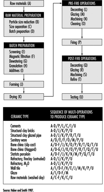
In the final stages, the ware is sorted and packed for shipping. Figure 15 identifies the various paths followed by various types of pottery and ceramics during their fabrication.
Figure 15. Flow chart by type of ceramic
Ceramic Tile
General profile
Ceramic is a term once thought to refer only to the art or technique of producing articles of pottery. The etymology of the term shows that it derives from the Greek keramos, meaning “a potter” or “a pottery”. However, the Greek word is related to an older Sanskrit root, meaning “to burn”; as used by the Greeks themselves, its primary meaning was simply “burnt stuff” or “burnt earth”. The fundamental concept contained in the term was that of a product obtained through the action of fire upon earthy materials.
A traditional ceramic, in the context of this article, refers to the products commonly used as building materials or within the home and industry. Although there is a tendency to equate traditional ceramics with low technology, advanced manufacturing technologies are often used in this industry. Stiff competition among producers has caused the technology to become more efficient and cost effective by utilizing complex tooling and machinery, coupled with computer-assisted process control.
The oldest ceramic products originated from clay-bearing materials. Early potters found the plastic nature of clay to be useful in forming shapes. Because of its tendency to exhibit a large amount of shrinkage, clay bodies were modified by adding coarse sand and stone, which reduced shrinkage and cracking. In modern clay-based bodies, the typical non-clay additions are silica flour and alkali minerals that are added as fluxes. In traditional ceramic formulations, clay acts as a plasticizer and binder for other constituents.
Development of the industry
The production of dried and fired clay tiles has very ancient origins dating back to Middle Eastern populations. The tile whiteware industry developed significantly in Europe, and by the beginning of the 20th century floor and wall tile production achieved industrial scale. Further development in this field occurred after the Second World War. Europe (Italy and Spain, in particular), Latin America and the Far East are now the most important areas of industrial tile production.
The floor and wall tile sector of the whiteware industry has seen a great deal of development since the mid-1980s with the introduction of new technologies, automation and integration of production flow into the manufacturing process. Subsequently, productivity and efficiency increased, while energy consumption and costs have been reduced. Tile manufacturing is now continuous in both wet and dry tile production, and many plants today have nearly 100% automation. The major innovations in the tile industry during the last decade include wet grinding, spray drying, high-pressure dry pressing, roller drying and fast-firing technologies.
The value of the US ceramic tile market supply (US factory shipments plus imports) increased an estimated 9.2% compounded annually between 1992 and 1994. Dollar sales were estimated to have reached US$1.3 billion in 1994. At the same time, volume sales rose 11.9% compounded annually to 1.3 billion square feet. This compares with a market growth rate of 7.6% based on dollar sales, and 6.9% based on volume sales between 1982 and 1992.
Classifications of ceramic tiles
Redware and whiteware
Many types of ceramic tile are available on the market. They differ according to the condition of the surface, colour of the body (white or red), manufacturing technology, raw materials and end use. The difference between “red” and “white” tiles lies in the amount of iron minerals contained in the body. By reacting with the other body components, they can give more or less colouration and modify the behaviour of the body during firing.
A complete and exhaustive classification is very difficult owing to the extreme heterogeneity of the tile products, their processing and subsequent characteristics. In this chapter, European (EN) and ASTM standards are considered.
EN standards exclusively classify ceramic tiles as a function of water absorption (which directly correlates to the porosity) and shaping method (extrusion or pressing). The shaping methods are classified as:
- shaping process A (extruded floor tiles). This process includes split tiles and individually extruded tiles.
- shaping process B (dry-pressed floor and wall tiles).
European Standard EN 87, approved in November 1981, specifies that “Ceramic wall and floor tiles are building materials that are generally designed for use as floor and wall coverings, both indoors and outdoors, regardless of shape and sizes”.
The American National Standards Institute (ANSI) specification for ceramics tile (ANSI A 137.1) contains the following definitions:
- Ceramic mosaic tile is formed by either the dust-pressed or plastic method, usually 6.4 to 9.5 mm (1/4 to 1/8 in.) thick, and has a facial area of less than 39 cm2 (6 in2 ). Ceramic mosaic tiles may be either porcelain or natural clay composition, and they may be either plain or with an abrasive mixture throughout.
- Decorative wall tile is glazed tile with a thin body that is usually non-vitreous and suitable for interior decorative residential wall use where breaking strength is not a requirement.
- Paver tile is glazed or unglazed porcelain or natural clay tile formed by the dust-pressed method having 39 cm2 (6 in2 ) or more facial area.
- Porcelain tile is ceramic mosaic tile or paver tile that is generally made by the dust-pressed method with the resulting tile composition that is dense, impervious, fine-grained and smooth, with a sharply formed face.
- Quarry tile is glazed or unglazed tile, made by the extrusion process from natural clay or shale, usually having 39 cm2 (6 in2) or more facial area.
- Wall tile is glazed tile with a body that is suitable for interior use and usually non-vitreous and is not required to withstand excessive impact or be subject to freezing and thawing conditions.
- Individual tile whiteware grades include unglazed tiles (ceramic mosaic tile, quarry tile, paver tile) and glazed tiles (glazed wall tile, glazed ceramic mosaic tile, glazed quarry tile, glazed paver tile) (ANSI 1988).
The tiles are manufactured by standard ceramic processes. Ceramic wall and floor tiles are prepared from a mixture of ball clays, sand, fluxes, colouring agents and other mineral raw materials, and they undergo processing such as milling, screening, blending and wetting. They are shaped by a pressing, extrusion, casting or other process, normally at room temperature, and are subsequently dried and finally fired at high temperature. Tiles may be glazed, unglazed or engobed. Glazes are glasslike, impervious coatings, and engobes are matte, clay-based coatings that may also be porous. Glazed wall and floor tiles are produced either by single-or two-stage firing.
Traditional ceramic bodies are formed into shapes using many different techniques. The specific forming process is dictated by numerous factors, including material characteristics, size and shape of the part, part specifications, production yield and accepted practices within the geographic region.
Clay-based bodies are heterogeneous mixtures of one or more clays and one or more nonclay powders. Before attaining a final shape, these powders undergo a sequence of unit operations, firing and post-fire operations (see figure 17).
For most traditional bodies, forming techniques can be classified as soft plastic forming, stiff plastic forming, pressing and casting.
Applied pressure is employed to rearrange and redistribute the raw materials into a better-packed configuration. The rheological behaviour of clay-based bodies results from clay mineral inter-action with water, which imparts plasticity to the batch. In nonclay bodies, this same type of behaviour can be achieved by adding plasticizers.
Industrial Ceramics
General profile
Ceramics differ from other engineering materials (metals, plastics, wood products, textiles) in a number of individual properties. Perhaps the most distinctive difference to a designer or potential user of ceramic ware is the unique shape and size of each individual ceramic piece. Ceramics are not readily shaped or worked after firing, except by very costly grinding; consequently, they normally must be used as is. Except for some simple tile, rod and tube shapes of limited sizes, ceramics cannot be marketed by the foot or by the yard, nor cut to fit on the job.
All the useful properties, including shape and size, must be provided in advance, beginning with the very early stages of ceramic processing. The structural integrity of each piece must be preserved through a variety of thermal and mechanical stress exposures during processing and until the piece is finally installed and in service. If a ceramic should fail in service as a result of a variety of causes (brittle fracture on impact, thermal shock, dielectric breakdown, abrasion or melting slag corrosion), it is not likely to be repairable, and usually must be replaced.
Significant advances have been made in fundamental understanding and technological control of the properties of ceramics, and of their utilization in many new, demanding, highly technical applications. The industry in general, and the technical and electronic ceramic portions of it in particular, have devised production and control techniques for mass producing complex shapes in bodies having carefully controlled electrical, magnetic and/or mechanical properties while maintaining dimensional tolerances that are good enough to permit relatively easy assembly with other components.
Many ceramics are produced in large volume as standard items. Refractory bricks and shapes, crucibles, muffles, furnace tubes, insulators, thermocouple protection tubes, capacitor dielectrics, hermetic seals and fibre boards are routinely stocked by a number of ceramic producers in a variety of compositions and sizes. It is usually quicker and cheaper to use stock items whenever possible. When stock items will not meet the need, most manufacturers are prepared to custom produce items. The more stringent the requirements for a given property of the ceramic, or the more restrictive the requirements for specific combinations of properties, sizes and shapes, the more limited are the accepted compositional, microstructural and configurational parameters for the ceramic. Hence the cost and difficulty of manufacture are greater. Most ceramic manufacturers have experienced staff engineers and designers who are well qualified to work with potential customers on details of ceramic ware design.
Markets
The major market for state-of-the-art ceramics has been and will continue to be in electronics, but vigorous worldwide research and development programmes are continuously searching for new applications and identifying ways of improving ceramic properties such that new markets can be accessed.
Advanced ceramics are produced in Japan, the United States and Western Europe. The raw materials used in the industry are traded on an international basis, principally as powders, but there is also a significant amount of in-house processing.
The major applications of industrial ceramics are:
- Oxides. The main oxide materials in use today are alumina in spark plugs, substrates and wear applications; zirconia (ZrO2) in oxygen sensors, as a component in lead-zirconium-titanate (PZT) piezoelectrics, wear applications and thermal barrier coatings; titanates in barium titanate capacitors and PZT piezoelectrics; and ferrites in permanent magnets, magnetic recording heads, memory devices, temperature sensors and electric motor parts.
- Carbides and nitrides. Carbides (mainly silicon carbide and boron carbide) are used in wear applications, while nitrides (mainly silicon nitride and Sialon) are used in wear applications and cutting tools. Aluminium nitride, with its high thermal conductivity, is the primary contending material for part of the electronics substrate market currently dominated by alumina.
- Mixed oxide ceramics. Ceramics research and development efforts are focused on a number of new applications for ceramics that all have enormous potential. Three significant applications are: (1) ceramic superconductors, (2) ceramics for solid oxide fuel cells and (3) ceramic components for heat engines.
Ceramic superconductors are based on a number of mixed oxide systems that include yttrium, barium, copper, strontium and copper (YBa2Cu3O7-8, Bi2Sr2CaCu2O8, Bi2Sr2Ca2Cu3O10) stabilized with lead oxide. Solid oxide fuel-cell ceramics are based on ionic conductors in which high-purity stabilized zirconia is currently the material of choice. Ceramic heat-engine components under investigation are composed of silicon carbide, Sialons and zirconia, either as single-phase ceramics, ceramic-ceramic composites or metal-matrix composites (MMCs).
Manufacturing processes
Manufacturing technology development
Processing innovations. Research and development activity is generating new technologies for the production of ceramic materials. Precursor-derived ceramics were estimated to have a market value of US$2 million in 1989, the major part of which was in CVD (86% of the total market value). Other segments of this growing market include chemical vapour infiltration (CVI), sol-gel and polymer pyrolysis. Products that are being successfully produced by these means include continuous ceramic fibres, composites, membranes and ultra-high-purity/high-activity powders.
The processes used to convert these raw materials to finished products include additional powder processing (e.g., milling and spray drying) prior to forming green shapes that are then fired under controlled conditions. The forming processes include die pressing, isostatic pressing, slip casting, tape casting, extrusion, injection moulding, hot pressing, hot isostatic pressing (HIP), CVD and so on.
Chemical additives to aid ceramic processing. Each step in the manufacturing process requires careful control so that end-product properties are obtained at maximum production efficiency and key effect chemicals are used to optimize powder treatment and green forming. The effect chemicals include milling aids, flocculants and binders, lubricants to effect product release during pressing and minimize wear of die parts, and plasticizers to aid extrusion and injection moulding. A list of such chemicals is shown in table 3. While these materials play an important economic role in production, they are burnt out during firing and play no part in the final product chemistry. The burn out process has to be carefully controlled to avoid residual carbon in the finished products, and process research and development is continuously investigating ways of minimizing the levels of effect chemicals used.
Table 3. Selected chemical additives used to optimize powder treatment and green forming of ceramics
|
Material |
Application or function |
|
Polyvinyl alcohol |
Binder for advanced ceramics |
|
Polyethylene glycol |
Binder for advanced ceramics |
|
Sodium polyacrylate |
Deflocculant for slip casting |
|
Tertiary amide polymer |
Binder for dry pressing |
|
Starch blended with dry colloidal aluminosilicate |
Binder for vacuum forming |
|
Cationic alumina plus organic flocculant |
Binder for vacuum forming |
|
Pre-gelled, cationic corn starch |
Flocculant for colloidal silica and alumina binder |
|
High-purity sodium carboxymethylcellulose |
Binder |
|
Inorganic colloidal magnesium aluminium silicate |
Suspending agent |
|
Medium-viscosity sodium carboxymethylcellulose added to Veegum |
Suspending agent, viscosity stabilizer |
|
Ammonium polyelectrolyte |
Dispersing agent for casting slips for electronic ceramics |
|
Sodium polyelectrolyte |
Dispersing agent binder for spray-dried bodies |
|
Microcrystalline cellulose and sodium carboxymethylcellulose |
Thickening agent |
|
Polysilazane |
Processing aid, binder and precursor for advanced ceramics |
In addition to spawning ceramic products and ceramic manufacturing technologies for new applications, the influence of the advanced ceramics industry on the traditional ceramics industry should not be overlooked. It is expected that many high-technology materials and processes will find application in the traditional ceramics industry as the latter strives to reduce manufacturing costs, to improve quality and to give better value in service to the end user.
Raw materials
There are certain key materials that are either used directly by the ceramics industry or that represent the starting point for the production of added-value materials:
- silica
- clay
- alumina
- magnesia
- titania
- iron oxide
- zircon/zirconia.
This discussion will focus on the properties of silica, alumina and zircon/zirconia.
Silica, in addition to its use in refractories and whitewares, is also the starting point in the manufacture of elemental silicon, silicon carbide and silicon tetrachloride. Silicon, in turn, is the starting point for silicon nitride, and silicon tetrachloride is the precursor for a wide range of silicon organics that can be pyrolyzed under controlled conditions to high-quality silicon carbide and silicon nitride.
Silicon nitride and its Sialon derivatives, as well as silicon carbide, despite their tendency to oxidize, have the potential to meet many of the property targets set by the heat-engine market. A feature of silica and the ceramic materials that are derived from silica is that all the elements are readily available in the earth’s crust. In this respect, these materials offer the potential of ease of supply in all parts of the world. In practice, however, there is a significant energy input required to produce silicon and silicon carbide. Consequently, manufacture of these materials is by and large limited to countries with cheap and readily available electric power.
Alumina is found throughout the earth’s crust as a component in aluminosilicate minerals. Economics dictate that alumina be extracted from bauxite using the Bayer process. Bauxite is widespread in the equatorial belt in different states of purity, and is divided into two classifications: refractory grade ore and metallurgical ore.
Refractory grade bauxite is supplied by China and Guyana as a high-temperature calcine of the naturally occurring mineral: diaspore (Al2O3·H2O) in China and gibbsite (Al2O3·3H2O) in Guyana. During calcination, a complex phase assemblence of corundum (Al2O3), mullite, silica glass and minor levels of aluminium titanate is formed. The consumption of refractory grade bauxite exceeds 700,000 tonnes per year on a worldwide basis.
Metallurgical grade bauxite is mined in Australia, Jamaica and West Africa, and has variable alumina levels in conjunction with major impurities such as iron oxide and silica. The alumina in the metallurgical ores is extracted from the ore when dissolved by sodium hydroxide, yielding a sodium aluminate solution that is separated from the iron oxide and silica, which are rejected as a waste product in the form of red mud. Essentially, pure aluminium hydroxide is precipitated from the sodium aluminate and then calcined to a number of grades of alumina.
The high-purity aluminas used in the ceramics industry and derived by the Bayer process are classified as tabular alumina, fused alumina or speciality calcined alumina.
Tabular alumina is produced by high-temperature (~2,000°C or 3,630°F) calcination of low-temperature calcined alumina in large, oil-fired rotary kilns. Fused alumina is produced by the electric melting of calcined alumina. Tabular and fused alumina are sold to the refractory industry in crushed and graded form for use in a wide range of high-quality products, such as in continuous casting refractories (e.g., single-edge-notched or SEN/slide gates), monolithic refractories for application in blast furnaces and the petrochemical industry.
Speciality calcined alumina powders are the major raw materials used in the advanced ceramics industry for both electronic and engineering applications. The powders are produced in a wide range of grades according to exacting specifications of chemistry, particle size and crystal type, to suit a wide range of end-product applications.
There is an established international trade in high-quality aluminas. Many of the ceramic manufacturers have in-house milling and spray drying facilities. There is clearly a limitation to the growth in the supply of spray-dried systems and a continuing need to supply aluminas which match the customer plants so that use of the latter can be optimized at an acceptable price. Alumina is a significant ceramic material that is available at a high degree of purity. The dominant position of alumina as a ceramic raw material arises because it has desirable properties at a relatively low cost. This cost effectiveness is attributable to the commodity nature of the business arising from the large demand for alumina by the aluminium industry.
Zircon and zirconia. The primary source of zirconia is the mineral zircon (ZrO2 SiO2), which exists in beach sands principally in Australia, South Africa and the United States. Zircon extracted from beach sands contains about 2% hafnium oxide and traces of Al2O3 (0.5%), Fe2O3 (0.1%) and TiO2 (0.1%). In addition, all zircons contain traces of uranium and thorium. Zircon is processed by fine grinding to produce a range of milled products of defined particle size. These products have found use in investment casting, foundries, refractory products and as an opacifier in glazes for whitewares.
Zircon is also the principal source of zirconia. Zircon can be chlorinated in the presence of carbon to give zirconium and silicon tetrachlorides that are then separated by distillation. The zirconium tetrachloride produced can be used to prepare zirconia directly or as a feedstock for other zirconium chemicals. Sintering with alkali or alkaline earth oxides is also used to decompose zircon. Silica is leached from the decomposition products with water, leaving zirconium hydroxide to be further purified by acid dissolution and reprecipitation. Zirconia is then obtained by calcining the hydroxide. Zircon is also converted to zirconia and silica in a plasma at 1,800°C (3,270°F) with rapid cooling to prevent reassociation. The free silica is removed by dissolution in sodium hydroxide. Fused zirconia is produced in electric arc furnaces from either baddeleyite or zircon/carbon feedstocks. In the latter process the silica component of zircon is carbothermally reduced to silicon monoxide, which volatilizes prior to the fusion of the residual zirconia.
Summary
The industrial ceramic industry is very diverse and there is much in-house processing. Many of the final manufacturing operations are in foundry-type atmospheres. The material-handling systems in these operations convey fine raw materials where dust can be an issue. Materials are then raised to very high temperatures and melted or fused into shapes needed for the final parts. Therefore, many of the safety issues which exist in any high-temperature industry also exist in the industrial ceramics industry.
Brick and Tile
General profile
Bricks and tiles made from clay have been used as building material since the earliest times in many parts of the world. When properly made and fired they are more durable than some stones, resistant to weather and great changes of temperature and moisture. The brick is a rectangle of standard size, varying slightly from region to region but essentially convenient for handling with one hand by a bricklayer; roofing tiles are thin slabs, either flat or curved; clay tiles may also be used for floors.
The brick industry is very fragmented. There are many small suppliers located all over the world. Brick manufacturing tends to involve local suppliers and local markets due to the cost of shipping of the finished product. In 1994, there were 218 brick manufacturing plants in the United States, and in 1992 the number of producers of structural clay products in the UK was listed at 182, for example. Brick manufacturers generally are located near the clay deposits to reduce raw material shipping cost.
In the United States, bricks are used primarily in residential construction as either a load-bearing material or as a facade material. Since the brick industry is so closely coupled to the housing industry, manufacturing activity is highly dependent on the residential construction industry and almost totally dependent on the combined residential and non-residential construction industry.
Manufacturing processes
Materials and processing
The basic material is clay of various kinds with mixtures of loams, shales and sand, according to local supply and needs, to give the required properties of texture, plasticity, regularity and shrinkage, and colour.
Extraction of clay is now often fully mechanized; manufacture usually takes place alongside the extraction hole, but in large works the clay is sometimes conveyed in skids on ropeways. The subsequent processing of the clay varies according to its constitution and the end-product, but in general includes crushing, grinding, screening and mixing. See figure 16 for a typical brick-manufacturing operation.
Figure 16. The manufacture of bricks & tiles
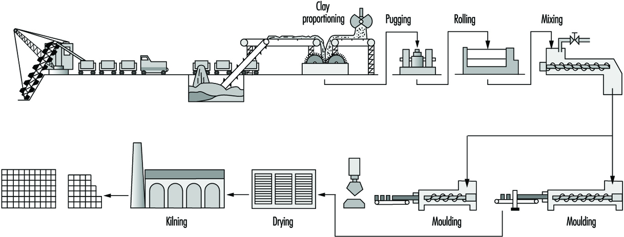
Clay for wire-cut bricks is broken up by rollers; water is added in a mixer; the mixture is rolled again and then fed through a horizontal pugmill. The plastic clay extruded is then cut to size on a wire-cutting table. Semi-dry and stiff plastic material is produced by rolling and screening and is then fed to mechanical presses. Some bricks are still hand moulded.
Where plastic material is used, the bricks have to be dried either by sun and air, or more frequently in regulated kilns, before firing; bricks made from semi-dry or stiff plastic may be fired immediately. Firing may take place in ring kilns, often hand fed, or in tunnel kilns, mechanically fed. The fuels used will vary according to local availability. A finishing glaze is applied to some decorative bricks.
Refractories
General profile
Refractory materials are traditionally thought of as non-metallics that resist degradation by corrosive gases, liquids or solids at elevated temperatures. These materials must withstand thermal shock caused by rapid heating or cooling, failure attributable to thermal stresses, mechanical fatigue due to other material contacting the refractory itself and chemical attack activated by the high-temperature environment. These materials are required for the manufacture of most ceramic products and are specifically needed in ovens, dryers, furnaces and high-temperature-bearing engine parts.
Refractories remained almost exclusively mineral-based until well into the 20th century. Yet technologists who were skilled in mineralogy were paying attention. Metallurgists had been experimenting with acid and basic slagging practices since the Middle Ages and had catalogued some of the benefits of each. Refractory artisans had correspondingly experimented with ganister, with other nearly pure silica minerals and with magnesite, a predominantly MgCO3 mineral which was calcined to MgO. When the Bessemer steel-making converter was invented in 1856, combining working temperatures of over 1,600ºC with corrosive acid slagging, “acid” silica refractories were all but ready. When the Siemens open hearth furnace followed in 1857 at even higher temperatures, and steel making went over in both cases to corrosive basic slagging, “basic” magnesite linings were soon introduced. Basic refractories made from dolomite (MgO-CaO) were developed during the First World War, when the European magnesite supply was cut off from the Allies. Later, with the development of other mineral resources worldwide, magnesite reasserted itself.
Table 4. Refractory usage by industry in the United States
|
Industry |
Percentage of total US sales |
|
Iron and steel |
51.6 |
|
Nonferrous metals |
7.5 |
|
Cement |
4.9 |
|
Glass |
5.1 |
|
Ceramics |
9.7 |
|
Chemical and petroleum |
2.1 |
|
Public utilities |
0.9 |
|
Export |
7.4 |
|
All other and unspecified |
10.8 |
Meanwhile, bonded carbon bricks were produced in the United Kingdom starting in 1863 and eventually found their way into the iron-smelting blast furnace as its working temperatures climbed still higher. They also went quickly into the Hall-Héroult cells for the production of aluminium (1886).
Lime had been made for some 5,000 years using clay and then firebrick kilns. Portland cement manufacturing first called for an innovative refractory when rotary kilns were introduced after 1877. The first resistant linings were made of cement-bonded cement clinker. Later on more durable commercial refractories returned to this industry.
Recuperative and regenerative furnaces, originating in the newborn manufacture of steel in the 1850s, were introduced into nonferrous metallurgy and glassmaking in the late 19th century. Fireclay refractories had to be superseded there, too. Magnesite linings were used in copper converters from 1909, and in the first modern glass tanks about 10 years later. Electric arc furnaces were first tried for steel making in 1853 and became common after 1990. A roughly 100-tonne unit installed in the United States in 1927 employed a magnesite lining.
Three-phase arc furnaces were in place before 1950; it was only then that serious demands arose for more sophisticated refractories. In the same time frame, oxygen blowing was introduced into Bessemer and open-hearth furnaces in the 1940s. The basic oxygen furnace (BOF) literally took over steel making in the late 1950s. Oxygen blowing, by its sheer economic importance, impelled the refractories industry for the first time to introduce synthetic materials into its products on a significant scale.
Properties of refractory materials
The properties that characterize quality refractory materials depend on the nature of the application. The most important aspect of the materials is referred to as “refractoriness”. This term refers to the point at which the specimen begins to soften (or melt). Typically, refractories do not have a specific melting point; the phase transition proceeds over a range of temperatures in a phenomenon called softening. This characteristic is often quantified with a pyrometic cone equivalent (PCE), which is a measure of heat content measured by the slumping of a cone during thermal cycling.
A related, and often more useful property, is the temperature of failure under load. Refractories often fail under load at temperatures much less than the temperature that corresponds to the PCE. In obtaining a value for this parameter, the refractory is subjected to a known load and is subsequently heated. The temperature at which sagging or general deformation occurs is reported. This is of great interest because the value is used to predict mechanical properties during use of the refractory. The load-bearing ability of refractory materials is directly proportional to the amount of viscosity of the glass present.Another factor that is essential to understanding the performance of a refractory is the dimensional stability. Throughout industrial use, refractory materials are subjected to heating/cooling cycles, which cause the refractory units to either expand or contract. Large changes in the dimensions will reduce stability and may ultimately lead to failure of the refractory-based structure.
A related phenomenon commonly observed with refractory materials is spalling. Spalling is generally considered fracture, splitting or flaking of the refractory, resulting in the exposure of the inner mass of the material. Spalling is usually brought about by temperature gradients within the material, compression in the structure due to large-volume charges and variations of the thermal expansion coefficient within the brick. Every effort is made in refractory manufacture to avoid spalling because it reduces the effectiveness of the refractory.
Refractories have application across a wide variety of industrial applications ranging from extensive use in the iron and steel industry to low volume usages in the cement and public utilities industries. Basically, refractories are used in any industry where high temperatures are used to heat and dry or incinerate material. Table 4 provides a current breakdown by industry of refractory usage within the United States.
As shown in table 4 the steel industry is the area where over 50% of the refractory produced in the U.S. is utilized. Therefore, the needs of the steel industry to a great extent have driven the refractory developments which have occurred.
Modern refractories
Ceramics had grown substantially from craft to applied science. The American Ceramic Society had been founded in 1899, the British Ceramic Society in 1901. Oxide phase diagrams began to appear in the literature in the 1920s. The techniques of petrography were well developed, and the detailed mechanisms of refractory degradation and wear were beginning to be understood. American refractory producers had become largely reorganized, consolidated and capable of performing their own research. The tools of refractory synthesis and instruments of investigation were both burgeoning.
Synthetic industrial carbons were, of course, not new. Coke was first made commercially from coal in the 1860s, and from petroleum shortly thereafter. Synthetic graphite and silicon carbide appeared almost simultaneously at the turn of the century, following Acheson’s invention of the self-resistance-heated electric furnace in 1896. These products, having properties quite unlike those of oxides, rapidly stimulated their own uses and markets.
Synthetic alumina, Al2O3, had been available since the Bayer process started feeding aluminium production about 1888. Synthetic magnesia (MgO) was first made from seawater in the United Kingdom in 1937 and in the United States in 1942, stimulated by wartime needs for magnesium. Zirconia had become available, also spurred by the military. Lime had been a major commodity for ages. A host of other chemicals were on hand for consideration as refractory components or as minor additives and bonding agents. The only important component of oxide refractories that for the most part has resisted replacement by synthetics is silica (SiO2) High-purity silica rocks and sands abound and are used in this industry as well as in glass formulation.
The use of synthetics in refractory manufacture has been enormously helpful; but mineral raw materials have by no means been displaced. Synthetics cost more, and that cost has to be justified. Some synthetic materials create severe problems in refractory processing, and new ways must be found to overcome these. Optimum results have often been achieved by combinations of synthetic and mineral raw materials, along with creative inputs into their processing.
Mixtures of clay with carbon had been used to line crucibles and ladles since iron was first poured; and silica bricks containing carbon were made in France in the 1860s. Since 1960 both the techniques and the compositions have changed dramatically. The use of carbon-bearing oxide refractories has mushroomed, starting with MgO+C. The first real impetus may have been provided by the BOF; but today there is hardly any advanced oxide refractory type that cannot be had either with or without added carbon or a carbon precursor for superior performance in specific applications.
Arc-fused refractory grain or aggregate had been made since the early 1900s, and fused-cast refractory bricks of several compositions followed in the twenties and thirties, notably of mullite, alumina, magnesia-alumina-silica and alumina-zirconia-silica. More often than not, these products were made entirely from mineral raw materials.
In fact, all-mineral-based refractories remain today an important component of the product menu. They are on the whole cheaper, they often perform admirably and there are still many applications of lesser demand as well as those of critical demand for the highest levels of refractoriness and corrosion resistance.
Refractory industry
Refractories will be found in use in many industries for lining boilers, kilns and furnaces of all kinds, but the largest percentage are used in manufacture of metals. In the steel industry, a typical blast or open-hearth furnace may use many different types of refractories, some made from silica, some from chrome and/or magnesite and others of fire clay.
Much smaller quantities are also used in the following industries: gas, coke and by-products; power-generating plants; chemicals; bake ovens and stoves; cement and lime; ceramics; glass; enamels and glazes; locomotives and ships; nuclear reactors; oil refineries; refuse disposal (incinerators).
Manufacturing processes
The type of refractory that is used in any particular application depends on the critical requirements of the process. For example, processes that demand resistance to gaseous or liquid corrosion require low porosity, high physical strength and abrasion resistance. Conditions that demand low thermal conductivity may require entirely different refractories. Indeed, combinations of several refractories are generally employed. There is no well-established line of demarcation between those materials that are and those that are not refractory, although the ability to withstand temperatures above 1,100°C without softening has been cited as a practical requirement of industrial refractory materials.
The technical goals of manufacture of a given refractory are embodied in its properties and performance in an intended application. The tools of manufacture consist of choices among raw materials and among processing methods and parameters. The requirements of manufacture have to do with the features of phase composition and microstructure—collectively called material character—that are developed through processing and are themselves responsible for product properties and behaviour.
Raw materials
In the past, refractory raw materials were selected from a variety of available deposits and used as mined minerals. Selective mining yielded materials of the desired properties, and only in cases of expensive raw materials, such as magnesite, was a beneficiation process required. Today, however, high-purity natural raw materials are increasingly in demand as are synthetically prepared refractory grain made from combinations of high-purity and beneficiated raw materials. The material produced upon firing raw as-mined minerals or synthetic blends is called grain, clinker, co-clinker or grog.
Refractories are usually classified into four types: alumino-silicate, silica (or acid), basic and miscellaneous.
The materials generally used in the four types of refractories include:
- Aluminosilicate refractories. Fireclays consist mainly of the mineral kaolinite [CAS 1318-74-7] (Al203 2SiO2 2H2O) with small amounts of other clay minerals, quartzite, iron oxide, titania and alkali impurities. Clays can be used in the raw state or after being calcined. Raw clays may be coarsely sized or finely ground for incorporation in a refractory mix. Some high-purity kaolins are slurried, classified, dried and air floated to achieve a consistent, high quality. The classified clays also may be blended and extruded or pelletized and then calcined to produce burned synthetic kaolinitic grog, or coarsely crushed raw kaolinite may be burned to produce grog. Upon calcination or burning, kaolinite decomposes to mullite and a siliceous glass incorporating mineral impurities associated with the clay deposit (e.g., quartzite, iron oxide, titania and alkalis) and is consolidated into dense, hard granular grog at high temperatures.
- Silica or acid refractories use mainly silica in the form of crushed and ground quartzite (ganister) (92 to 98%), to which a suitable bonding substance, such as lime (CaO), is added. Silica bricks are generally heated twice because they expand when heated (fireclay bricks shrink), and it is desirable that the expansion be completed before the wall or lining is built.
- Basic refractories use dolomite, magnesite (MgO), chrome oxide, iron and aluminium.
- Miscellaneous refractories. Of the great variety of materials now in use, the more common ones are carbides such as silicon carbide, graphite, alumina, beryllia, thoria, uranium oxide, asbestos and zirconium oxide.
Several revolutions in the industry have occured. Included in these revolutions are further mechanized methods of handling tonnage solids, increased capabilities and automation of processing equipment and techniques for the rapid acquisition and analysis of in-process control data. These advances have transformed refractory manufacturing practice.
Figure 17 illustrates how different kinds of refractories are made. The figure is drawn in “decision tree” style with the diverging branches keyed by numbers for identification. There are various paths, each making a particular type of refractory product.
Figure 17. Refractory manufacturing flow diagram
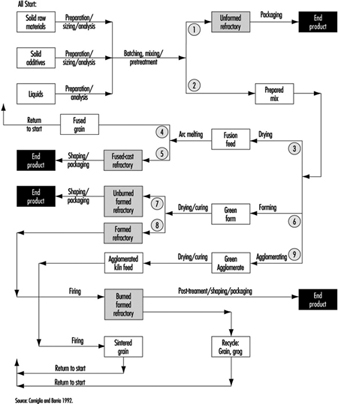
These generic flow diagrams represent thousands of specific processes, differentiated, for example, by their raw materials lists, the manner of preparation and the sizing and batching (meaning quantity weighed out) of each, the sequence and manner of mixing and so on. Omissions are allowed—for example, some unformed refractories are dry-mixed and never wetted until installation.
Refractories or products may be preformed (shaped) or formed and installed on site, but in general are supplied in the following shapes:
Brick. The standard dimensions of a refractory brick are 23 cm long by 11.4 cm wide and 6.4 cm thick (straight brick). Bricks may be extruded or dry-pressed on mechanical or hydraulic presses. Formed shapes may be burned before use or, in the case of pitch, resin or chemically bonded brick (cured).
Fusion-cast shapes. Refractory compositions are arc-melted and cast into shapes (e.g., glass-tank flux blocks as large as 0.33, 0.66, 1.33 m). After casting and annealing, the blocks are accurately ground to ensure a precise fit.
Cast and hand-moulded refractories. Large shapes, such as burner blocks and flux blocks, and intricate shapes, such as glass feeder parts, saggers and the like, are produced by either slip or hydraulic cement casting or hand-moulding techniques. Because these techniques are labour intensive, they are reserved for articles that cannot be satisfactorily formed in other ways.
Insulating refractories. Insulating refractories in the form of brick are much lighter than conventional brick of the same composition by virtue of the brick porosity.
Castables and gunning mixes. Castables consist of refractory grains to which a hydraulic binder is added. Upon mixing with water, the hydraulic agent reacts and binds the mass together. Gunning mixes are designed to be sprayed through a nozzle under water and air pressure. The mixture may be slurried before being shot through the gun, or mixed with water at the nozzle.
Plastic refractories and ramming mixes. Plastic refractories are mixtures of refractory grains and plastic clays or plasticizers with water. Ramming mixes may or may not contain clay and are generally used with forms. The amount of water used with these products varies but is held to a minimum.
Occupational Hazards and Precautions
Table 5 provides information on many of the potential hazards found in this industrial sector.
Table 5. Potential health and safety hazards found during manufacturing of glass, ceramic and related materials
|
Hazards |
Uses or sources of exposure |
Potential effects (physical hazards |
Precautions or control strategies |
|
Ergonomic stressors; biomechanical hazards |
Overexertion from manual material-handling practices and excessive force, poor posture, high frequency/duration of tasks involving lifting, pushing or pulling |
Strains, sprains and run in skeletal muscular damage to back, upper and lower extremities Excessive physical and mental fatigue can cause errors leading to secondary incidents |
|
|
Physical hazards |
Caught in or struck by or against fixed or mobile equipment Slips, trips and falls on walking and working surfaces, hoses and other equipment, tools or materials |
Abrasions, cuts, contusions, lacerations, punctures, fractures, amputations |
|
|
Noise |
Pneumatic vibrators, compressors, valve actuators, mixing drive motors, blowers and dust collectors, conveyors, powered industrial trucks, mechanized process and packaging equipment, etc. |
Occupational hearing loss, communication difficulty and stress |
|
|
Radiant heat, high-temperature work environments |
Heating or melting processes during maintenance or emergency response activities |
Physiological strain, heat stress or thermal burns |
|
|
Inhalation of airborne particulate matter from raw materials including crystalline silica, clay, lime, iron oxide, nuisance dusts |
Handling raw materials and during production Exposures during routine maintenance activities, demolition and during construction activities or rebuilds Exposures can occur from non-ventilated equipment or from leaks or poor seals at transfer points, chutes, conveyors, elevators, screens, sieves, mixing equipment, grinding or crushing machines, storage bins, valves, piping, drying or curing ovens, shaping operations, etc. Raw materials are extremely abrasive, causing deterioration of transfer or storage system components in manufacturing processes. Failure to maintain baghouses, scrubbers or dust collectors and use of compressed air for clean-up activities increases risk of overexposures Intense heating processes may lead to exposure to the most hazardous forms of silica (cristobalite or tridymite) |
Range from irritation (nuisance particulate) to chemical burns (burnt lime or other alkaline raw materials) to chronic effects such as decreased pulmonary function, lung disease, pneumoconiosis silicosis, tuberculosis |
|
|
Lacerations, abrasions, or foreign bodies; contact with sharp glass, pottery or ceramics fragments or objects |
Flying glass, ceramics or other fragments may cause penetrating wounds and serious eye injury. A special risk exists when toughened glass “explodes” during manufacture Direct contact with glass or other filaments, especially in forming or winding in continuous filament production operations and coating Drawing operations in optical fibre manufacturing |
Puncture wounds, lacerations or abrasion of skin and soft tissues (tendons, ligaments, nerves, muscle), and foreign bodies in the eye Risks of serious secondary infections or dermal exposures to corrosive or toxic materials |
|
|
Lacerations from hand-tools |
Razor knives, finger knives, cullet knives or other sharp hand tools are commonly used in production, packaging and warehousing areas or during maintenance activities |
Cuts to finger(s) or hand(s) and to lower extremities (legs) |
|
|
Heavy metals particulates or fumes (lead, cadmium, chromium, arsenic, copper, nickel, cobalt, manganese or tin) |
As raw materials or impurities in glazes, product formulas, pigments, colouring agents, films or coatings Maintenance and construction activities involving soldering, cutting, welding and applying/ removal of protective coatings Grinding, cutting, welding, drilling, or shaping fabricated metal parts, structural members or machinery (e.g., refractory blocks or high-temperature alloys) that are components of manufacturing processes |
Heavy metal toxicity |
|
|
Formaldehyde via inhalation or direct contact |
Component of binders and sizes in vitreous fibre industry Potential exposures during mixing of binders or sizes, and during production |
Sensory irritation, and irritation of respiratory tract Probable human carcinogen |
|
|
Bases (sodium hydroxide) or acids (hydrochloric acid, sulphuric acid, hydro-fluoric acid) |
Process water, boiler water or wastewater treatment and pH control Acid cleaning or etching processes with hydrofluoric acid |
Corrosive to skin or eyes Respiratory tract and mucous membrane irritant Hydrofluoric acid causes severe shin burns that can go undetected for hours |
|
|
Epoxies, acrylates and urethanes (may contain solvents such as xylene, toluene, etc.) |
Ingredients in resins, sizes, binders and coatings used in production Maintenance products |
Potential sensitizers to skin or respiratory tract Some epoxies contain unreacted epichlorohydrin, a suspect carcinogen Some urethanes contain unreacted toluene diisocyanate, a suspected carcinogen Amine curatives used in some systems—irritants or corrosives Flammability hazard |
|
|
Styrene |
Polyester resins containing styrene, size ingredients |
Irritant to eyes, skin, respiratory tract; effects on central nervous system (CNS) and target organs Possible carcinogen Flammability hazard |
|
|
Silanes |
Adhesion promoters added to sizes, binders or coatings. Can hydrolyze to release ethanol, methanol, butanol or other alcohols |
Irritant to eyes, skin and respiratory system; potential CNS effects. Splashes in eye can cause permanent damage Flammability hazard |
|
|
Latex |
Size or binder mixing areas, coatings and some maintenance products |
Irritant to skin and eyes. Some may contain formaldehyde or other biocides and/or solvents |
|
|
Catalysts and accelerators |
Added to resins or binders for curing in production and/or for some maintenance products |
Irritants or corrosives to skin or eyes. Some are highly reactive and temperature sensitive |
|
|
Hydrocarbon solvents and/or chlorinated solvents |
Maintenance shops and parts-cleaning operations |
Various—irritation, chemical dermatitis, CNS effects. Non-chlorinated solvents may be flammable Chlorinated solvent can decompose if burned or heated |
|
|
Propane, natural gas, gasoline, fuel oil |
Fuels for process heat Fuels for powered industrial trucks |
Fire and explosion hazards Exposure to carbon monoxide or other products of incomplete combustion |
|
|
Inhalation of bioaerosols |
Aerosols containing bacteria, moulds or fungus generated from spraying process or cooling water in humidification processes, cooling towers, ventilation systems, wet clean-up activities |
Waterborne illness with systemic non specific flu-like symptoms, fatigue Potential for dermatitis |
|
|
Fibrous glass, mineral wool fibre, refractory ceramic fibres |
In manufacturing processes including fibre formation, heat curing, cutting or cubing, winding, packaging and fabrication In use of fibrous materials as a component of furnaces, ducts and process equipment |
Non-respirable fibres can cause mechanical irritation to skin or eyes Respirable fibres can cause irritation to eyes, skin and respiratory tract. Durable fibres have caused fibrosis and tumours in animal studies |
|
Safety and Health Problems and Disease Patterns
This section provides an overview of industry-wide documented or suspected safety and health problems. International data on injuries and illnesses in this business sector were not located in literature searches and searches on the Internet (in 1997). Information compiled by the US Department of Labor, Occupational Safety and Health Administration (OSHA) and Bureau of Labor Statistics (BLS), was used to identify common hazards in the workplace and to describe characteristics of injuries and illnesses. These data should be representative of the situation worldwide.
Hazards detected during inspections
Regulatory compliance inspections of companies in the stone, clay, glass and concrete products manufacturing (Standard Industrial Classification (SIC) Code 32, equivalent to ISIC Code 36) reveal some of the common hazards in this sector. Regulatory compliance citations issued by OSHA indicate that common health and safety issues can be grouped as follows:
- hazard communication of physical and health hazards of chemical substances in the workplace
- control of hazardous energy—lockout and tagout procedures to control activities around machinery or equipment where un-expected energization or release of stored energy could cause injury. Hazardous energy includes electrical, mechanical, hydraulic, pneumatic, chemical, thermal radiation and other sources.
- electrical safety, including electrical equipment or system design, wiring methods, safe work practices and training
- permit required confined-space entry—identification, evaluation and safe entry procedures
- personal protective equipment—assessments, selection and use of eye, face, hand, foot and head protection
- guarding machines, equipment and tools to protect operators and adjacent workers from hazards at point of operation, ingoing nip points, and from rotating parts, flying chips or sparks; includes fixed machinery, portable machinery and portable power tools, and adjustment of guards and work rests on abrasive wheel machinery (grinders) (see figure 18)
Figure 18. Machine guarding protects operators
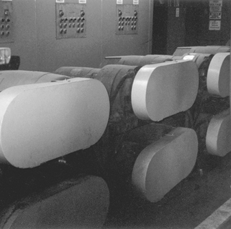
- respiratory protection—selection, use, maintenance, training, medical clearance and fit testing of respirators
- occupational noise exposure—control of exposures by engineering, administrative or hearing protection and implementation of hearing conservation programmes
- fire prevention and emergency preparedness and response, including fire extinguishers, escape routes, plans and flammable/combustible materials storage or use
- walking and working surfaces, including guarding floor and wall openings and holes; housekeeping; and keeping aisles and passageways free from conditions that present slip, trip or fall hazards (see figure 19)
Figure 19. Trip & slip hazards

- powered industrial trucks—design, maintenance, use and other safety requirements for fork-lift trucks, platform trucks, tractors, motorized hand trucks or other specialized industrial trucks powered by electric motors or internal combustion motors
- fixed and portable ladders, stairways and scaffolds—design, inspection or maintenance and safe use
- fall protection—use of fall restraints and arrest equipment for elevated work
- cutting and welding—safe use and procedures for oxygen/acetylene or fuel gas or arc cutting or welding equipment
- material-handling equipment—including overhead and gantry cranes, hoists, chains and slings
- control of exposure to toxic or hazardous substances, including air contaminants or specifically regulated chemicals (e.g., silica, lead, asbestos, formaldehyde, cadmium or arsenic).
Injury and Illness Profile
Injury illness incidence rates
Based on records from the US Department of Labor, manufacturers of stone, clay and glass products (SIC 32) have a total “recordable” incidence rate of nonfatal occupational injuries and illnesses of 13.2 cases per 100 full-time workers per year. This incidence rate is higher than corresponding rates for all manufacturing (12.2) and all private industry (8.4). About 51% of the “recordable injury” cases in the stone, clay and glass product manufacturing sector do not result in lost work days (time away from work).
The “total lost workday case” incidence rates based on the number of disabling injuries or illnesses resulting in a worker missing days of work per 100 full-time workers are also available from the US Department of Labor. The total lost workday incidence rate includes cases where workdays are lost and the worker is not capable of performing the full scope of the job (restricted or light duty). Stone, clay and glass products manufacturers have a total lost workday incidence rate of 6.5 cases per 100 workers per year. This is higher than the corresponding rates for all manufacturing (5.5) and for all private industry (3.8). About 93% of the lost workday cases in the stone, clay and glass product manufacturing sector results from injuries rather than occupational illnesses.
Table 6 presents more detailed information on incidence rates for injuries and illnesses (combined) or injuries (alone) for various types of manufacturing processes within the stone, clay, and glass product manufacturing sector (SIC Code 32). Incidence rates and demographics may not be representative of global information, but it is the most complete information available.
Table 6. Nonfatal occupational injury and illness incidence rates1 per 100 full-time workers for US companies in SIC Code 32, private industry and manufacturing, 1994
|
Industry |
SIC Code2 |
1994 Annual Average Employment3 (thousands) |
Injuries and Illnesses |
Injuries |
||||||
|
Lost Workday Cases |
Lost Workday Cases |
|||||||||
|
Total Cases |
Total4 |
With days away from work |
Cases without Lost Workdays |
Total Cases |
Total5 |
With days away from work5 |
Cases without Lost workdays |
|||
|
Private industry, all |
95,449.3 |
8.4 |
3.8 |
2.8 |
4.6 |
7.7 |
3.5 |
2.6 |
4.2 |
|
|
Manufacturing, all |
18,303.0 |
12.2 |
5.5 |
3.2 |
6.8 |
10.4 |
4.7 |
2.9 |
5.7 |
|
|
Stone, clay and glass products |
32 |
532.5 |
13.2 |
6.5 |
4.3 |
6.7 |
12.3 |
6.1 |
4.1 |
6.2 |
|
Flat glass |
321 |
15.0 |
21.3 |
6.6 |
3.1 |
14.7 |
17.3 |
5.2 |
2.6 |
12.1 |
|
Glass and glassware, pressed |
322 |
76.8 |
12.5 |
6.0 |
3.0 |
6.5 |
11.3 |
5.5 |
2.8 |
5.8 |
|
Glass containers |
3221 |
33.1 |
14.1 |
6.9 |
3.4 |
7.2 |
13.2 |
6.5 |
3.2 |
6.7 |
|
Pressed and blown glass, nec |
3229 |
43.7 |
11.3 |
5.4 |
2.8 |
5.9 |
9.8 |
4.8 |
2.4 |
5.1 |
|
Products of purchased glass |
323 |
60.7 |
14.1 |
6.1 |
3.1 |
8.0 |
12.7 |
5.4 |
2.9 |
7.4 |
|
Structural clay products |
325 |
32.4 |
14.1 |
7.7 |
4.2 |
6.5 |
13.1 |
7.2 |
4.0 |
5.9 |
|
Brick and structural clay tile |
3251 |
- |
15.5 |
8.4 |
5.1 |
7.1 |
14.8 |
7.9 |
5.0 |
6.9 |
|
Clay refractories |
3255 |
- |
16.0 |
9.3 |
4.7 |
6.8 |
15.6 |
9.3 |
4.7 |
6.4 |
|
Pottery and related products |
326 |
40.8 |
13.6 |
6.8 |
3.8 |
6.8 |
12.2 |
6.1 |
3.5 |
6.1 |
|
Vitreous plumbing fixtures |
3261 |
- |
17.8 |
10.0 |
3.8 |
7.8 |
16.1 |
9.0 |
3.5 |
7.1 |
|
Vitreous china table and |
3262 |
- |
12.8 |
6.3 |
4.4 |
6.5 |
11.0 |
5.6 |
3.8 |
5.5 |
|
Porcelain electrical supplies |
3264 |
- |
11.3 |
5.8 |
3.7 |
5.6 |
9.8 |
5.0 |
3.4 |
4.8 |
|
Pottery products, nec |
3269 |
- |
12.6 |
5.6 |
3.7 |
7.1 |
11.6 |
5.0 |
3.5 |
6.6 |
|
Concrete, gypsum and plaster |
327 |
198.3 |
13.4 |
7.0 |
5.6 |
6.4 |
13.0 |
6.9 |
5.5 |
6.2 |
|
Concrete block and brick |
3271 |
17.1 |
14.5 |
7.8 |
6.8 |
6.8 |
14.0 |
7.7 |
6.7 |
6.2 |
|
Concrete products, nec |
3272 |
65.6 |
17.7 |
9.8 |
7.0 |
7.9 |
17.1 |
9.5 |
6.8 |
7.6 |
|
Ready-mixed concrete |
3273 |
98.8 |
11.6 |
6.0 |
5.3 |
5.6 |
11.5 |
6.0 |
5.3 |
5.5 |
|
Misc. nonmetallic mineral |
329 |
76.7 |
10.7 |
5.4 |
3.3 |
5.3 |
9.8 |
5.0 |
3.2 |
4.9 |
|
Abrasive products |
3291 |
20.0 |
10.2 |
3.9 |
2.5 |
6.3 |
9.5 |
3.7 |
2.4 |
5.8 |
|
Mineral wool |
3296 |
23.4 |
11.0 |
6.1 |
3.0 |
4.9 |
10.0 |
5.6 |
2.7 |
4.3 |
|
Nonclay refractories |
3297 |
- |
10.6 |
5.8 |
4.5 |
4.8 |
10.2 |
5.7 |
4.3 |
4.6 |
|
Nonmetallic mineral products, |
3299 |
- |
13.1 |
8.2 |
5.8 |
4.9 |
11.4 |
7.0 |
5.5 |
4.3 |
nec = not elsewhere classified
- = data not available
1 The incidence rates represent the number of injuries and illnesses per 100 full-time workers and were calculated as number of injuries and illnesses divided by hours worked by all employees in the calendar year times 200,000 (the base equivalent for 100 workers at 40 hours per week for 52 weeks per year).
2 Standard Industrial Classification Manual 1987 Edition.
3 Employment is expressed as an annual average and was derived primarily from the BLS State Current Employment Statistics programme.
4 Total cases includes cases involving restricted work activity only, in addition to days away from work cases with or without restricted work activity.
5 Days away from work cases include those which result from days away from work, with or without restricted work activity.
Source = Source: Based on national survey of work-related injuries and illnesses in private industry by the US Department of Labor, Bureau of Labor Statistics.
Demographics of injuries and illness cases
Workers aged 25 to 44 years accounted for about 59% of the 23,203 lost-time injury or illness cases in the U.S. stone, clay and glass product manufacturing sector. The next highest affected group was workers aged 45 to 54 years, who had 18% of the lost-time injury or illness cases (see figure 20).
Figure 20. Lost-time injuries & illnesses by age; US
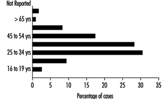
About 85% of the lost-time injury cases injuries and illnesses in SIC Code 32 were males. In 24% of the lost-time cases (both sexes), workers had less than 1 year of service in the job. Workers with 1 to 5 years of service in the job accounted for 32% of the cases. Experienced employees with more than 5 years of service comprised 35% of the lost-time cases.
Nature. Analysis of lost-time incident profiles characterizes the nature of the disabling injuries and illnesses and helps explain causative or contributing factors. Strains and sprains are the leading nature of injury and illness in the stone, clay and glass product manufacturing sector. As shown in figure 23, strains and sprains make up about 42% of all lost-time cases. Cuts and punctures (10%) were the second most common nature of disabling injury or illness. Other major nature of injury categories were bruises (9%), fractures (7%) and back/other pain (5%). Heat burns, chemical burns and amputations were less common (1% or less).
Figure 21. Occupational injuries & illnesses

Events or exposures. Figure 22 shows that overexertion while lifting leads all other disabling injury events or exposures. Over exertion while lifting was a causative factor in about 17% of the disabling cases; repetitive motion was the exposure in an additional 5% of the disabling cases. Struck by an object was the next most common event, which led to 16% of the cases. Struck against an object events caused 10% of the cases. Other important events were caught in an object (9%), falls on same level (9%), falls to lower level (6%), and slips/trips without a fall (6%). Exposure to harmful substances or environment was a causative factor in only 5% of the cases.
Figure 22. Event or exposure in occupational injuries
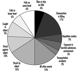
Body part. The body part most frequently affected was the back (24% of the cases) (see figure 23). Injuries to the upper extremities (finger, hand, wrist and arm combined) occurred in 23% of the cases, with injury to the finger in 7% of the cases. Lower-extremity injuries was similar (22% of cases), with the knee affected in 9% of the cases.
Figure 23. Body part affected in lost workday injury
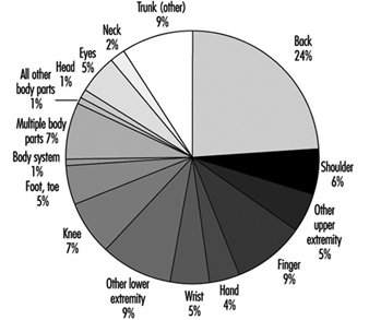
Sources. The most common sources of disabling injury or illness cases were: parts and materials (20%); worker position or motion (16%); floors, walkways or ground surfaces (15%); containers (10%); machinery (9%); vehicles (9%); handtools (4%); furniture and fixtures (2%); and chemicals and chemical products (2%) (see figure 24).
Figure 24. Sources of occupational injuries

Disease prevention and control
Cumulative trauma associated with repetitive motion, overexertion and excessive forces is a common finding in this manufacturing sector. Robotic devices are available in some instances, but manual handling practices still dominate. Compressors, blowers, spinners, pneumatic vibrators and packaging equipment can create noise exceeding 90 to 95 dBA. Hearing protection and a sound hearing conservation programme will prevent permanent changes in hearing.
This industry consumes large quantities of crystalline silica. Exposures must be limited during handling, maintenance and cleaning. Good housekeeping with a proper vacuum system or wet cleaning methods will reduce potential exposures. Periodic screening should be conducted utilizing pulmonary function tests and chest films if excessive exposure to silica has occurred. Exposures to heavy metals found as raw materials, glazing or pigments should also be minimized. Using substitutes for heavy metals found in glazes will also eliminate health concerns regarding leaching of metals into food or beverages. Good housekeeping practices and respiratory protection are used to prevent adverse effects. Medical surveillance that includes biological monitoring may be necessary.
The use of binders containing formaldehyde, epoxies and silanes is common in the manufacture of vitreous fibres. Steps must be taken to minimize skin and respiratory irritation. Formaldehyde is regulated as a carcinogen in many countries. Respirable fibres are produced during manufacturing, fabrication, cutting and installation of glass, rock, slag, and refractory ceramic fibre products. Although exposures to airborne fibres have generally been quite low (less than 1 fibre per cubic centimetre) for most of these materials, loose fill blowing applications tend to be much higher.
Rock, slag, and glass are among the most extensively studied commercial insulation products in use today. Epidemiological studies have revealed that cigarette smoking is having a major impact on lung cancer mortality among manufacturing employees. Well-conducted cross-sectional studies have not shown that the fibres produce excess lung mortality or morbidity. Recent chronic inhalation studies in rats have shown that the durability of vitreous fibres is a critical determinant of the biological potential of these fibres. Composition, which determines the durability of these fibres, may vary considerably. To avoid public health concerns, a European Commission Technical Committee has recently proposed that the bio-persistence of vitreous fibres be tested using short-term inhalation. An insulation wool composition which has been thoroughly tested at maximum tolerated dose by chronic inhalation in rats and found not to produce irreversible disease is suggested as a reference fibre.
Environmental and Public Health Issues
The primary air pollutant emitted during the manufacture of glass, ceramics, pottery and brick is particulate matter. Maximum achievable control technology consisting of baghouses and wet electrostatic precipitators is available to reduce emissions when necessary. Hazardous air pollutants generated during binder mixing, application and curing processes are coming under scrutiny. These substances include styrene, silanes and epoxies used on continuous glass filament, and formaldehyde, methanol and phenol utilized during rock, slag and glass production. Formaldehyde is the hazardous air pollutant that is driving the control standards for the latter manufacturing lines. Heavy metal hazardous air pollutants such as chromium are driving glass melting furnace standards while NOx and SOx remain issues in some countries. Fluoride and boron emissions are of concern in continuous glass filament production. Boron may also become an environmental concern if highly soluble vitreous glass wool fibres are required in some countries.
Due to the high discharge volume of air and the nature of forming and glass melting, the industry evaporates considerable quantities of water. Many facilities, as, for example, in the United States, have zero discharge of wastewater. Recycled wastewater that contains organic material can create biological hazards in the workplace if treatment is not implemented to prevent biological growth (see figure 25). Waste generated by this industrial sector includes heavy metals, corrosives, some binders and spent solvents. The glass fibre industry has become a major point for recycling glass bottles and plate glass. For example, current glass wool products contain 30 to 60% recycled glass. Spent refractories are also reclaimed and beneficially reused.
Figure 25. Aerosols of reused waste water
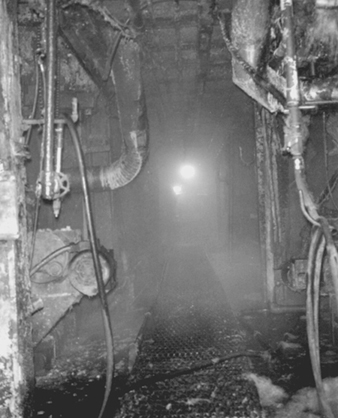
Acknowledgements: Special thanks to Dan Dimas, CSP, Libbey-Owens-Ford, for providing photographs, and to Michel Soubeyrand, Libbey-Owens-Ford, for providing information on chemical vapour deposition for the section on glass.
Environmental and Public Health Issues
Industry Overview
The electronics industry, compared to other industries, has been viewed as “clean” in terms of its environmental impact. None the less, the chemicals used in the manufacture of electronic parts and components, and the waste generated, create significant environment issues that must be addressed on a global scale due to the size of the electronics industry. The wastes and by-products derived from the manufacture of printed wiring boards (PWBs), printed circuit boards (PCBs) and semiconductors are areas of interest that the electronic industry has vigorously pursued in terms of pollution prevention, treatment technology and recycling/reclamation techniques.
To a large degree, the incentive to control the environmental footprint of electronic processes has migrated from an environmental impetus to a financial domain. Due to the costs and liabilities associated with hazardous waste and emissions, the electronics industry has aggressively implemented and developed environmental controls that have greatly reduced the impact of its by-products and waste. In addition, the electronics industry has taken a proactive approach to incorporate environmental goals, tools and techniques into its environmentally conscious businesses. Examples of this proactive approach are the phase-out of CFCs and perfluorinated compounds and the development of “environmentally friendly” alternatives, as well as the emerging “design for the environment” approach to product development.
The manufacture of PWBs, PCBs and semiconductors requires the use of a variety of chemicals, specialized manufacturing techniques and equipment. Due to the hazards associated with these manufacturing processes, the proper management of chemical by-products, wastes and emissions is essential to assure the safety of the industry’s employees and the protection of the environment in the communities in which they reside.
Table 1, table 2 and table 3 present an outline of the key by-products and wastes that are generated in the manufacturing of PWBs, PCBs and semiconductors. In addition, the tables present the main types of environmental impact and the generally accepted means of mitigation and control of the waste stream. Primarily, the wastes that are generated affect industrial wastewater or the air, or become a solid waste.
Table 1. PWB waste generation and controls
|
Process steps |
Hazardous |
Environmental |
Controls1 |
|
Material |
None |
None |
None |
|
Stack and pin |
Heavy/precious metals |
Solid waste2 |
Recycle/reclaim |
|
Drilling |
Heavy/precious metals |
Solid waste2 |
Recycle/reclaim |
|
Deburr |
Heavy/precious metals |
Solid waste2 |
Recycle/reclaim |
|
Electroless |
Metals |
Wastewater |
Chemical precipitation |
|
Imaging |
Solvents |
Air |
Adsorption, condensation or |
|
Pattern plating |
Corrosives |
Wastewater/air |
pH neutralization/air scrubbing |
|
Strip, etch, strip |
Ammonia |
Air |
Air scrubbing (adsorption) |
|
Solder mask |
Corrosives |
Air |
Air scrubbing (adsorption) |
|
Solder coating |
Solvents |
Air |
Adsorption, condensation or |
|
Gold plating |
Corrosives |
Air |
Air scrubbing (adsorption) |
|
Component |
Solvents |
Air |
Adsorption condensation or |
1. Use of mitigation controls depends upon discharge limits in the specific location.
2. A solid waste is any discarded material regardless of its state.
Table 2. PCB waste generation and controls
|
Process steps |
Hazardous |
Environmental |
Controls |
|
Cleaning |
Metals (lead) |
Wastewater |
pH neutralization, chemical |
|
Solder paste |
Solder paste (lead/tin) |
Solid waste |
Recycle/reclaim |
|
Adhesive |
Epoxy glues |
Solid waste |
Incineration |
|
Component |
Plastic tapes, reels and tubes |
||
|
Adhesive cure and |
|||
|
Fluxing |
Solvent (IPA flux) |
Solid waste |
Recycle |
|
Wave soldering |
Metal (solder dross) |
Solid waste |
Recycle/reclaim |
|
Inspection and |
Metal |
Solid waste |
Recycle/reclaim |
|
Testing |
Scrapped populated |
Solid waste |
Recycle/reclaim |
|
Reworking and |
Metal (solder dross) |
Solid waste |
Recycle/reclaim |
|
Support |
Metal |
Solid waste |
Recycle/incineration |
Table 3. Semiconductor manufacturing waste generation and controls
|
Process steps |
Hazardous |
Environmental |
Controls |
|
Lithography/etching |
Solvents |
Solid waste |
Recycle/reclaim/incineration |
|
Oxidation |
Solvents |
Solid waste |
Recycle/reclaim/incineration |
|
Doping |
Poison gas (arsine, |
Air |
Substitution with liquid |
|
Chemical vapour deposition |
Metals Corrosives |
Solid waste |
Incineration |
|
Metallization |
Solvents |
Solid waste |
Incineration |
|
Assembly and testing |
Solvents |
Solid waste |
Recycle/reclaim/incineration |
|
Cleaning |
Corrosives |
Wastewater |
pH neutralization |
The following are generally accepted means of mitigating emissions in the PWB, PCB and semiconductor industries. The controls of choice will vary according to engineering capabilities, regulatory agency requirements and the specific constituents/concentrations of the waste stream.
Wastewater Control
Chemical precipitation
Chemical precipitation is generally used in the removal of particulate or soluble metals from wastewater effluents. Since metals do not naturally degrade and are toxic at low concentrations, their removal from industrial wastewater is essential. Metals can be removed from wastewater by chemical means since they are not very soluble in water; their solubilities depend upon the pH, metal concentration, type of metal and the presence of other ions. Typically, the waste stream requires pH adjustment to the proper level to precipitate out the metal. The addition of chemicals to wastewater in an effort to alter the physical state of dissolved and suspended solids is required. Lime, caustic and sulphide precipitation agents are commonly used. The precipitating agents facilitate the removal of dissolved and suspended metals by coagulation, sedimentation or entrapment within a precipitate.
A result of chemical precipitation of wastewater is the accumulation of sludge. Therefore, dewatering processes have been developed to reduce the weight of the sludge by means of centrifuges, filter presses, filters or drying beds. The resultant dewatered sludge can then be sent off for incineration or landfill.
pH neutralization
pH (the hydrogen-ion concentration or acidity) is an important quality parameter in industrial wastewater. Due to the adverse effects of pH extremes in natural waters and on sewage treatment operations, the pH of industrial wastewater must be adjusted prior to discharge from the manufacturing facility. Treatment occurs in a series of tanks that are monitored for the hydrogen-ion concentration of the wastewater effluent. Typically, hydrochloric or sulphuric acid is used as neutralizing corrosives, and sodium hydroxide is used as a neutralizing caustic. The neutralizing agent is metered into the wastewater effluent to adjust the pH of the discharge to its desired level.
Adjustment of pH is often required prior to the application of other wastewater treatment processes. Such processes include chemical precipitation, oxidation/reduction, activated carbon sorption, stripping and ion exchange.
Solid Waste Control
Materials are a solid waste if they are abandoned or discarded by being disposed of; burned or incinerated; or accumulated, stored or treated before or in lieu of being abandoned (US Code of Federal Regulation 40, Section 261.2). Hazardous waste generally exhibits one or more of the following characteristics: ignitability, corrosivity, reactivity, toxicity. Depending upon the characteristic of the hazardous material/waste, various means are used to control the substance. Incineration is a common treatment alternative for solvent and metal wastes generated during PWB, PCB and semiconductor manufacturing.
Incineration
Incineration (afterburner) or thermal destruction has become a popular option in handling ignitable and toxic wastes. In many instances, ignitable wastes (solvents) are used as a fuel source (fuel blending) for thermal and catalytic incinerators. Proper incineration of solvents and toxic wastes provides complete oxidation of the fuel and converts combustible material to carbon dioxide, water and ash, thereby leaving no liabilities associated with residual hazardous waste. The common types of incineration are thermal and catalytic incinerators. The selection of the type of incineration method is dependent upon the combustion temperature, fuel characteristics and residence time. Thermal incinerators operate at high temperatures and are widely used with halogenated compounds. Types of thermal incinerators include rotary kiln, liquid injection, fixed-hearth, fluidized bed and other advanced design incinerators.
Catalytic incinerators oxidize combustible materials (e.g., VOCs) by injecting a heated gas stream through a catalyst bed. The catalyst bed maximizes surface area, and by injecting a heated gas stream into the catalyst bed combustion can occur at a lower temperature than thermal incineration.
Air Emissions
Incineration is also used in control of air emissions. Absorption and adsorption are used as well.
Absorption
Air absorption is typically used in the scrubbing of corrosive air emissions, by passing the contaminant through and dissolving it in a non-volatile liquid (e.g., water). The effluent from the absorption process is typically discharged to a wastewater treatment system, where it undergoes pH adjustment.
Adsorption
Adsorption is the adherence (by means of physical or chemical forces) of a gas molecule to the surface of another substance, called an adsorbent. Typically, adsorption is used to extract solvents from an air emission source. Activated carbon, activated alumina or silica gel are commonly used adsorbents.
Recycling
Recyclable materials are used, reused or reclaimed as ingredients in an industrial process to make a product. Recycling of materials and waste provides environmental and economic means of effectively addressing specific types of waste streams, such as metals and solvents. Materials and wastes can be recycled in-house, or secondary markets may accept recyclable materials. The selection of recycling as an alternative for wastes must be evaluated against financial considerations, the regulatory framework and available technology to recycle the materials.
Future Direction
As the demand for pollution prevention increases and industry seeks cost-effective means to address chemical use and waste, the electronics industry must evaluate new techniques and technologies to improve the methods for hazardous-materials handling and waste generation. The end-of-pipe approach has been replaced by design for the environment techniques, where environmental issues are addressed over the full life cycle of a product, including: material conservation; efficient manufacturing operations; the use of more environmentally friendly materials; recycling, regeneration and reclamation of waste products; and a host of other techniques that will assure a smaller environmental impact for the electronics manufacturing industry. One example is the large amount of water that is used in the many rinsing and other processing steps in the microelectronics industry. In water-poor areas, this is forcing the industry to find alternatives. However, it is essential to make sure that the alternative (e.g., solvents) does not create additional environmental problems.
As an example of future directions in the PWB and PCB process, table 4 presents various alternatives for creating more environmentally sound practices and preventing pollution. Priority needs and approaches have been identified.
Table 4. Matrix of priority needs
|
Priority need (decreasing |
Approach |
Selected tasks |
|
More efficient use, |
Extend life of electrolytic and |
Research to extend baths. |
|
Reduce solid waste generated |
Develop and promote |
Develop infrastructure to |
|
Establish better supplier |
Promote supplier, |
Develop a model hazardous |
|
Minimize the impact of |
Reduce lead solder use when |
Change specifications to accept |
|
Use additive processes that |
Develop simplified, |
Collaborate on projects to |
|
Eliminate hole smear in PWB |
Develop no-smear resins or |
Investigate alternative |
|
Reduce water consumption |
Develop water use |
Modify specifications to reduce |
Source: MCC 1994.
Health Effects and Disease Patterns
As an emerging industry, semiconductor manufacturing often has been viewed as the epitome of the high-technology workplace. Because of stringent manufacturing requirements associated with producing multiple layers of micron dimensional electronic circuitry on silicon wafers, the cleanroom environment has become synonymous with the workplace for this industry. Since certain of the hydride gases used in semiconductor manufacturing (e.g., arsine, phosphine) were recognized early as highly toxic chemicals, inhalation exposure control technology has always been an important component of wafer fabrication. Semiconductor workers are further isolated from the production process by wearing special clothing covering the whole body (e.g., gowns), hair covers, shoe covers and, frequently, facial masks (or even air-supplied breathing devices). From a practical standpoint, employer concerns for product purity have resulted, also, in worker exposure protection.
In addition to personal protective clothing, highly sophisticated systems of ventilation and chemical/gas air monitoring are used throughout the semiconductor industry to detect leaks of toxic chemical solvent vapours, acids and hydride gases at parts per million (ppm) or less. Although, from the historic viewpoint, the industry has experienced frequent worker evacuations from wafer fabrication rooms, based on real or suspected leaks of gases or solvents, such evacuation episodes have become rare events because of the lessons learned in design of ventilation systems, toxic gas/chemical handling and increasingly sophisticated air-monitoring systems with continuous air sampling. However, the increasing monetary value of individual silicon wafers (together with increasing wafer diameters), which can contain scores of individual microprocessors or memory devices, can place mental stress on workers who must manually manipulate containers of these wafers during manufacturing processes. Evidence of such stress was obtained during a study of semiconductor workers (Hammond et al. 1995; Hines et al. 1995; McCurdy et al. 1995).
The semiconductor industry had its beginnings in the United States, which has the highest number of semiconductor industry workers (approximately 225,000 in 1994) of any country (BLS 1995). However, obtaining valid international employment estimates for this industry is difficult because of the inclusion of semiconductor workers with “electrical/electronic equipment manufacturing” workers in most nations’ statistics. Because of the highly stringent engineering controls required for semiconductor device manufacturing, it is most probable that semiconductor workplaces (i.e., cleanrooms) are comparable, in most respects, throughout the world. This understanding, coupled with US government requirements for recording all significant work-related injuries and illnesses among US workers, makes the work injury and illness experience of US semiconductor workers a highly relevant issue on both a national and international scale. Simply stated, at this time there are few international sources of relevant information and data concerning semiconductor worker safety and health experience, other than those from the Annual Survey of Occupational Injuries and Illnesses by the US Bureau of Labor Statistics (BLS).
In the United States, which has collected work injury and illness data on all industries since 1972, the frequency of work-related injuries and illnesses among semiconductor workers has been among the lowest of all manufacturing industries. However, concerns have been voiced that more subtle health effects may be present among semiconductor workers (LaDou 1986), although such effects have not been documented.
Several symposia have been held concerning control technology assessment in the semiconductor industry, with several of the symposia papers dealing with environmental and worker safety and health issues (ACGIH 1989, 1993).
A limited quantity of work injury and illness data for the international semiconductor manufacturing community was derived via a special survey performed in 1995, involving cases reported for the years 1993 and 1994. These survey data are summarized below.
Work Injuries and Illness among Semiconductor Workers
With respect to international statistical data associated with work injuries and illnesses among semiconductor workers, the only comparable data appear to be those derived from a survey of multi-national semiconductor manufacturing operations performed in 1995 (Lassiter 1996). The data collected in this survey involved the international operations of US-based semiconductor manufacturers for the years 1993-94. Some of the data from the survey included operations other than semiconductor manufacturing (e.g., computer and disk drive manufacturing), although all participating companies were involved in the electronics industry. The results of this survey are presented in figure 1 and figure 2, which include data from the Asia-Pacific region, Europe, Latin America and the United States. Each case involved a work-related injury or illness which required medical treatment or work loss or restriction. All incidence rates in the figures have been calculated as numbers of cases (or lost workdays) per 200,000 worker-hours per year. If total worker-hours was not available, average annual employment estimates were used. The 200,000 worker-hours denominator is equal to 100 full-time equivalent workers per year (assuming 2,000 work hours per worker per year).
Figure 1. Distribution of incidence rates for work injuries and illnesses by world sector, 1993 and 1994.
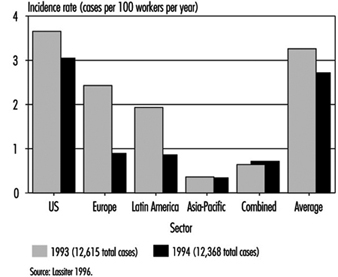
Figure 2. Distribution of incidence rates for Injuries and illnesses with days off from work by world sector 1993 and 1994
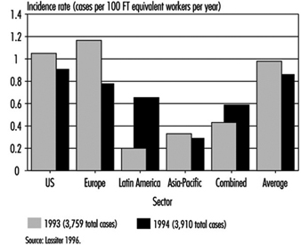
Figure 1 depicts work injury and illness incidence rates for the various world regions in the 1993-94 survey. Individual country rates have not been included to ensure confidentiality of those participating companies which were the sole sources of data for certain countries. Hence, for certain countries in the survey, data were reported for only a single facility. In several instances, companies combined all international data into a single statistic. These latter data are listed in figure 1 and figure 2 as “Combined”.
The annual incidence of work injuries and illnesses among all workers in the international survey was 3.3 cases per 100 employees (200,000 worker-hours) in 1993 and 2.7 in 1994. There were 12,615 cases reported for 1993 and 12,368 for 1994. The great majority of cases (12,130 in 1993) were derived from US companies. These cases were associated with approximately 387,000 workers in 1993 and 458,000 in 1994.
Figure 2 presents incidence rates for lost workday cases involving days away from work. The 1993 and 1994 incidence rates were based on approximately 4,000 lost workday cases for each of the 2 years in the international survey. The international/regional range in incidence rates for this statistic was the most narrow of those measured. The incidence of lost workday cases may represent the most comparable international statistics with respect to worker safety and health experience. The incidence rate for lost workdays (days away from work) was approximately 15.4 days away from work per 100 workers for each of the 2 years.
The only detailed data known to exist concerning case characteristics of semiconductor worker injuries and illnesses are those compiled annually in the US by the BLS, involving cases with lost workdays. The cases discussed here were identified by the BLS in their annual survey for the year 1993. Data obtained from these cases appear in figure 3, figure 4, figure 5 and figure 6. Each figure compares the lost workday case experience for the private sector, all manufacturing and semiconductor manufacturing.
Figure 3. Comparative incidence of lost workdays cases1 by type of event or exposure, 1993
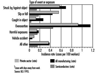
Figure 4. Comparative incidence of lost workday cases1 by source of injury or illness, 1993.
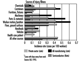
Figure 5. Comparative incidence of lost workday cases1 by nature of injury or illness, 1993.
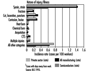
Figure 6. Comparative incidence of lost workday cases by part of body affected, 1993
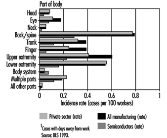
Figure 3 compares the lost workday case experience of US semiconductor workers in 1993 with the private sector and with all manufacturing with respect to type of event or exposure. The incidence rates for most categories in this figure were much less for semiconductor industry workers than for the private sector or all manufacturing. Cases involving overexertions among semiconductor workers were less than half the rate for all workers in the manufacturing sector. The harmful exposure category (primarily associated with exposures to chemical substances) was equivalent among all three groups.
Comparative distributions of lost workday cases according to source of injury or illness are presented in figure 4. Lost workday case incidence rates for semiconductor workers were less than those for the private sector and all manufacturing in all source categories except for cases associated with exposures to chemical substances.
Figure 5 compares lost workday case incidence rates associated with nature of injury or illness among the three groups. The rates for semiconductor workers were less than half of the rates for both the private sector and for all manufacturing in 1993. The incidence of chemical burns was slightly higher for semiconductor workers, but was very low for all three comparison groups. The incidence of carpal tunnel syndrome (CTS) among US semiconductor workers was less than half the rate for all manufacturing.
In figure 6, the distribution and incidence of cases involving days away from work is illustrated according to part of body affected. Although the incidence of cases involving body systems was low for all comparison groups, the rate for semiconductor workers was slightly elevated. All other body parts affected were much lower for semiconductor workers than for the other two comparison groups.
Epidemiological Studies of Semiconductor Workers
Concern for possible reproductive health consequences associated with employment in the semiconductor surfaced in 1983 when a female employee at the Digital Equipment Corporation’s semiconductor facility in Hudson, Massachusetts, indicated that she believed that an excess of miscarriages had occurred among employees in the facility’s cleanrooms. This allegation, coupled with an absence of internal data at the facility, led to an epidemiological study by the University of Massachusetts School of Public Health in Amherst (UMass). The study was begun in May of 1984 and completed in 1985 (Pastides et al. 1988).
An elevated risk of miscarriage was observed in both the photolithographic area and the diffusion area when compared to non-exposed workers in other areas of the facility. A relative risk of 1.75 was considered to be not statistically significant (p <0.05), although a 2.18 relative risk observed among workers in diffusion areas was significant. Publication of the UMass study led to concern throughout the semiconductor industry that a larger study was warranted to validate the observed findings and to determine their extent and possible causation.
The Semiconductor Industry Association (SIA) of the United States sponsored a larger study performed by the University of California at Davis (UC Davis) beginning in 1989. The UC Davis study was designed to test the hypothesis that semiconductor manufacturing was associated with an increased risk of miscarriage for female wafer fabrication employees. The study’s population was selected from among 14 companies which represented 42 production sites in 17 states. The highest number of sites (representing almost half of the employees in the study) was in California.
The UC Davis study consisted of three different components: a cross-sectional component (McCurdy et al. 1995; Pocekay et al. 1995); an historical cohort component (Schenker et al. 1995); and a prospective component (Eskenazi et al. 1995). Central to each of these studies was an exposure assessment (Hines et al. 1995; Hammond et al. 1995). The exposure assessment component assigned employees to a relative exposure group (i.e., high exposure, low exposure and so on).
In the historical component of the study, it was determined that the relative risk of fabrication workers, compared with non-fabrication workers, was 1.45 (i.e., 45% excess risk of miscarriage). The highest risk group identified in the historical component of the study were women who worked in photolithography or etching operations. Women performing etching operations experienced a relative risk of 2.15 (RR=2.15). In addition, a dose-response relationship was observed among women who worked with any photoresist or developer with respect to increased risk of miscarriage. These data supported a dose-response association for ethylene glycol ethers (EGE) but not for propylene glycol ethers (PGE).
Although an increased risk of miscarriage was observed among female wafer fabrication workers in the prospective component of the UC Davis study, the results were not statistically significant (p less than 0.05). A small number of pregnancies significantly reduced the power of the prospective component of the study. Analysis by exposure to chemical agent indicated an increased risk for those women who worked with ethylene glycol monoethyl ether, but was based on only 3 pregnancies. One important finding was the general support for, and not contradiction of, the findings of the historical component.
The cross-sectional component of the study noted an increase in upper respiratory symptoms primarily in the diffusion furnace and thin film groups of workers. An interesting finding was the apparent protective effects of various engineering controls related to ergonomics (e.g., footrests and the use of an adjustable chair to reduce back injuries).
Air measurements made in the wafer fabs found most solvent exposures were less than 1% of the permissible exposure limits (PEL) established by the US government.
A separate epidemiological study (Correa et al. 1996) was performed by the Johns Hopkins University (JHU), involving a group of IBM Corporation semiconductor employees in 1989. The overall miscarriage rate observed in the JHU study involving female cleanroom workers was 16.6%. The relative risk for miscarriage among female cleanroom workers with the highest potential exposure to ethylene glycol ethers was 2.8 (95% C.I. = 1.4-5.6).
Discussion of Reproductive Epidemiological Studies Involving Semiconductor Workers
The epidemiological studies were remarkable in the scope and similarity of results. These studies all produced similar findings. Each study documented an excess risk of spontaneous abortion (miscarriage) for female semiconductor wafer fabrication workers. Two of the studies (JHU and UC Davis) may indicate a causal association with exposures to ethylene-based glycol ethers. The UMass study found that the photo group (those exposed to glycol ether) had less risk than the diffusion group, which had no documented glycol ether exposure. While these studies indicate an increased risk of spontaneous abortions among wafer fabrication workers, the cause of such excess risk is unclear. The JHU study failed to document a significant role for glycol ethers, and the UC Davis study only marginally linked glycol ethers (through modelling of exposures and self-reported work practices) to reproductive effects. Little if any monitoring was performed in either study to determine exposures to glycol ethers. Following completion of these studies the semiconductor industry began switching from ethylene series glycol ethers to substitutes such as ethyl lactate and propylene series glycol ethers.
Conclusion
Based on the best available data concerning the annual incidence of work-related injuries and illnesses, semiconductor workers are at less risk than workers in other manufacturing sectors or throughout the private sector (including many non-manufacturing industries). On an international basis, it appears that work injury and illness statistical data associated with lost workday cases may be a fairly reliable indicator of the worldwide safety and health experience of semiconductor workers. The industry has sponsored several independent epidemiological studies in an attempt to find answers to questions of reproductive health consequences related to employment in the industry. Although a definitive association between observed miscarriages and exposures to ethylene-based glycol ethers was not established, the industry has begun to use alternative photoresist solvents.
Printed Circuit Board and Computer Assembly
Printed Wiring Boards
Printed wiring boards (PWBs) are the interconnective electrical framework and physical structure that hold together the various electronic components of a printed circuit board. The major categories of PWBs are single-sided, double-sided, multilayer and flexible. The complexity and spacing requirements of ever increasingly dense and smaller boards have required that both sides of the board be covered with underlying circuits. Single-sided boards met early calculator and simple consumer electronic devices requirements, but portable notebook computers, personal digital assistants and personal music systems have required double-sided and multilayer PWBs. The processing of the patterning of PWBs is essentially a photolithographic process that involves selectively depositing and removing layers of materials on a dielectric substrate that acts as the electrical “wiring” that is etched or deposited on the printed wiring board.
Multilayer boards contain two or more pieces of dielectric material with circuitry that are stacked up and bonded together. Electrical connections are established from one side to the other, and to the inner layer circuitry, by drilled holes which are subsequently plated through with copper. The dielectric substrate most commonly used is fibreglass sheets (epoxy/fibreglass laminate). Other materials are glass (with polyimide, Teflon or triazine resins) and paper covered with phenolic resin. In the United States, laminated boards are categorized based on their fire-extinguishing properties; drilling, punching and machining properties; properties of moisture absorption; chemical and heat resistance; and mechanical strength (Sober 1995). The FR-4 (epoxy resin and glass cloth substrate) is widely used for high-technology applications.
The actual PWB process involves numerous steps and a wide variety of chemical agents. Table 1 illustrates a typical multilayer process and the EHS issues associated with this process. The primary differences between a single-sided and double-sided board is that the single-sided starts with raw material clad only on one side with copper, and omits the electroless copper plating step. The standard double-sided board has a solder mask over bare copper and is plated through the holes; the board has gold-coated contacts and a component legend. The majority of PWBs are multilayer boards, which are double-sided with internal layers that have been fabricated and sandwiched inside the laminate package and then processed almost identically to a double-layer board.
Table 1. PWB process: Environmental, health and safety issues
|
Primary process steps |
Health and safety issues |
Environmental issues |
|
Material prep |
||
|
Purchase specific laminate, entry material and backup board in pre-cut size |
Computer aided design—VDU and ergonomics hazards |
None |
|
Stack and pin |
||
|
Copper-clad panels are stacked with entry material and backup board; holes drilled and |
Noise during drilling; drilling particulate containing copper, lead, gold and epoxy/fibreglass |
Waste particulate (copper, lead, gold and |
|
Drilling |
||
|
Numerically controlled (N/C) drilling machines |
Noise during drilling; drilling particulate containing copper, lead, gold and epoxy/fibreglass |
Waste particulate (copper, lead, gold and |
|
Deburr |
||
|
Drilled panels pass through brushes or abrasive wheel |
Noise during deburr; particulate containing copper, lead, gold and epoxy/fibreglass |
Waste particulate (copper, lead, gold and |
|
Electroless copper plating |
||
|
Adding thin copper layer to through holes |
Inhalation and dermal exposure to cleaners, conditioners, etchants, catalysts—H2SO4, H2O2, glycol ethers, KMnO4, NH4HF2, palladium, SnCl2, CuSO4, formaldehyde, NaOH |
Water effluents—acids, copper, caustics, |
|
Imaging |
||
|
Dry film resist—UV sensitive photopolymer |
Inhalation and dermal exposure to resists; developers; and |
Air emissions—solvents (VOCs), acid gases, |
|
Pattern plating |
||
|
Cleaning |
Inhalation and dermal hazards from cleaning; copper plating or tin/tin and lead plating and rack stripping—H3PO4, H2SO4; H2SO4 and CuSO4; fluoboric acid and Sn/Pb; concentrated HNO3 |
Air emissions—acid gases; water |
|
Strip, etch, strip |
||
|
Resist strip |
Inhalation and dermal hazards from resist strip; alkaline etch or copper strip—monoethanol amine (MEA); NH4OH; NH4Cl/NH4OH or NH4HF2 |
Air emissions—MEA, ammonia, fluorides; |
|
Solder mask |
||
|
Epoxy inks —screen printing |
Inhalation and dermal hazards from precleaning; epoxy inks and solvent carriers; developers—H2SO4; epichlorhydrin + bisphenol A, glycol ethers (PGMEA based); gamma-butyrolactone. UV light from curing process |
Air emissions—acid gases, glycol ethers |
|
Solder coating |
||
|
Solder levelling |
Inhalation and dermal hazards from flux, decomposition products and lead/tin solder residues—dilute glycol ethers + <1% HCl and <1% HBr; aldehydes, HCl, CO; lead and tin |
Air emissions—glycol ethers (VOC), acid gases, aldehydes, CO; waste—lead/tin solder, flux |
|
Gold and nickel plating |
||
|
Inhalation and dermal hazards from acids, metals and |
Air emissions—acid gases, cyanides; water |
|
|
Component legend |
||
|
Screen print |
Inhalation and dermal hazards from epoxy based inks and solvent carriers—glycol ether-based solvents, epichlorhydrin + bisphenol A |
Air emissions—glycol ethers (VOCs) waste — inks and solvents (small quantities) |
Cl2 = chlorine gas; CO = carboon monoxide; CuSO4 = copper sulphate; H2O2 = hydrogen peroxide;H2SO4 = sulphuric acid; H3PO4 = phosphoric acid; HBR = hydrobromic acid; HCl = hydrochloric acid; HNO3 = nitric acid; K2CO3 = potassium carbonate; KMNO4 = potassium permanganate; NA3PO4 = sodium phosphate; NH4Cl = ammonium chloride; NH4OH = ammonium hydroxide; NiSO4 = nickel sulphate; Pb = lead; Sn = tin; SnCl2 = stannous chloride; UV = ultraviolet; VOCs = volatile organic compounds.
Printed Circuit Board Assembly
Printed circuit board (PCB) assembly involves the hard attachment of electronic components to the PWB through the use of lead/tin solder (in a wave solder machine or applied as a paste and then reflowed in a low-temperature furnace) or epoxy resins (cured in a low-temperature furnace). The underlying PWB (single-sided, double-sided, multilayer or flexible) will determine the densities of components that can be attached. Numerous process and reliability issues form the basis for the selection of the PCB assembly processes that will be utilized. The major technological processes are: total surface mounting technology (SMT), mixed technology (includes both SMT and plated through hole (PTH)) and underside attachment.
Typically in modern electronics/computer assembly facilities, the mixed technology is utilized, with some components being surface mounted and other connectors/components being soldered on using through-hole technology or solder reflowing. A “typical” mixed technology process is discussed below, wherein a surface mount process involving adhesive attach, wave soldering and reflow soldering is utilized. With mixed technology, it is sometimes possible to reflow surface mount components (SMCs) on the top side of a double-sided board and wave solder the SMCs on the underside. Such a process is particularly useful when the surface mount and through-hole technologies must be mixed on a single board, which is the norm in current electronics manufacturing. The first step is to mount the SMCs to the top side of the board, using the solder reflow process. Next, the through-hole components are inserted. The board is then inverted, and the underside SMCs are mounted adhesively to the board. Wave soldering of both through-hole components and underside SMCs is the final step.
The major technical mixed technology process steps include:
- pre- and post-cleaning
- solder paste and adhesive application (screen print and placement (SMT and PTH))
- component insertion
- adhesive cure and solder reflow
- fluxing (PTH)
- wave soldering (PTH)
- inspection and touch-up
- testing
- reworking and repairing
- support operations—stencil cleaning.
A brief discussion of the important environmental, health and safety implications for each process step is provided below.
Pre- and post-cleaning
Commercial PWBs are typically purchased from a PWB supplier and have been pre-cleaned with de-ionized (DI) water solution to remove all surface contaminants. Prior to the concerns regarding stratospheric ozone layer depletion, an ozone depleting substance, such as a chlorofluorocarbon (CFC), would be used as a final clean, or even pre-clean by the electronic device manufacturer. At the end of the PCB assembly process, the use of a chlorofluorocarbon “vapour degreasing” operation to remove residues from the flux/wave soldering operation was typical. Again due to concerns about ozone depletion and tight regulatory controls on the production of CFCs, process changes were made that allowed the complete PWB assemblies to by-pass cleaning or use only a DI water cleaning.
Solder paste and adhesive application (stencil print and placement) and component insertion
The application of lead/tin solder paste to the PWB surface allows the surface mount component to be attached to the PWB and is key to the SMT process. The solder material acts as a mechanical linkage for electrical and thermal conduction and as a coating for surface protection and enhanced solderability. The solder paste is made up of approximately 70 to 90% non-volatile matter (on a weight per weight or weight per volume basis):
- lead/tin solder
- a blend of modified resins (rosin acids or mildly activated rosin)
- activators (in the case of “no clean” products, mixtures of amine hydrohalides and acids or just carboxylic acids).
Solvents (volatile matter) make-up the remainder of the product (typically an alcohol and glycol ether mixture that is a proprietary blend).
The solder paste is printed through a stencil, which is an exact pattern of the surface design that is to be added to the PWB surface. The solder paste is pushed through the apertures in the stencil onto the pad sites on the PWB by means of a squeegee that slowly traverses the stencil. The stencil is then lifted away, leaving the paste deposits on the appropriate pads on the board. The components are then inserted on the PWB. The primary EHS hazards relate to the housekeeping and personal hygiene of the operators that apply the solder paste to the stencil surface, clean the squeegee and clean the stencils. The concentration of lead in the solder and the tendency of the dried solder paste to adhere to the skin and equipment/facility work surfaces requires the use of protective gloves, good clean-up of work surfaces, safe disposal of contaminated clean-up materials (and environmental handling) and strict personal hygiene by the operators (e.g., handwashing with soap prior to eating, drinking or applying cosmetics). Airborne exposure levels are typically below the detection limit for lead, and if good housekeeping/personal hygiene is used, blood lead readings are at background levels.
The adhesive application involves the automated dispensing of small quantities of an epoxy resin (typically a bisphenol A-epichlorhydrin mixture) onto the PWB surface and then “picking and placing” the component and inserting it through the epoxy resin onto the PWB. The EHS hazards primarily relate to the mechanical safety hazards of the “pick and place” units, due to their automated mechanical assemblies, component shuttles on the rear of the units and potential for serious injury if appropriate guarding, light curtains and hardware interlocks are not present.
Adhesive cure and solder reflow
The components that were attached by stencil printing or adhesive application are then carried on a fixed-height mechanical conveyor to an in-line reflow furnace that “sets off” the solder by reflowing the solder paste at approximately 200 to 400°C. The components that were attached by the epoxy adhesive are also run through a furnace that is downline of the solder reflow and is typically run at 130 to 160oC. The solvent components of the solder paste and epoxy resin are driven off during the furnace process, but the lead/tin component is not volatilized. A spider-web type residue will build up in the exhaust duct of the reflow furnace, and a metal mesh filter can be used to prevent this. PWBs can occasionally get caught in the conveyor system and will overheat in the furnace, causing objectionable odours.
Fluxing
To form a reliable solder joint at the PWB surface and the component lead, both must be free of oxidation and must remain so even at the elevated temperatures used in soldering. Also, the molten solder alloy must wet the surfaces of the metals to be joined. This means the solder flux must react with and remove metal oxides from the surfaces to be joined and prevent the re-oxidation of the cleaned surfaces. It also requires that the residues be either non-corrosive or easily removable. Fluxes for soldering electronic equipment fall into three broad categories, commonly known as rosin-based fluxes, organic or water-soluble fluxes and solvent-removable synthetic fluxes. Newer, low-solids “no clean” or non-volatile organic compound (NVOC) fluxes fall into the middle category.
Rosin-based fluxes
The rosin-based fluxes are the most commonly used fluxes in the electronics industry, either as spray flux or foam flux. The fluxer may be contained either internal to the wave soldering equipment or as a stand-alone unit positioned at the infeed to the unit. As a base, rosin-based fluxes have natural rosin, or colophony, the translucent, amber-coloured rosin obtained after turpentine has been distilled from the oleoresin and canal resin of pine trees. The resin is collected, heated and distilled, which removes any solid particles, resulting in a purified form of the natural product. It is a homogeneous material with a single melting point.
Colophony is a mixture of approximately 90% resin acid, which is mostly abietic acid (a non-water soluble, organic acid) with 10% neutral materials such as stilbene derivatives and various hydrocarbons. Figure 1 provides the chemical structures for abietic and pimaric acids.
Figure 1. Abietic & pimaric acids
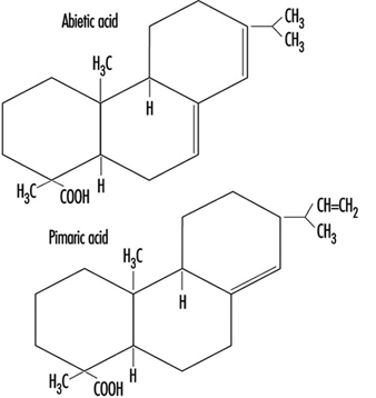
The active constituent is abietic acid, which at soldering temperature is chemically active and attacks the copper oxide on the PWB surface, forming copper abiet. Rosin-based fluxes have three components: the solvent or vehicle, the rosin and the activator. The solvent simply acts as a vehicle for the flux. To be effective the rosin must be applied to the board in a liquid state. This is accomplished by dissolving the rosin and activator in a solvent system, typically isopropyl alcohol (IPA) or multicomponent mixtures of alcohols (IPA, methanol or ethanol). Then the flux is either foamed onto the bottom surface of the PCB through the addition of air or nitrogen, or sprayed in a “low-solids” mixture which has a higher solvent content. These solvent components have different evaporation rates, and a thinner must be added to the flux mixture to maintain a constituent flux composition. The primary categories of rosin-based fluxes are: rosin mildly active (RMA), which are the typical fluxes in use, to which a mild activator is added; and rosin active (RA), to which a more aggressive activator has been added.
The primary EHS hazard of all the rosin-based fluxes is the alcohol solvent base. Safety hazards relate to flammability in storage and use, classification and handling as a hazardous waste, air emissions and treatment systems required to remove the VOCs and industrial hygiene issues related to inhalation and skin (dermal) exposure. Each of these items requires a different control strategy, employee education and training and permits/regulatory compliance (Association of the Electronics, Telecommunications and Business Equipment Industries 1991).
During the wave soldering process, the flux is heated to 183 to 399°C; airborne products generated include aliphatic aldehydes, such as formaldehyde. Many fluxes also contain an organic amine hydrochloride activator, which helps clean the area being soldered and releases hydrochloric acid when heated. Other gaseous components include benzene, toluene, styrene, phenol, chlorophenol and isopropyl alcohol. In addition to the gaseous components of heated flux, a significant amount of particulates are created, ranging in size from 0.01 micron to 1.0 micron, known as colophony fumes. These particulate materials have been found to be respiratory irritants and also respiratory sensitizers in sensitive individuals (Hausen, Krohn and Budianto 1990). In the United Kingdom, airborne exposure standards require that colophony fume levels be controlled to the lowest levels attainable (Health and Safety Commission 1992). Additionally, the American Conference of Governmental Industrial Hygienists (ACGIH) has established a separate threshold limit value for the pyrolysis products of rosin core solder of 0.1 mg/m3, measured as formaldehyde (ACGIH 1994). The Lead Industries Association, Inc. identifies acetone, methyl alcohol, aliphatic aldehydes (measured as formaldehyde), carbon dioxide, carbon monoxide, methane, ethane, abietic acid and related diterpene acids as typical decomposition products of rosin core soldering (Lead Industries Association 1990).
Organic fluxes
Organic fluxes, sometimes called intermediate fluxes or water-soluble fluxes, are composites that are more active than the rosin-based fluxes and less corrosive than acid fluxes used in the metal-working industries. The general active compounds of this class of fluxes fall into three groups:
- acids (e.g., stearic, glutamic, lactic, citric)
- halogens (e.g., hydrochlorides, bromides, hydrazine)
- amides and amines (e.g., urea, triethanolamine).
These materials and other parts of the formulation, such as surfactants to assist in reducing the solder surface tension, are dissolved in polyethylene glycol, organic solvents, water or usually a mixture of several of these. Organic fluxes must be considered corrosive, but can be cleaned off easily, with no more than hot water.
Synthetic activated (AS) fluxes
Whereas rosin-based fluxes are solid materials dissolved in a solvent, AS fluxes are usually totally liquid formulas (solvent + flux). The solvent carrier is driven off during the preheating phase of wave soldering, leaving a wet and oily residue on the PWB surface, which must be cleaned off immediately following soldering. The primary attribute of AS fluxes is their ability to be removed by the use of a suitable solvent, typically fluorocarbon based. With restrictions on the use of ozone-depleting substances such as fluorocarbons (Freon TF, Freon TMS and so on), the required use of these cleaning materials has severely restricted the use of this class of fluxes.
Low-solids “no clean” or non-VOC fluxes
The need for the elimination of the post-soldering cleaning of corrosive or tacky flux residues with fluorocarbon solvents has lead to the widespread usage of a new class of fluxes. These fluxes are similar in activity to the RMA fluxes and have a solids content of approximately 15%. The solids content is a measure of viscosity and equals the ratio of flux to solvent. The lower the solids contents, the higher the percentage of solvent. The higher the solids content, the more active the flux, and the more potential for needing a post-soldering cleaning step. Low-solids flux (LSF) is commonly used in the electronics industry and typically does not require the post-cleaning step. From an environmental air-emission perspective, the LSF eliminated the need for fluorocarbon vapour degreasing of wave soldered boards, but with their higher solvent content, they increased the quantity of alcohol-based solvents evaporated, resulting in higher VOC levels. VOC air-emission levels are tightly controlled in the United States, and in many locations worldwide. This situation was addressed by the introduction of “no clean” fluxes, which are water based (rather than solvent based) but contain similar activators and fluxing rosins. The primary active ingredients are dicarboxylic acid based (2 to 3%), typically glutaric, succinic and adipic acids. Surfactants and corrosion inhibitors (approximately 1%) are also included, resulting in a pH (acidity) of 3.0 to 3.5. These fluxes virtually eliminate VOC air emissions and other EHS hazards associated with using solvent-based fluxes. The decomposition products noted in rosin-based fluxes are still applicable, and the mild pH does require that the flux-handling equipment be acid resistant. Some anecdotal evidence points to potential dermal or respiratory problems from the dried, mildly acidic dicarboxylic acids and corrosion inhibitors that may become a residue on board carriers, carts and internal surfaces of wave soldering equipment utilizing these compounds. Also, the water component of these fluxes may not get adequately evaporated prior to hitting the molten solder pot, which can lead to splattering of the hot solder.
Wave soldering
The addition of flux to the bottom surface of the PWB can be accomplished either by a fluxer located internal to the wave soldering unit or a stand-alone unit at the entry to the wave soldering unit. Figure 2 provides a schematic representation of a standard wave soldering unit with the fluxer located internally. Either configuration is used to foam or spray the flux onto the PWB.
Figure 2. Wave solder unit schematic
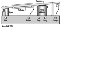
Preheating
The flux carriers must be evaporated prior to soldering. This is accomplished by using high-temperature preheaters to drive off the liquid components. Two basic types of preheaters are in use: radiant (hot rod) and volumetric (hot air). The radiant heaters are common in the United States and present the potential for ignition of excess flux or solvent or the decomposition of a PWB should it become immobilized under the preheater. Local exhaust ventilation is provided on the fluxer/preheater side of the wave soldering unit to capture and exhaust the solvent/flux materials evaporated during these operations.
Soldering
The solder alloy (typically 63% tin to 37% lead) is contained in a large reservoir called the solder pot, and is heated electrically to maintain the solder in a molten state. The heaters include a powerful bulk heater to do the initial melt and a smaller regulated heat supply to control the temperature thermostatically.
Successful board-level soldering requires that the design of the solder pot and recirculation pump systems continually provide a consistent “wave” of fresh solder. With soldering, the pure solder becomes contaminated with oxidized lead/tin compounds, metallic impurities and flux decomposition products. This dross forms on the surface of the molten solder, and the more dross formed, the more of a tendency for additional formation. Dross is harmful to the soldering process and the solder wave. If enough forms in the pot, it can get pulled into the recirculation pump and cause impeller abrasion. Wave solder operators are required to de-dross the wave on a routine basis. This process involves the operator straining the solidified dross from the molten solder and collecting the residues for reclaim/recycling. The process of de-drossing involves the operator physically opening up the rear access door (typically a gulf-wing configuration) adjacent to the solder pot and manually scooping out the hot dross. During this process, visible emissions are liberated from the pot which are highly irritating to the eyes, nose and throat of the operator. The operator is required to wear thermal gloves, an apron, safety glasses and a face shield and respiratory protection (for lead/tin particulate, corrosive gases (HCl) and aliphatic aldehyde (formaldehyde)). Local exhaust ventilation is provided from the interior of the wave soldering unit, but the solder pot is mechanically withdrawn from the main cabinet to allow the operator direct access to both sides of the hot pot. Once withdrawn, the local exhaust duct that is mounted in the cabinet becomes ineffective for removing the liberated materials. The primary health and safety hazards are: thermal burns from hot solder, respiratory exposure to materials noted above, back injuries from handling heavy solder ingots and dross drums and exposure to lead/tin solder residues/fine particulate during maintenance activities.
During the actual soldering process, the access doors are closed and the interior of the wave soldering unit is under a negative pressure due to the local exhaust ventilation provided on the flux and solder pot sides of the wave. This ventilation and the operating temperatures of the solder pot (typically 302 to 316°C, which is just above the melting point of solder), result in the minimal formation of lead fumes. The primary exposure to lead/tin particulate comes during the de-drossing and equipment maintenance activities, from the agitation of the dross in the pot, transfer to the reclaim vessel and clean-up of solder residues. Fine lead/tin particulate is formed during the de-drossing operation and can be released into the workroom and breathing zone of the wave solder operator. Various engineering control strategies have been devised to minimize these potential lead particulate exposures, including the incorporation of local exhaust ventilation to the reclaim vessel (see figure 3), use of HEPA vacuums for residue clean-up and flexible exhaust ducts with articulating arms to position ventilation at the hot pot during de-drossing. The use of brooms or brushes for sweeping up solder residues must be prohibited. Stringent housekeeping and personal hygiene practices must also be required. During wave solder equipment maintenance operations (which are done on a weekly, monthly, quarterly and annual basis), various components of the hot pot are either cleaned within the equipment or removed and cleaned in a locally exhausted hood. These cleaning operations may involve physically scraping or mechanically cleaning (using an electric drill and wire brush attachment) the solder pump and baffles. High levels of lead particulate are generated during the mechanical cleaning process, and the process should be performed in a locally exhausted enclosure.
Figure 3. Dross cart with vacuum cover
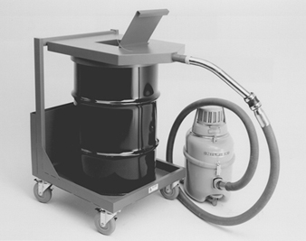
Inspection, touch-up and testing
Visual inspection and touch-up functions are conducted after wave soldering and involve the use of magnifying lenses/task lights for fine inspection and touch-up of imperfections. The touch-up function may involve the use of a stick-solder hand-held soldering iron and rosin core solder or brushing on a small amount of liquid flux and lead/tin wire solder. The visual fumes from the stick soldering involve breakdown products from the flux. Small quantities of lead/tin solder bead that did not adhere to the solder joint may present a housekeeping and personal hygiene issue. Either a fan adjacent to the workstation for general dilution ventilation away from the operator’s breathing zone or a more sophisticated fume exhaust system that captures the breakdown products at the tip of the soldering iron or adjacent to the operation should be provided. The fumes are then routed to an air scrubber exhaust system that incorporates HEPA filtration for particulates and activated carbon gas adsorption for the aliphatic aldehydes and hydrochloric acid gases. The effectiveness of these soldering exhaust systems is highly dependent on capture velocities, proximity to the point of fume generation and lack of cross drafts at the work surface. The electrical testing of the completed PCB requires specialized test equipment and software.
Reworking and repairing
Based on the results of the board testing, defective boards are evaluated for specific component failures and replaced. This reworking of the boards may involve stick soldering. If primary components on the PCB such as the microprocessor need replacement, a rework solder pot is used for immersing that portion of the board housing the defective component or joint in a small solder pot, removing the component and then inserting a new functional component back onto the board. If the component is smaller or more easily removed, an air vac system that uses hot air for heating the solder joint and vacuum for removing the solder is employed. The rework solder pot is housed within a locally exhausted enclosure that provides sufficient exhaust velocity to capture the flux decomposition products formed when the liquid solder is brushed on the board and solder contact made. This pot also forms dross and requires de-drossing equipment and procedures (on a much smaller scale). The air vac system does not require being housed within an enclosure, but the lead/tin solder removed must be handled as a hazardous waste and reclaimed/recycled.
Support operations—stencil cleaning
The first step in the PCB assembly process involved the use of a stencil for providing the pattern of bonding locations for the lead/tin solder paste to be squeegeed through. Typically, the stencil’s openings start to become clogged and the lead/tin solder paste residues must be removed on a per shift basis. A pre-cleaning is usually performed at the screen printer to capture gross contamination on the board, by wiping the board surface with a dilute alcohol mixture and disposable wipes. To completely remove the remaining residues a wet-cleaning process is required. In a system similar to a large dishwasher, hot water (57°C) and a chemical solution of dilute aliphatic amines (monoethanol amine) is used to chemically remove the solder paste from the stencil. Significant quantities of lead/tin solder are washed off the board and either deposited in the wash chamber or in solution in the water effluent. This effluent requires filtration or chemical removal of lead and pH adjustment for the corrosive aliphatic amines (using hydrochloric acid). Newer closed system stencil cleaners utilize the same wash solution until it is spent. The solution is transferred to a distillation unit, and the volatiles are distilled off until a semi-liquid residue is formed. This residue is then handled as a lead/tin-contaminated hazardous waste.
Computer Assembly Process
Once the final PCB is assembled, it is transferred to the systems assembly operation for incorporation into the final computer product. This operation is typically very labour intensive, with the component parts to be assembled supplied to the individual workstations on staging carts along the mechanized assembly line. The major health and safety hazards relate to materials movement and staging (fork-lifts, manual lifting), ergonomic implications of the assembly process (range of motion, insertion force required to “set” components, installation of screws and connectors) and final packaging, shrink wrapping and shipping. A typical computer assembly process involves:
- chassis/case preparation
- PCB (mother and daughter board) insertion
- primary component (floppy drive, hard drive, power supply, CD-ROM drive) insertion
- display assembly (portables only)
- mouse and keyboard insertion (portables only)
- cabling, connectors and speakers
- top cover assembly
- software downloading
- test
- rework
- battery charging (portables only) and packaging
- shrink wrapping and shipping.
The only chemicals that may be used in the assembly process involve the final cleaning of the computer case or monitor. Typically, a dilute solution of isopropyl alcohol and water or a commercial mixture of cleaners (e.g., Simple Green—a dilute butyl cellosolve and water solution) is used.
III-V Semiconductor Manufacturing
Silicon has historically dominated IC technology development as the primary semiconductor material. The principal focus in recent years on a silicon alternative has concentrated on III-V compounds, such as gallium arsenide (GaAs), as a substrate material. As a semiconductor material, GaAs exhibits increased capabilities over silicon, such as electron mobility 5 to 6 times that of silicon. This characteristic, coupled with the potential semi- insulating properties of GaAs, leads to increased performance in both speed and power consumption.
GaAs has a zinc blende-structure consisting of two interpenetrating face-centred cubic sublattices which relate to the growth of high quality ingot material. The technology involved in the growth of GaAs is considerably more complicated than that employed for silicon, as a more complicated two-phase equilibrium and a highly volatile component, arsenic (As), is involved. Precise control of the As vapour pressure in the ingot growth system is required to maintain exact stoichiometry of the GaAs compound during the growth process. Two primary categories of III-V semiconductor display and device production have economically feasible processing procedures—LED displays and microwave IC devices.
LEDs are fabricated from single-crystal GaAs in which p-n junctions are formed by the addition of suitable doping agents—typically tellurium, zinc or silicon. Epitaxial layers of ternary and quaternary III-V materials such as gallium arsenide phosphide (GaAsP) are grown on the substrate and result in an emission band of specific wavelengths in the visible spectrum for displays or in the infrared spectrum for emitters or detectors. For example, red light with a peak at about 650 nm comes from the direct recombination of the p-n electrons and holes. Green-emitting diodes are generally composed of gallium phosphide (GaP). The generalized LED processing steps are covered in this article.
Microwave IC devices are a specialized form of integrated circuit; they are used as high-frequency amplifiers (2 to 18 GHz) for radar, telecommunications and telemetry, as well as for octave and multi-octave amplifiers for use in electronic warfare systems. Microwave IC device manufacturers typically purchase single-crystal GaAs substrate, either with or without an epitaxial layer, from outside vendors (as do silicon device manufacturers). The major processing steps include liquid-phase epitaxial deposition, fabrication and non-fabrication processing similar to silicon device manufacturing. Processing steps which warrant description additional to that for LED processing are also discussed in this article.
Wafer Manufacturing
Similar to the silicon ingot growth process, elemental forms of gallium and arsenic, plus small quantities of dopant material—silicon, tellurium or zinc—are reacted at elevated temperatures to form ingots of doped single-crystal GaAs. Three generalized methods of ingot production are utilized:
- horizontal or vertical Bridgeman
- horizontal or vertical gradient freeze
- high- or low-pressure liquid encapsulated Czochralski (LEC).
The bulk polycrystalline GaAs compound is normally formed by the reaction of As vapour with Ga metal at elevated temperatures in sealed quartz ampoules. Typically, an As reservoir located at one end of the ampoule is heated to 618°C. This generates approximately 1 atmosphere of As vapour pressure in the ampoule, a prerequisite for obtaining stoichiometric GaAs. The As vapour reacts with the Ga metal maintained at 1,238°C and located at the other end of the ampoule in a quartz or pyrolytic boron nitride (PBN) boat. After the arsenic has been completely reacted, a polycrystalline charge is formed. This is used for single-crystal growth by programmed cooling (gradient freeze) or by physically moving either the ampoule or furnace to provide proper temperature gradients for growth (Bridgeman). This indirect approach (arsenic transport) for compounding and growth of GaAs is used because of the high vapour pressure of arsenic at the melting point of GaAs, about 20 atmospheres at 812°C and 60 atmospheres at 1,238°C, respectively.
Another approach to the commercial production of bulk single-crystal GaAs is the LEC technique. A Czochralski crystal puller is loaded with chunk GaAs in a crucible with an outer graphite susceptor. The bulk GaAs is then melted at temperatures close to 1,238°C, and the crystal is pulled in a pressurized atmosphere which could vary by manufacturer typically from a few atmospheres up to 100 atmospheres. The melt is completely encapsulated by a viscous glass, B2O3, which prevents melt dissociation as the As vapour pressure is matched or exceeded by the pressure of an inert gas (typically argon, or nitrogen) applied in the puller chamber. Alternatively, monocrystalline GaAs can be synthesized in situ by injecting the As into the molten Ga or combining As and Ga directly at high pressure.
GaAs wafer manufacturing represents the semiconductor manufacturing process with the greatest potential for significant, routine chemical exposures. While GaAs wafer manufacturing is done only by a small percentage of semiconductor manufacturers, particular emphasis is needed in this area. The large amounts of As used in the process, the numerous steps in the process and the low airborne exposure limit for arsenic make it difficult to control exposures. Articles by Harrison (1986); Lenihan, Sheehy and Jones (1989); McIntyre and Sherin (1989) and Sheehy and Jones (1993) provide additional information on the hazards and controls for this process.
Polycrystalline ingot synthesis
Ampoule load and seal
Elemental As (99.9999%) in chunk form is weighed and loaded into a quartz boat in an exhausted glove box. Pure liquid Ga (99.9999%) and the dopant material are also weighed and loaded into a quartz or pyrolytic boron nitride (PBN) boat(s) in the same manner. The boats are loaded into a long cylindrical quartz ampoule. (In the Bridgman and gradient freeze techniques, a seed crystal with the desired crystallographic orientation is also introduced, whereas in the two-stage LEC technique, where only poly GaAs is needed at this stage, a polycrystalline GaAs is synthesized without the seed crystal.)
The quartz ampoules are placed in a low-temperature furnace and heated while the ampoule is purged with hydrogen (H2), in a process known as hydrogen reduction reaction, to remove oxides. After purging with an inert gas such as argon, the quartz ampoules are attached to a vacuum pump assembly, evacuated, and the ampoule ends are heated and sealed with a hydrogen/oxygen torch. This creates a charged and sealed quartz ampoule ready for furnace growth. Hydrogen purging and the hydrogen/oxygen torch system is a potential fire/explosion hazard if proper safety devices and equipment are not in use (Wade et al. 1981).
Because the arsenic is being heated, this assembly is maintained under exhaust ventilation. Arsenic oxide deposits can form in the exhaust duct supporting this assembly. Care must be taken to prevent exposure and contamination should the ducts be disturbed in any way.
Storage and handling of arsenic chunks is a concern. For security, often the arsenic is kept under locked storage and with a tight inventory control. Typically the arsenic is also kept in a fire-rated storage cabinet to prevent its involvement in event of a fire.
Furnace growth
The Bridgeman and the gradient freeze methods of single-crystal ingot growth both utilize charged and sealed quartz ampoules in a high-temperature furnace enclosure which is vented to a wet scrubber system. The primary exposure hazards during furnace growth relate to the potential for the quartz ampoule to implode or explode during ingot growth. This situation occurs on a rather sporadic and infrequent basis, and is the result of one of the following:
- the partial pressure of the As vapour which results from the high temperatures used in the growth process
- devitrification of the quartz ampoule glass, which creates hairline cracks and the attendant potential for de-pressurization of the ampoule
- lack of accurate high-temperature control devices on the heating source—usually resistance type—with the resultant over-pressurization of the quartz ampoule
- thermocouple malfunction or failure, resulting in over-pressurization of the quartz ampoule
- excess As or too little Ga in the ampoule tube, resulting in extremely high As pressure, which can cause catastrophic depressurization of the ampoule.
The horizontal Bridgeman system consists of a multizone furnace in which the sealed quartz ampoule has separate temperature zones—the arsenic “cold” finger end at 618°C and the quartz gallium/dopant/seed crystal boat containing the melt at 1,238°C. The basic principle in the horizontal Bridgeman system involves traversing two heated zones (one above the melting point of GaAs, and one below the melting point) over a boat of GaAs to provide the precisely controlled freezing of molten GaAs. The seed crystal, maintained at all times in the freeze zone, provides the initial crystal starting structure, defining the direction and orientation of the crystalline structure within the boat. The quartz boat and ampoule of Ga and As are suspended within the heater chamber by a set of silicon carbide liners called support tubes, which are positioned within the resistance heater assembly to mechanically move the full distance of the ampoule. Additionally, the furnace assembly rests on a table which must be tilted during growth to provide the proper interface of the synthesized GaAs melt with the seed crystal.
In the gradient freeze method, a multizone high temperature furnace utilizing resistance heating is kept at 1,200 to 1,300 °C (1,237°C is the melt/freeze point of GaAs). The total ingot growth process duration is typically 3 days and comprises the following steps:
- furnace firing to temperature
- GaAs synthesis
- seeding the melt
- cool down/crystal growth.
The quartz ampoule is also tilted during the growth process by the use of a scissors-type manual jack.
Ampoule breakout
After the single-crystal GaAs ingot is grown within the sealed quartz ampoule, the ampoule must be opened and the quartz boat containing the ingot plus seed crystal removed. This is accomplished by one of the following methods:
- cutting off the sealed end of the ampoules with a wet circular saw
- heating and cracking the ampoule with a hydrogen/oxygen torch
- breaking the bagged ampoule with a hammer while under exhaust to control the airborne arsenic.
The quartz ampoules are recycled by wet etching the condensed arsenic on the interior surface with aqua regia (HCl,HNO3) or sulphuric acid/hydrogen peroxide (H2SO4/H2O2).
Ingot beadblasting/cleaning
In order to see polycrystalline defects and remove exterior oxides and contaminants, the single-crystal GaAs ingot must be beadblasted. The beadblasting is done in an exhausted glove-box unit utilizing either silicon carbide or calcined alumina blasting media. Wet cleaning is done in chemical baths provided with local exhaust ventilation and utilizing aqua regia or alcohol rinses (isopropyl alcohol and/or methanol).
Monocrystalline ingot growth
The polycrystalline GaAs ingot retrieved from the ampoule is broken into chunks, weighed and placed into a quartz or PBN crucible, and a boron oxide disc is placed on top of it. The crucible is then placed into a crystal grower (puller) pressurized in an inert gas, and heated to 1,238°C. At this temperature, the GaAs melts, with the lighter boron oxide becoming a liquid encapsulant to prevent the arsenic from dissociating from the melt. A seed crystal is introduced into the melt below the liquid cap and while counter-rotating, is slowly withdrawn from the melt, thereby solidifying as it leaves the “hot-zone”. This process takes approximately 24 hours, depending on the charge size and crystal diameter.
Once the growth cycle is completed, the grower is opened to retrieve the monocrystalline ingot and for cleaning. Some amount of arsenic escapes from the melt even with the liquid cap in place. There can be significant exposure to airborne arsenic during this step of the process. To control this exposure, the grower is cooled to below 100°C, which results in the deposition of fine arsenic particulate on the interior surface of the grower. This cooling helps minimize the amount of arsenic that becomes airborne.
Heavy deposits of arsenic-containing residues are left on the inside of the crystal grower. Removal of the residues during routine preventive maintenance can result in significant airborne concentrations of arsenic (Lenihan, Sheehy and Jones 1989; Baldwin and Stewart 1989; McIntyre and Sherin 1989). Controls used during this maintenance operation often include scavenger exhaust ventilation, disposable clothing and respirators.
When the ingot is removed, the grower is dismantled. A HEPA vacuum is utilized to pick up arsenic particulates on all parts of the grower. After vacuuming, the stainless steel parts are wiped with an ammonium hydroxide/hydrogen peroxide mixture to remove any residual arsenic, and the grower is assembled.
Wafer processing
X-ray diffraction
The crystalline orientation of the GaAs ingot is determined by the use of an x-ray diffraction unit, as in silicon ingot processing. A low-powered laser can be used to determine the crystalline orientation in a production setting; however, x-ray diffraction is more accurate and is the preferred method.
When x-ray diffraction is used, often the x-ray beam is totally enclosed in a protective cabinet that is periodically checked for radiation leakage. Under certain circumstances, it is not practical to fully contain the x-ray beam in an interlocked enclosure. In this instance operators may be required to wear radiation finger badges, and controls similar to those used for high-powered lasers are used (e.g., enclosed room with limited access, operator training, enclosing the beam as much as practical, etc.) (Baldwin and Williams 1996).
Ingot cropping, grinding and slicing
The ends or tails of the single-crystal ingot are removed, using a water-lubricated single-bladed diamond saw, with various coolants added to the water. The monocrystalline ingot is then placed on a lathe which shapes it into a cylindrical ingot of uniform diameter. This is the grinding process, which is also a wet process.
After cropping and grinding, GaAs ingots are epoxy or wax mounted to a graphite beam and sawed into individual wafers through the use of automatically operated inside diameter (ID) diamond-blade saws. This wet operation is done with the use of lubricants and generates a GaAs slurry, which is collected, centrifuged and treated with calcium fluoride to precipitate out the arsenic. The supernatant is tested to ensure that it does not contain excess arsenic, and the sludge is pressed into a cake and disposed of as hazardous waste. Some manufacturers send the collected slurry from the ingot cropping, grinding and slicing processes for Ga reclaim.
Arsine and phosphine may be formed from the reaction of GaAs and indium phosphide with moisture in the air, other arsenides and phosphides or when mixed with acids during the processing of gallium arsenide and indium phosphide; 92 ppb arsine and 176 ppb phosphine have been measured 2 inches away from the slicing blades used to cut GaAs and indium phosphide ingots (Mosovsky et al. 1992, Rainer et al. 1993).
Wafer washing
After GaAs wafers are dismounted from the graphite beam, they are cleaned by sequential dipping in wet chemical baths containing solutions of sulphuric acid/hydrogen peroxide or acetic acid and alcohols.
Edge profiling
Edge profiling is also a wet process performed on sliced wafers to form an edge around the wafer, which makes it less prone to breakage. Because only a thin cut is made on the surface of the wafer, only a small amount of slurry is generated.
Lapping and polishing
Wafers are wax mounted on a lapping or grinding plate, using a hotplate, and are lapped on a machine exerting a set rotational speed and pressure. A lapping solution is fed onto the lapping surface (a slurry of aluminium oxide, glycerine and water). After a brief lapping period, when the desired thickness is achieved, the wafers are rinsed and mounted on a mechanical polishing machine. Polishing is performed using a sodium bicarbonate, 5% chlorine, water (or sodium hypochlorite) and colloidal silica slurry. The wafers are then dismounted on a hotplate, the wax is removed using solvents and the wafers are cleaned.
Epitaxy
The single-crystal GaAs wafers are used as substrates for the growth of very thin layers of the same or other III-V compounds having the desired electronic or optical properties. This must be done in such a way as to continue, in the grown layer, the crystal structure of the substrate. Such crystal growth, in which the substrate determines the crystallinity and orientation of the grown layer, is called epitaxy, and a variety of epitaxial growth techniques are used in III-V display and device production. The most common techniques are:
- liquid-phase epitaxy (LPE)
- molecular-beam epitaxy (MBE)
- vapour-phase epitaxy (VPE)
- metallorganic chemical-vapour deposition (MOCVD)—also known as organometallic vapour-phase epitaxy (OMVPE).
Liquid-phase epitaxy
In LPE a layer of doped III-V material is grown directly on the surface of the GaAs substrate using a graphite holder that contains separate chambers for the material to be deposited on the wafers. Weighed quantities of deposition materials are added to the upper chamber of the holder, while the wafers are placed in a lower chamber. The assembly is placed within a quartz reaction tube under a hydrogen atmosphere. The tube is heated to melt the deposition materials, and when the melt equilibrates, the upper section of the holder is slid so that the melt is positioned over the wafer. The furnace temperature is then lowered to form the epitaxial layer.
LPE is primarily used in microwave IC epitaxy and for manufacturing LEDs of certain wavelengths. The major concern with this LPE process is the use of highly flammable hydrogen gas in the system, which is mitigated by good engineering controls and early warning systems.
Molecular-beam epitaxy
Vacuum epitaxy in the form of MBE has developed as a particularly versatile technique. MBE of GaAs consists of an ultrahigh-vacuum system containing sources for atomic or molecular beams of Ga and As and a heated substrate wafer. The molecular-beam sources are usually containers for liquid Ga or solid As. The sources have an orifice that faces the substrate wafer. When the effusion oven (or container) is heated, atoms of Ga or molecules of As effuse from the orifice. For GaAs, growth usually takes place with a substrate temperature above 450°C.
High exposures to arsine can occur during the maintenance of solid-source MBE systems. Room air concentrations of 0.08 ppm were detected in one study when the chamber of the MBE unit was opened for maintenance. The authors hypothesized that transient arsine generation may be caused by a reaction of very fine particulate arsenic with water vapour, with aluminium acting as a catalyst (Asom et al. 1991).
Vapour phase epitaxy
Degreased and polished wafers undergo an etch and clean step prior to epitaxy. This involves a sequential wet-chemical dipping operation utilizing sulphuric acid, hydrogen peroxide and water in a 5:1:1 ratio; a de-ionized water rinse; and an isopropyl alcohol clean/dry. A visual inspection is also performed.
Two major techniques of VPE are in use, based on two different chemistries:
- the III-halogens (GaCl3) and V-halogens (AsCl3) or V-hydrogen (AsH3 and PH3)
- the III metal-organics and V-hydrogen, such as Ga(CH3)3 and AsH3—OMVPE.
The thermochemistries of these techniques are very different. The halogen reactions are usually “hot” to “cold” ones, in which the III-halogen is generated in a hot zone by reaction of the III element with HCl, and then diffuses to the cold zone, where it reacts with the V species to form III-V material.The metal-organic chemistry is a “hot wall” process in which the III metal-organic compound “cracks” or pyrolyzes away the organic group and the remaining III and hydride V react to form III-V.
In VPE, GaAs substrate is placed in a heated chamber under a hydrogen atmosphere. The chamber is heated by either RF or resistance heating. HCl is bubbled through a Ga boat, forming gallium chloride, which then reacts with the AsH3 and PH3 near the surface of the wafers to form GaAsP, which is deposited as the epitaxial layer on the substrate. There are a number of dopants that can be added (depending on the product and the recipe). These include low concentrations of tellurides, selenides and sulphides.
A common technique used for VPE in LED processing is the III-halogen and V-hydrogen (hydride) system. It involves a two-cycle process—initially growing the epitaxial layer of GaAsP on the GaAs substrate and, lastly, an etch cycle to clean the graphite/quartz reactor chamber of impurities. During the epitaxial growth cycle, the pre-cleaned GaAs wafers are loaded onto a carousel located inside a quartz reactor chamber containing a reservoir of elemental liquid gallium through which anhydrous HCl gas is metered, forming GaCl3. The hydride/hydrogen gas mixtures (e.g., 7% AsH3/H2 and 10% PH3/H2) are also metered into the reactor chamber with the addition of ppm concentrations of organometallic dopants of tellurium and selenium. The chemical species in the hot zone, the upper part of the reaction chamber, react, and, in the cold zone, the lower part of the chamber, form the desired layer of GaAsP on the wafer substrate as well as on the interior of the reactor chamber.
Effluents from the reactor are routed to a hydrogen torch system (combustion chamber or burnbox) for pyrolysis and are vented to a wet scrubber system. Alternatively, the reactor effluents can be bubbled through a liquid medium to trap most of the particulates. The safety challenge is reliance on the reactors themselves to “crack” the gases. The efficiency of these reactors is approximately 98 to 99.5%; therefore, some unreacted gases may be coming off of the bubbler when they are taken out by the operators. There is off-gassing of various arsenic- and phosphorus-containing compounds from these bubblers, requiring that they be quickly transported to a vented sink for maintenance, where they are purged and cleaned, in order to keep personnel exposure low. The occupational hygiene challenge of this process is profiling the exhaust effluent, since most of the out-gassed compounds from various parts of the reactor, especially the bubbler, are unstable in air and the available conventional collection media and analytical techniques are not discriminatory towards the different species.
Another concern is prescrubbers for VPE reactors. They can contain high concentrations of arsine and phosphine. Exposures above occupational exposure limits can occur if these prescrubbers are indiscriminately opened (Baldwin and Stewart 1989).
The etch cycle is performed at the end of the growth cycle and on new reactor parts to clean the interior surface of impurities. Undiluted HCl gas is metered into the chamber for periods of approximately 30 minutes, and the reactor is heated to over 1,200°C. The effluents are vented to the wet scrubber system for neutralization.
At the end of both the growth and etch cycles, an extended N2 purge is used to flush the reactor chamber of toxic/flammable and corrosive gases.
Reactor cleaning
After each growth cycle, the VPE reactors must be opened, the wafers removed, and both the upper and the lower portion of the reactor physically cleaned. The cleaning process is performed by the operator.
The quartz prescrubber from the reactors is physically moved out of the reactor and placed in an exhausted sink where it is purged with N2, rinsed with water and then submerged in aqua regia. This is followed by another water rinse prior to drying the part. The intention of the N2 purge is to simply displace the oxygen due to the presence of unstable, pyrophoric phosphorus. Some residues containing various arsenicals and phosphorus-containing by-products are left on these parts even after the purge and water rinse. The reaction between these residues and the strong oxidizer/acid mixture could potentially generate significant amounts of AsH3 and some PH3. There is also exposure potential with other maintenance procedures in the area.
The bottom part of the quartz reaction chamber and the bottom plate (base plate) are scraped clean using a metal tool, and the particulate material (mixture of GaAs, GaAsP, arsenic oxides, phosphorus oxides and entrapped hydride gases) is collected in a metal container positioned below the vertical reactor. A high-efficiency vacuum is used for the final clean-up.
Another operation with potential for chemical exposure is cleaning the reactor’s trap. The trap cleaning is done by scraping the graphite parts from the upper chamber, which have a crust of all the previously mentioned by-products plus arsenic chloride. The scraping procedure generates dust and is performed in a ventilated sink to minimize exposure to the operators. The process exhaust line, which contains all the by-products plus moisture that forms a liquid waste, is opened and drained into a metal container. The HEPA vacuum is used to clean off any dust particles that may have escaped during the transfer of the graphite parts and from the raising and lowering of the bell jar, which knocks off any loose particles.
Metallorganic chemical-vapour deposition
MOCVD is widely used in the preparation of III-V devices. In addition to the hydride gases used as source materials in other CVD systems (e.g., arsine and phosphine), less toxic liquid alternatives (e.g., tertiary butyl arsine and tertiary butyl phosphine) are also used in MOCVD systems, along with other toxics such as cadmium alkyls and mercury (Content 1989; Rhoades, Sands and Mattera 1989; Roychowdhury 1991).
While VPE refers to a compound material deposition process, MOCVD refers to the parent chemistry sources used in the system. Two chemistries are used: halides and metallorganic. The VPE process described above is a halide process. A group III halide (gallium) is formed in the hot zone and the III-V compound is deposited in the cold zone. In the metallorganic process for GaAs, trimethylgallium is metered into the reaction chamber along with arsine, or a less toxic liquid alternative such as tertiary butyl arsine, to form gallium arsenide. An example of a typical MOCVD reaction is:
(CH3)3Ga + AsH3 → GaAs + 3CH4
There are other chemistries used in MOCVD processing of LEDs. Organometallics used as the group III elements include trimethyl gallium (TMGa), triethyl gallium (TEGa), TM indium, TE indium and TM aluminium. Hydride gases are also used in the process: 100% AsH3 and 100% PH3. The dopants used in the process are: dimethyl zinc (DMZ), bis-cyclopentadienyl magnesium and hydrogen selenide (H2Se). These materials are reacted within the reaction chamber under a low-pressure H2 atmosphere. The reaction produces epitaxial layers of AlGaAs, AlInGaP, InAsP and GaInP. This technique has been traditionally used in the manufacturing of semiconductor lasers and optical communication devices such as transmitters and receivers for fibre optics. The AlInGaP process is used to produce very bright LEDs.
Similar to the VPE process, MOCVD reactor and part cleaning presents challenges for both the process as well as the occupational hygienist, especially if large amounts of concentrated PH3 is used in the process. The “cracking” efficiency of these reactors is not as great as that of the VPE reactors. There is a significant amount of phosphorus generated, which is a fire hazard. The cleaning procedure involves the use of dilute hydrogen peroxide/ammonium hydroxide on various parts from these reactors, which is an explosion hazard if, due to operator error, a concentrated solution is used in the presence of a metal catalyst.
Device Fabrication
The GaAs wafer with an epitaxially grown layer of GaAsP on the upper surface proceeds to the device fabrication processing sequence.
Nitride deposition
A high-temperature CVD of silicon nitride (Si3N4) is performed, using a standard diffusion furnace. The gaseous sources are silane (SiH4) and ammonia (NH3) with a nitrogen carrier gas.
Photolithographic process
The standard photoresist, aligning/exposure, developing and stripping process is utilized as in silicon device processing (see the section on lithography in the article “Silicon semiconductor manufacturing”).
Wet etching
Various mixtures of wet-chemical acid solutions are used in plastic baths in locally exhausted etch stations, some provided with vertically mounted laminar HEPA filtered supply systems. The primary acids in use are sulphuric (H2SO4), hydrofluoric (HF), hydrochloric (HCl) and phosphoric (H3PO4). As in silicon processing, hydrogen peroxide (H2O2) is used with sulphuric acid, and ammonium hydroxide (NH4OH) provides a caustic etch. A cyanide solution (sodium or potassium) is also used for etching aluminium. However, cyanide etching is slowly being phased out as other etchants are developed for this process. As an alternative to wet etching, a plasma etching and ashing process is used. The reactor configurations and reactant gases are very similar to those utilized in silicon device processing.
Diffusion
A closed ampoule zinc diarsenide solid source diffusion is performed in a vacuum diffusion furnace at 720°C, utilizing a N2 carrier gas. Arsenic and zinc arsenide are used as dopants. They are weighed in a glove box in the same manner as in bulk substrate.
Metallization
An initial aluminium evaporation is performed utilizing an E-beam evaporator. After backlapping, a last step gold evaporation is performed utilizing a filament evaporator.
Alloying
A final alloying step is performed in a low-temperature diffusion furnace, utilizing a nitrogen inert atmosphere.
Backlapping
Backlapping is done to remove deposited materials (GaAsP, Si3N4 and so on) from the backside of the wafer. The wafers are wax mounted to a lapper plate and wet lapped with a colloidal silica slurry. Then the wax is removed by wet stripping the wafers in an organic stripper in a locally exhausted wet chemical etch station. Another alternative to wet lapping is dry lapping, which utilizes aluminium oxide “sand”.
There are a number of resists and resist strippers used, typically containing sulphonic acid (dodecyl benzene sulphonic acid), lactic acid, aromatic hydrocarbon, naphthalene and catechol. Some resist strippers contain butyl ethanoate, acetic acid and butyl ester. There are both negative and positive resists and resist strippers used, depending on the product.
Final test
As in silicon device processing, the completed LED circuits are computer tested and marked (see “Silicon semiconductor manufacturing”). Final inspection is performed and then the wafers are electrically tested to mark defective dies. A wet saw is then used to separate the individual dies, which are then sent for assembly.
Liquid Crystal Displays
Liquid crystal displays (LCDs) have been commercially available since the 1970s. They are commonly used in watches, calculators, radios and other products requiring indicators and three or four alphanumeric characters. Recent improvements in the liquid crystal materials allow large displays to be manufactured. While LCDs are only a small portion of the semiconductor industry, their importance has grown with their use in flat-panel displays for portable computers, very light laptop computers and dedicated word processors. The importance of LCDs is expected to continue to grow as they eventually replace the last vacuum tube commonly used in electronics—the cathode ray tube (CRT) (O’Mara 1993).
The manufacture of LCDs is a very specialized process. Industrial hygiene monitoring results indicate very low airborne contaminant levels for the various solvent exposures monitored (Wade et al. 1981). In general, the types and quantities of toxic, corrosive and flammable solid, liquid and gaseous chemicals and hazardous physical agents in use are limited in comparison with other types of semiconductor manufacturing.
Liquid crystal materials are rod-like molecules exemplified by the cyanobiphenyl molecules shown in figure 1. These molecules possess the property of rotating the direction of polarized light passing through. Although the molecules are transparent to visible light, a container of the liquid material appears milky or translucent instead of transparent. This occurs because the long axis of the molecules are aligned at random angles, so the light is scattered randomly. A liquid crystal display cell is arranged so that the molecules follow a specific alignment. This alignment can be changed with an external electric field, allowing the polarization of incoming light to be changed.
Figure 1. Basic liquid crystal polymer molecules
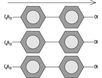
In the manufacture of flat panel displays, two glass substrates are processed separately, then joined together. The front substrate is patterned to create a colour filter array. The rear glass substrate is patterned to form thin film transistors and the metal interconnect lines. These two plates are mated in the assembly process and, if necessary, sliced and separated into individual displays. Liquid crystal material is injected into a gap between the two glass plates. The displays are inspected and tested and a polarizer film is applied to each glass plate.
Numerous individual processes are required to manufacture flat panel displays. They require specialized equipment, materials and processes. Certain key processes are outlined below.
Glass Substrate Preparation
The glass substrate is an essential and expensive component of the display. Very tight control of the optical and mechanical properties of the material is required at every stage of the process, especially when heating is involved.
Glass fabrication
Two processes are used to make very thin glass with very precise dimensions and reproducible mechanical properties. The fusion process, developed by Corning, utilizes a glass feed rod that melts in a wedge-shaped trough and flows up and over the sides of the trough. Flowing down both sides of the trough, the molten glass joins into a single sheet at the bottom of the trough and can be drawn downward as a uniform sheet. The thickness of the sheet is controlled by the speed of drawing down the glass. Widths of up to almost 1 m can be obtained.
Other manufacturers of glass with the appropriate dimensions for LCD substrates use the float method of manufacturing. In this method, the molten glass is allowed to flow out onto a bed of molten tin. The glass does not dissolve or react with the metallic tin, but floats on the surface. This allows gravity to smooth the surface and allow both sides to become parallel. (See the chapter Glass, ceramics and related materials.)
A variety of substrate sizes are available extending to 450 × 550 mm and larger. Typical glass thickness for flat panel displays is 1.1 mm. Thinner glass is used for some smaller displays, such as pagers, telephones, games and so on.
Cutting, bevelling and polishing
Glass substrates are trimmed to size after the fusion or float process, typically to about 1 m on a side. Various mechanical operations follow the forming process, depending on the ultimate application of the material.
Since glass is brittle and easily chipped or cracked at the edges, these are typically bevelled, chamfered or otherwise treated to reduce chipping during handling. Thermal stresses at edge cracks accumulate during substrate processing and lead to breakage. Glass breakage is a significant problem during production. Besides the possibility of employee cuts and lacerations, it represents a yield loss, and glass fragments might remain in equipment, causing particulate contamination or scratching of other substrates.
Increased substrate size results in increased difficulties for glass polishing. Large substrates are mounted to carriers using wax or other adhesive and polished using a slurry of abrasive material. This polishing process must be followed by a thorough chemical cleaning to remove any remaining wax or other organic residue, as well as the metallic contaminants contained in the abrasive or polishing medium.
Cleaning
Cleaning processes are used for bare glass substrates and for substrates covered with organic films, such as colour filters, polyimide orientation films and so on. Also, substrates with semiconductor, insulator and metal films require cleaning at certain points within the fabrication process. As a minimum, cleaning is required prior to each masking step in colour filter or thin film transistor fabrication.
Most flat panel cleaning employs a combination of physical and chemical methods, with selective use of dry methods. After chemical etching or cleaning, substrates are usually dried using isopropyl alcohol. (See table 1.)
Table 1. Cleaning of flat panel displays
|
Physical cleaning |
Dry cleaning |
Chemical cleaning |
|
Brush scrubbing |
Ultraviolet ozone |
Organic solvent* |
|
Jet spray |
Plasma (oxide) |
Neutral detergent |
|
Ultrasonic |
Plasma (non-oxide) |
|
|
Megasonic |
Laser |
Pure water |
* Common organic solvents used in the chemical cleaning include: acetone, methanol, ethanol, n-propanol, xylene isomers, trichloroethylene, tetrachloroethylene.
Colour Filter Formation
Colour filter formation on the front glass substrate includes some of the glass finishing and preparation steps common to both the front and rear panels, including the bevelling and lapping processes. Operations such as patterning, coating and curing are performed repeatedly on the substrate. Many points of similarity with silicon wafer processing exist. Glass substrates are normally handled in track systems for cleaning and coating.
Colour filter patterning
Various materials and application methods are used to create colour filters for various flat panel display types. Either a dyestuff or a pigment can be used, and either one can be deposited and patterned in several ways. In one approach, gelatin is deposited and dyed in successive photolithographic operations, using proximity printing equipment and standard photoresists. In another, pigments dispersed in photoresist are employed. Other methods for forming colour filters include electrodeposition, etching and printing.
ITO Deposition
After colour filter formation, the final step is the sputter deposition of a transparent electrode material. This is indium-tin oxide (ITO), which is actually a mixture of the oxides In2O3 and SnO2. This material is the only one suitable for the transparent conductor application for LCDs. A thin ITO film is required on both sides of the display. Typically, ITO films are made using vacuum evaporation and sputtering.
Thin films of ITO are easy to etch with wet chemicals such as hydrochloric acid, but, as the pitch of the electrodes becomes smaller and features become finer, dry etching may be necessary to prevent undercutting of the lines due to overetching.
Thin Film Transistor Formation
Thin film transistor formation is very similar to the fabrication of an integrated circuit.
Thin film deposition
The substrates begin the fabrication process with a thin film application step. Thin films are deposited by CVD or physical vapour deposition (PVD). Plasma-enhanced CVD, also known as glow discharge, is used for amorphous silicon, silicon nitride and silicon dioxide.
Device patterning
Once the thin film has been deposited, a photoresist is applied and imaged to allow etching of the thin film to the appropriate dimensions. A sequence of thin films is deposited and etched, as with integrated circuit fabrication.
Orientation Film Application and Rubbing
On both the upper and bottom substrate, a thin polymer film is deposited for orientation of the liquid crystal molecules at the glass surface. This orientation film, perhaps 0.1 μm thick, may be a polyimide or other “hard” polymer material. After deposition and baking, it is rubbed with fabric in a specific direction, leaving barely detectable grooves in the surface. Rubbing can be done with a once through cloth on a belt, fed from a roller on one side, passing under a roller which contacts the substrate, onto a roller on the other side. The substrate moves underneath the cloth in the same direction as the cloth. Other methods include a travelling brush that moves across the substrate. The nap of the rubbing material is important. The grooves serve to aid the liquid crystal molecules to align at the substrate surface and to assume the proper tilt angle.
The orientation film can be deposited by spin coating or by printing. The printing method is more efficient in material usage; 70 to 80% of the polyimide is transferred from the printing roll to the substrate surface.
Assembly
Once the substrate rubbing step is completed, an automated assembly line sequence is begun, which consists of:
- adhesive application (required for sealing the panels)
- spacer application
- location and optical alignment of one plate with respect to the other
- exposure (heat or UV) to cure the adhesive and bond the two glass plates together.
Automated transport of both top and bottom plates occurs through the line. One plate receives the adhesive, and the second plate is introduced at the spacer applicator station.
Liquid Crystal Injection
In the case where more than one display has been constructed on the substrate, the displays are now separated by slicing. At this point, the liquid crystal material can be introduced into the gap between the substrates, making use of a hole left in the seal material. This entrance hole is then sealed and prepared for final inspection. Liquid crystal materials are often delivered as two or three component systems which are mixed at injection. Injection systems provide mixing and purging of the cell to avoid trapping bubbles during the filling process.
Inspection and Test
Inspection and functional testing are performed after assembly and liquid crystal injection. Most defects are related to particles (including point and line defects) and cell gap problems.
Polarizer Attachment
The final manufacturing step for the liquid crystal display itself is the application of the polarizer to the outside of each glass plate. Polarizer films are composite films which contain the pressure-sensitive adhesive layer needed to attach the polarizer to the glass. They are applied by automated machines which dispense the material from rolls or pre-cut sheets. The machines are variants of labelling machines developed for other industries. The polarizing film is attached to both sides of the display.
In some cases, a compensation film is applied prior to the polarizer. Compensation films are polymer films (e.g., polycarbonate and polymethyl methacrylate) that are stretched in one direction. This stretching changes the optical properties of the film.
A completed display will ordinarily have driver integrated circuits mounted on or near one of the glass substrates, usually the thin film transistor side.
Hazards
Glass breakage is a significant hazard in LCD manufacturing. Cuts and lacerations can occur. Exposure to chemicals used for cleaning is another concern.
Reporting and Compiling Accident Statistics
The Need for Reporting and Compiling Accident Data
The primary purpose of assembling and analysing occupational accident data is to provide knowledge for use in the prevention of occupational injuries, fatalities and other forms of harm such as toxic exposures with long-term effects. These data are also useful in assessing needs for compensating victims for injuries previously incurred. Additional, more specific purposes for the compilation of accident statistics include the following:
- to estimate the causes and magnitude of accident problems
- to identify and prioritize the need for preventive measures
- to evaluate the effectiveness of preventive measures
- to monitor risks, issue warnings and conduct awareness campaigns
- to provide feedback for those involved in prevention.
Often, an overview of the number of accidents occurring on an annual basis is desired. A frequency is often used for this purpose, comparing the number of accidents to a measure relating to the risk group and expressed, for example, in terms of accidents per 100,000 workers or per 100,000 working hours. Such annual counts serve the purpose of revealing variations in an accident rate from one year to another. However, while they may indicate the sorts of accidents that require the most urgent preventive action, by themselves they do not furnish guidance as to the form that this action should take.
The need for accident information pertains to the following three levels of function that make use of it:
- At the workplace level within the individual enterprise, accident data are used in local safety activities. The best opportunities for tackling specific risk factors are to be found immediately at the workplace itself.
- At the level of authority responsible for legislation, accident data are used to regulate the working environment and to promote safety at the workplace. It is possible not only to exert control over the workplace at this level but also to carry out general statistical analyses for use in overall preventive work.
- At the level of authority responsible for payments of compensation to accident victims, accident data are used to help determine rates.
The Role of the Organization in Compiling Accident Information
In many countries it is a legal requirement that enterprises keep statistics of occupational accidents which result in injury, fatality or toxic exposure to a worker. The purpose of this is usually to call attention to risks that have actually led to these types of accidents, with safety activities focusing chiefly on the particular accident and the study of the event itself. However, it is more common for accident information to be collected and recorded systematically, a function that is ordinarily carried out at a higher level.
Since the actual circumstances of most accidents are special, wholly identical accidents seldom occur, and prevention based on the analysis of the individual accident very readily tends to become a highly specific matter. By systematically compiling accident information it is possible to obtain a broader view of those areas where specific risks are to be found, and to uncover the less obvious factors instrumental in the causation of the accident. Specific work processes, specific work teams or work with specific machinery can give rise to highly circumstantial accidents. However, a close study of the types of accidents associated with a given class of uniform work can disclose such factors as inexpedient work processes, incorrect use of materials, difficult working conditions, or lack of adequate worker instruction. An analysis of numerous recurring accidents will reveal the fundamental factors to be dealt with when preventive action is taken.
Reporting Accident Information to Safety Authorities
Legislation requiring the reporting of occupational accidents varies widely from country to country, with the differences chiefly relating to the classes of employers and others to whom the laws apply. Countries that place significant emphasis on safety at the workplace usually mandate that accident data be reported to the authority responsible for supervising compliance with safety legislation. (In some cases, legislation requires reporting of occupational accidents that result in absence from work, the duration of such absence varying from 1 to 3 days in addition to the day of the accident.) Common to most legislation is the fact that reporting is linked with some sort of penalty or compensation for the consequences of accidents.
For the purpose of supplying a sound foundation for the prevention of occupational accidents, it is necessary to secure accident information pertaining to all sectors and to all types of trades. A basis of comparison should be provided at the national level in order to allow prevention action to be prioritized and in order that knowledge of risks associated with tasks across different sectors may be turned to good account in preventive work. It is therefore recommended that the duty of compiling occupational accident information at the national level apply to all occupational accidents of a designated seriousness, no matter whether they concern employees of firms or the self-employed, persons working at temporary jobs or regular salary earners, or workers in the public or private sectors.
While employers, generally speaking, have a duty to report accidents, it is a duty carried out with varying degrees of enthusiasm. The extent of compliance with the obligation to report accidents depends on the incentives driving the employer to do so. Some countries have a rule, for instance, according to which employers will be compensated for an accident victim’s lost-time pay, an arrangement that gives them good reason to report occupational injuries. Other countries penalize employers who are found to be not reporting accidents. Where these sorts of incentives do not exist, the merely legal obligation binding upon the employer is not always observed. It is moreover recommended that occupational accident information intended for preventive applications be given to the authority responsible for preventive activities, and be kept separate from the compensating authority.
What Information is to be Compiled?
There are three basic classes of information obtainable by means of accident recording:
- Information identifying where the accidents occur - that is, sectors, trades, work processes and so on. This knowledge can be used to determine where preventive action is needed.
- Information showing how the accidents occur, the situations in which they occur and the ways in which the injuries come about. This knowledge can be used to determine the type of preventive action needed.
- Information relating to the nature and seriousness of the injuries, describing, for example, the parts of the body affected and the health consequences of the injuries. Such knowledge is to be used for prioritizing preventive action in order to ensure that action is taken where the risk is highest.
It is necessary to compile a certain basic complement of data to properly document when and where an accident occurs and to analyse how it occurs. At the enterprise level, the data that are collected are more detailed than those assembled at the national level, but reports generated at the local level will contain items of information valuable at all levels. Table 1 illustrates particular sorts of information that might be recorded by way of describing an individual accident. The items especially relevant to the task of preparing statistics relating to the accident are described more fully below.
Table 1. Informational variables characterizing an accident
|
Actions |
Items |
|
Step 1 |
|
|
Activity of the victim: e.g., operating a machine, performing maintenance, driving, walking, etc. |
Component related to the activity of the victim: e.g., power press, tool, vehicle, floor, etc. |
|
Step 2 |
|
|
Deviant action: e.g., explosion, structural failure, trip, lost control of, etc. |
Component related to deviant action: e.g., pressure vessel, wall, cable, vehicle, machine, tool, etc. |
|
Step 3 |
|
|
Action leading to injury: e.g., struck by, crushed, trapped, in contact with, bitten by, etc. |
Agent of injury: e.g., brick, ground, machine, etc. |
Accident identification number. All occupational accidents must be assigned a unique identifying number. It is especially advantageous to use a numerical identifier for the purpose of computerized filing and subsequent processing.
Personal identification number and date. Registration of the victim is an essential part of accident identification. The number can be the worker’s birthday, employment number, social security number or some other unique identifier. Recording both a personal identification number and the date of the accident will prevent duplicated registration of the same accident event, and also enables a check to be made as to whether the accident has been reported. The link between information contained in the accident report with the personal identification number can be protected for the purpose of security.
Nationality. The nationality of the victim may be an especially important item of information in countries with a significantly large foreign labour force. A double-digit code number can be selected from among those listed in the DS/ISO Standard 3166.
Occupation. An occupation registration number can be chosen from the list of four-digit international occupation codes supplied by the International Standard Classification of Occupations (ISCO).
Enterprise. The name, address and identification number of the enterprise are used in the recording of accidents at the national level (although the name and address cannot be used for computer recording). The production sector of the enterprise will usually have been registered with its industrial injury insurance carrier or recorded in connection with the registration of its workforce. A numerical sector identifier can be assigned according to the five-digit NACE international classification system.
The work process. A vital component of information relating to occupational accidents is a description of the work process carried out at the time the accident occurred. Identification of the work process is a prerequisite for accurately targeted prevention. It should be noted that the work process is the actual work function which the victim was performing at the time of the accident and may not necessarily be identical to the work process that caused the injury, fatality or exposure.
The accident event. An accident event normally comprises a chain of events. There is often a tendency on the part of investigators to focus on the part of the event cycle in which the injury actually occurred. From the point of view of prevention, however, a description of that part of the event cycle in which something went wrong, and of what the victim was doing when the event occurred, is just as important.
The consequences of the accident. After the injured part of the body is specified and the type of injury described (this is done partly by coding from a checklist and partly from the description in the event cycle), information is recorded describing the seriousness of the injury, whether it resulted in absence from work (and for how long), or whether it was fatal or involved invalidity. Detailed information in terms of longer-duration absence from work, hospitalization, or disablement is normally available from compensation offices and the social security system.
For recording purposes, the examination of accident events is therefore divided into the following three information components:
- The activity associated with an accident is that which was being carried out by the victim at the time of the accident. It is recorded by means of an action code and a technology code. In this connection, the concept of technology is a broad one, covering such instrumentalities as machines, materials, building components and even animals. At present, there exists no international classification for technology, although Denmark has developed a classification scheme for this purpose.
- The injury event is the deviant event which led to the accident. This is recorded by means of a code for the deviation and by one or two codes for the technology which formed part of the deviation.
- The mode of injury is recorded by using a code for the manner in which the victim came into contact with the injury-causing factor and another code for the technology which caused the injury.
The following examples illustrate the application of these categories of analysis:
- In the event that a worker trips over a hose-pipe while walking and falls, striking his or her head against a table, the activity is walking, the injury event is tripping over the hose-pipe, and the mode of injury is striking the head against the table.
- While a worker is standing near a wall, a tank explodes, causing the wall to collapse on the victim. The activity is merely standing near the wall, the injury event is the explosion of the tank, and the mode of injury is the impact of the wall upon the victim.
Reporting Accident Information
The information to be obtained for each accident can be recorded in a report form similar to that shown in figure 1.

The information from the report form can be recorded on a computer by using classification keys. (Where international classification systems can be recommended, these are mentioned in the description of the individual information variables, given above.) Classifications for the other variables used to record occupational injuries have been developed by the Danish Working Environment Service, and principles to be used in establishing a harmonized recording system form part of a proposal drafted by the European Union.
The Use of Accident Statistics
Accident statistics form a valuable instrument in a wide range of contexts: mapping, monitoring and warning, prioritization of areas for prevention, specific prevention measures, and information retrieval and research. One area may overlap with another, but the principles of application vary.
Mapping
Mapping of occupational accident data involves the extraction of predetermined sorts of information from an accumulation of registered data and the analysis of the interrelationships among them. The following examples will illustrate the utility of the mapping applications.
- Mapping of industrial sectors. Data relating to industrial sectors may be mapped by extracting an appropriate selection of the reports contained in a data register and carrying out the desired analysis. If a trade such as the building industry is of particular interest, reports registered with the International Standard Industrial Classification (ISIC) and coded from 50,000 to 50,199 (building and construction) can be selected. Reports for this trade can then be mapped to show, for example, the geographical location of the enterprises, and the age, sex and occupation of each accident victim.
- Mapping of injuries. If selection is based on a specific category of injuries, the reports can be extracted and mapped to show, for example, the trades in which these accidents occur, the occupational categories involved, the age groups affected, the activities in which the accidents occurred and the kind of technology most often involved.
- Mapping of enterprises. An evaluation on the enterprise level of accident trends (and thus of the internal work environment of the enterprise) can be carried out by mapping the notified occupational accidents that have occurred over a given time period. In addition, the enterprise will be able to compare its individual position with regard to technology, composition of personnel and other areas of concern with the trade as a whole, and thus determine whether its status in these respects is typical of the trade. Furthermore, if a trade proves to contain a number of typical work environment problems, it will be advisable to investigate whether these problems exist within the individual enterprise.
Monitoring and warning
Monitoring is an ongoing surveillance process accompanied by warning of major risks, and particularly of changes in such risks. Changes observed in incoming accident reports either may be indicative of changes in the pattern of reporting, or, more seriously, may reflect genuine changes in risk factors. Major risks may be said to exist where there is a high frequency of injuries, where many serious injuries occur and where there is a large human exposure group.
Establishment of priorities
Establishment of priorities is the selection of the most important risk areas or work-environment problems for preventive action. Through the results of mapping surveys and monitoring and warning activities, a register of occupational accidents can be built which can contribute to this establishment of priorities, the elements of which might include the following:
- risks involving serious consequences
- risks which carry a high probability of injury to a large proportion of the exposure group
- risks to which large groups of people are exposed.
Data drawn from a register of occupational accidents can be used in the establishment of priorities on several levels, perhaps at the overall national level or at the more particular enterprise level. Whatever the level, the analyses and assessments can be made on the basis of the same principles.
Prevention
Analyses and documentation which are used for preventive purposes are generally highly specific and concentrated in limited areas which are, however, treated in great depth. An example of such an analysis is the campaign against fatal accidents conducted by the Danish National Labour Inspection Service. Preliminary mapping surveys identified the trades and work functions in which fatal accidents occurred. Farm tractors were selected as a focal area for analysis. The purpose of the analysis was then to determine what it was that made tractors so dangerous. Questions were investigated as to who drove them, where they were operated, when the accidents occurred and, in particular, what types of situations and events led to the accidents. The analysis produced a description of seven typical situations which most frequently led to accidents. Based on this analysis a preventive programme was formulated.
The number of occupational accidents in a single enterprise is often too small to yield workable statistics for preventive analysis. An analysis of the pattern of accidents may be able to be used to prevent repetition of specific injuries, but can hardly be successful in preventing the occurrence of accidents which in one way or another differ from earlier instances. Unless the focus of investigation is quite a large enterprise, such analyses are therefore best performed on a group of enterprises of very similar nature or on a group of production processes of the same type. For example, an analysis of the lumber industry shows that accidents occurring with cutting machines principally involve finger injuries. Transport accidents predominantly consist of foot and leg injuries, and brain damage and eczema are the most common hazards in the surface-treatment trade. A more detailed analysis of the relevant work processes within the industry can reveal which situations typically cause accidents. Based on this information, experts in the relevant industry can then pinpoint when such situations are likely to arise, and the possibilities for prevention.
Information retrieval and research
One of the most common uses of such information systems as filing and library systems is the retrieval of information of a specific and well-defined nature for the purpose of safety research. For instance, in a study whose aim was to formulate regulations concerning work on roofs, the doubt was raised whether any particular risk was attached to such work. The prevailing belief was that people were very seldom injured by falling from roofs while working. However, in this instance, a register of occupational accidents was used to retrieve all reports in which people had been injured by falling from roofs, and a considerable number of cases were indeed discovered, confirming the importance of continuing to formulate regulations in this area.
Analysis and Reporting: Accident Investigation
It is a paradox that the prevention of work-related accidents did not emerge very early as an absolute necessity, since health and safety is fundamental to work itself. In fact it was not until the beginning of the twentieth century that accidents at work ceased to be considered inevitable and their causation became a subject to be investigated and used as a basis for prevention. However, accident investigation long remained cursory and empirical. Historically, accidents were first conceived of as simple phenomena—that is, as resulting from a single (or principal) cause and a small number of subsidiary causes. It is now recognized that accident investigation, which is aimed at identifying the causes of the phenomenon so as to avert its reoccurrence, depends both on the concept underlying the process of investigation and on the complexity of the situation to which it is applied.
Causes of Accidents
It is indeed true that in the most precarious situations, accidents are often the result of a fairly simple sequence of a few causes that can be rapidly traced to basic technical problems that even a summary analysis can reveal (equipment badly designed, working methods undefined, etc.). On the other hand, the more closely that the material elements of work (machines, installations, the arrangement of the workplace, etc.) conform with the requirements of safe work procedures, standards and regulations, the safer the work situation becomes. The result is that an accident can then occur only when a group of exceptional conditions are present simultaneously—conditions that are becoming ever more numerous. In such cases, the injury or damage appears as the final result of a frequently complex network of causes. This complexity is actually evidence of progress in prevention, and requires appropriate methods of investigation. Table 1 lists the principal concepts of the accident phenomenon, their characteristics and implications for prevention.
Table 1. Principal concepts of the accident phenomenon, their characteristics and the implications for prevention
|
Concept or “accident phenomenon” |
Significant elements (objectives, procedures, limits, etc.) |
Main consequences for prevention |
|
Basic concept (accident as |
The objective is to identify “the” single or main cause |
Simple prevention measures concerning the immediate antecedent of the injury (individual protection, instructions about taking care, protection of dangerous machines) |
|
Concept focused on regulatory measures |
Focus on looking for who is responsible; the “enquiry” essentially identifies infringements and faults Rarely concerned about the conditions generating the situations examined |
Prevention usually limited to reminders about existing regulatory requirements or formal instructions |
|
Linear (or quasi-linear) concept (“domino” model) |
Identification of a chronological succession of “dangerous conditions” and “dangerous acts” |
Conclusions generally concerned with the dangerous acts |
|
Multifactorial concept |
Exhaustive research to gather the facts (circumstances, causes, factors, etc.) |
Concept not conducive to the search for solutions case by case (clinical analysis) and better adapted to the identification of statistical aspects (trends, tables, graphs, etc.) |
|
Systematic concept |
Identification of the network of factors of each accident |
Methods centred on clinical analysis |
Nowadays, a work accident is generally viewed as an index (or symptom) of dysfunction in a system consisting of a single production unit, such as a factory, workshop, team or work position. It is the nature of a system that its analysis requires the investigator to examine not only the elements that make up the system but also their relationships with one another and with the work environment. Within the framework of a system, the accident investigation seeks to trace to its origins the sequence of basic dysfunctions that have resulted in the accident and, more generally, the network of antecedents of the undesired event (accident, near accident or incident).
The application of methods of this kind, such as the STEP method (sequentially timed events plotting procedures) and the “tree of causes” method (similar to fault or event trees analyses), allows the accident process to be visualized in the form of an adjusted graph that illustrates the multicausality of the phenomenon. Because these two methods are so similar, it would represent a duplication of effort to describe them both; accordingly, this article concentrates on the tree of causes method and, where applicable, notes its main differences from the STEP method.
Information Useful for the Investigation
The initial phase of the investigation, the gathering of information, must allow the course of the accident to be described in concrete, precise and objective terms. The investigation therefore sets out to ascertain the tangible facts, taking care not to interpret them or to express an opinion about them. These are the antecedents of the accident, of which there are two types:
- those of an unusual nature (changes or variations) in relation to the “normal” or expected course of the work
- those of a permanent nature that have played an active part in the occurrence of the accident through the medium of or in combination with the unusual antecedents.
For example, insufficient protection of a machine (a permanent antecedent) can turn out to be a factor in an accident if it allows the operator to take up a position in a dangerous area in order to deal with a particular incident (unusual antecedent).
The information gathering is carried out at the location of the accident itself as soon as possible after its occurrence. It is preferably carried out by persons who know the operation or process and who try to obtain a precise description of the work without limiting themselves to the immediate circumstances of the damage or injury. The investigation is initially effected mainly by means of interviews, if possible with the worker or operator, victims and eyewitnesses, other members of the work team, and the hierarchical supervisors. If appropriate it is completed by means of a technical investigation and the use of outside expertise.
The investigation seeks to identify, in order of priority, the unusual antecedents, and to determine their logical connections. An effort is made at the same time to reveal the permanent antecedents that have allowed the accident to occur. In this way the investigation is able to go back to a stage more remote than the immediate antecedents of the accident. These more remote antecedents may concern individuals, their tasks, the equipment that they use, the environment in which they function and the safety culture. By proceeding in the way just described, it is generally possible to draw up a lengthy list of antecedents, but it will usually be difficult to make immediate use of the data. The interpretation of the data is made possible thanks to a graphic representation of all the antecedents involved in the genesis of the accident—that is, a tree of causes.
Constructing a Tree of Causes
The tree of causes presents all the antecedents that have been gathered which have given rise to the accident, as well as the logical and chronological links that connect them; it is a representation of the network of antecedents that have directly or indirectly caused the injury. The tree of causes is constructed starting from the end-point of the event - that is, the injury or damage—and working backwards toward the cause by systematically asking the following questions for each antecedent that has been gathered:
- By which antecedent X was antecedent Y directly caused?
- Was antecedent X sufficient in itself to give rise to antecedent Y?
- If not, have there been other antecedents (X1, X2 Xn) that were equally necessary in order to give rise directly to antecedent Y?
This set of questions can reveal three types of logical connection, summarized in figure 1, among the antecedents.
Figure 1. Logical links used in the "tree of causes" method
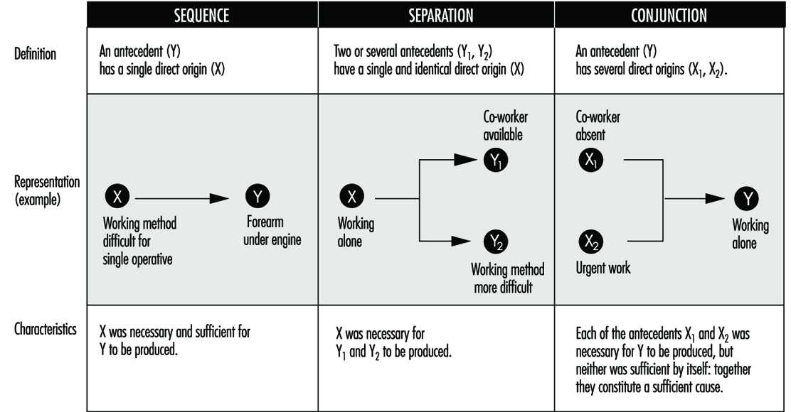
The logical coherence of the tree is checked by asking the following questions for each antecedent:
- If X had not taken place, would Y nevertheless have occurred?
- In order for Y to occur, was X, and only X, necessary?
Moreover, the construction of the tree of causes in itself induces the investigators to pursue the information-gathering, and therefore the investigation, to a point well before the accident occurred. When completed, the tree represents the network of antecedents that have given rise to the injury—they are in fact the accident factors. As an example, the accident summarized below produced the tree of causes shown in figure 2.
Figure 2. Tree of causes of an accident suffered by an apprentice mechanic when remounting an engine in a car
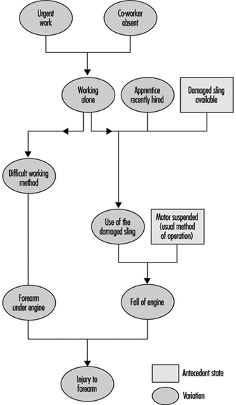
Accident Summary Report: An apprentice mechanic, recently recruited, had to work alone in an emergency. A worn sling was being used to suspend an engine that had to be remounted, and during this operation the sling broke and the engine fell and injured the mechanic’s arm.
Analysis by the STEP Method
According to the STEP method (figure 3), each event is set out graphically so as to show the chronological order of its appearance, keeping one line per “agent” concerned (an agent is the person or thing that determines the course of events constituting the accident process). Each event is described precisely by indicating its beginning, duration, starting and ending place and so on. When there are several plausible hypotheses, the investigator can show them in the network of events by using the logical relationship “or”.
Figure 3. Example of representation possible by the STEP method
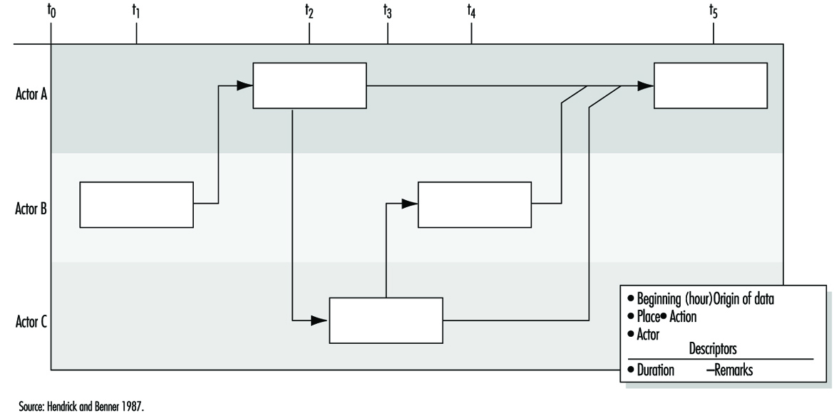
Analysis by the Tree of Causes Method
Making use of the tree of causes for the purposes of accident analysis has two objectives:
- making the reoccurrence of the same accident impossible
- averting the occurrence of more or less similar accidents - that is, accidents whose investigation would reveal common factors with the accidents that have already occurred.
Given the logical structure of the tree, the absence of a single antecedent would have prevented the occurrence of the accident. One judicious prevention measure would therefore suffice, in principle, to satisfy the first objective by preventing the reoccurrence of the same accident. The second objective would require that all the factors discovered should be eliminated, but in practice the antecedents are not all of equal importance for the purposes of prevention. It is therefore necessary to draw up a list of antecedents requiring reasonable and realistic preventive action. If this list is long, a choice has to be made. This choice has more chance of being appropriate if it is made within the framework of a debate between the partners concerned in the accident. Moreover, the debate will gain in clarity to the extent that it is possible to assess the cost-effectiveness of each measure proposed.
Effectiveness of Preventive Measures
The effectiveness of a preventive measure can be judged with the help of the following criteria:
The stability of the measure. The effects of a preventive measure must not disappear with time: informing the operators (in particular, reminding them of instructions) is not a very stable measure because its effects are often transient. The same is moreover true of some protective devices when they are easily removable.
The possibility of integrating safety. When a safety measure is added on - that is, when it does not contribute directly to production - it is said that safety is not integrated. Whenever this is so, it is observed that the measure tends to disappear. Generally speaking, any preventive measure entailing an additional cost for the operator should be avoided, whether it is a physiological cost (increasing the physical or nervous load), a psychological cost, a financial cost (in the case of salary or output) or even a simple loss of time.
The non-displacement of the risk. Some preventive measures may have indirect effects that are detrimental to safety. It is therefore always necessary to foresee the possible repercussions of a preventive measure on the system (job, team or workshop) in which it is inserted.
The possibility of general application (the notion of potential accident factor). This criterion reflects the concern that the same preventive action may be applicable to other jobs than the one affected by the accident under investigation. Whenever possible, an effort should be made to go beyond the particular case that has given rise to the investigation, an effort that often requires a reformulation of the problems discovered. The information obtained from an accident may thus lead to preventive action relating to factors that are unknown but present in other work situations where they have not yet given rise to accidents. For this reason they are called “potential accident factors”. This notion opens the way to the early detection of risks, mentioned later.
The effect on root “causes”. As a general rule, the prevention of accident factors near to the point of injury eliminates certain effects of dangerous situations, while prevention acting well upstream of the injury tends to eliminate the dangerous situations themselves. An in-depth investigation of accidents is justified to the extent that the preventive action is equally concerned with the upstream factors.
The time taken for application. The need to act as rapidly as possible after the occurrence of an accident so as to avoid its reoccurrence is often reflected in the application of a simple preventive measure (an instruction, for example), but this does not eliminate the need for other more lasting and more effective action. Every accident must therefore give rise to a series of proposals whose implementation is the subject of follow-up.
The above criteria are intended to give a better appreciation of the quality of preventive action proposed after each accident investigation. However, the final choice is not made solely on this basis, as other considerations, such as economic, cultural or social ones, must also be taken into account. Finally, the measures decided upon must obviously respect the regulations in force.
Accident Factors
The lessons drawn from each accident analysis deserve to be recorded systematically so as to facilitate passing from knowledge to action. Thus figure 4 consists of three columns. In the left-hand column are noted the accident factors requiring preventive measures. Possible preventive action is described in the middle column for each factor decided upon. After the discussion mentioned above, the action selected is recorded in this part of the document.
Figure 4. Lessons drawn from accidents and the use of these lessons
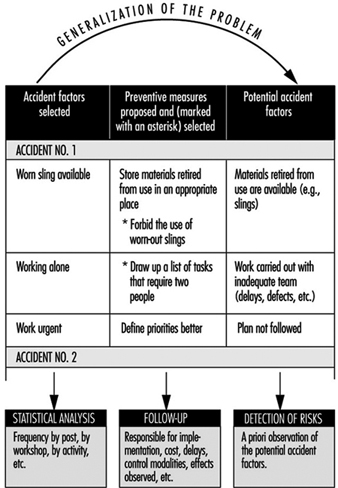
The right-hand column covers the potential accident factors suggested by the factors listed in the left-hand column: it is considered that each accident factor discovered is often only a particular case of a more general factor known as a potential accident factor. The passage from the particular case to the more general case is often made spontaneously. However, each time that an accident factor is expressed in such a fashion that it is not possible to encounter it elsewhere than in the situation in which it has appeared, a more general formulation must be considered. In doing this, it is necessary to avoid two opposite pitfalls so as to utilize the notion of potential accident factor effectively in the early detection of risks arising later. A formulation that is too circumscribed does not permit systematic detection of the factors, whereas one that is too wide makes the notion unworkable and is of no further practical interest. The detection of potential accident factors thus presupposes their being well formulated. This detection can then be carried out in two ways, which are moreover complementary:
- either by looking for the possible presence of potential factors already known at the level of a job or a wider area (workshop, service)
- or by looking for jobs where a factor already determined may be observed.
Usefulness, Effectiveness and Limitations of Accident Investigation
Usefulness. As compared to non-systematic investigations, methods of accident investigation based on a systematic concept have numerous advantages, which include the following:
- They allow the causal network of each accident to be defined collectively, from which it is easier to devise new preventive measures and foresee their impact without being limited to the direct causes of the injury.
- They provide those involved in the analysis with a richer and more realistic mental representation of the “accident phenomenon” that permits a global understanding of work situations.
- In-depth accident investigations (especially when they are extended to cover incidents and undesired events) can become a means and appropriate occasion for dialogue between management and operators.
Effectiveness. In order to be effective, accident investigation requires that four conditions are satisfied concurrently:
- an evident commitment on the part of the top management of the establishment, who must be able to ensure the systematic implementation of such procedures
- training of the investigators
- management, supervisors and workers fully informed concerning the aims of the investigation, its principles, the requirements of the method and the results expected
- real improvements in safety conditions that will encourage those involved in future investigations.
Limitations. Even when carried out very well, accident investigation suffers from a double limitation:
- It remains a procedure for investigating risks a posteriori (in the manner of systems analysis), with the aim of correcting existing situations. It does not therefore dispense with the need for a priori (prospective) investigations, such as the ergonomic investigation of jobs or, for complex systems, safety investigations.
- The usefulness of accident investigations also varies with the safety level of the establishment where they are applied. In particular, when the safety level is high (the accident rate is low or very low), it is evident that serious accidents result from the conjunction of numerous independent random factors that are relatively harmless from the safety viewpoint when considered outside the context under investigation.
Workplace Inspection and Regulatory Enforcement
Inspection Systems
Auditing has been defined as “the structured process of collecting independent information on the efficiency, effectiveness and reliability of the total safety management system and drawing up plans for corrective action” (Successful Health & Safety Management 1991).
The workplace inspection therefore is not only the final stage in setting up a safety management programme but is also a continuing process in its maintenance. It can be conducted only where a properly devised management system for safety has been established. Such a system first envisages a formal policy statement from management setting out its principles for creating a healthy and safe working environment and then establishing the mechanisms and the structures within the organization whereby these principles will be effectively implemented. Management must furthermore be committed to providing adequate resources, both human and financial, to support the system’s mechanisms and structures. Thereafter, there must be detailed planning for safety and health, and the defining of measurable goals. Systems must be devised to ensure that safety and health performance in practice can be measured against established norms and against previous achievements. Only when this structure is in place and is operating can an effective management audit system be applied.
Complete safety and health management systems can be devised, produced and implemented from within the resources of larger enterprises. Additionally, there are a number of safety management control systems which are available from consultants, insurance companies, government agencies, associations and specialist companies. It is a matter for the enterprise to decide whether it should produce its own system or obtain outside services. Both alternatives are capable of producing excellent results if there is a genuine commitment by management to apply them diligently and to make them work. But for their success, they do depend heavily on the quality of the audit system.
Management Inspections
The inspection procedure must be as painstaking and objective as the company’s financial inspection. The inspection must first determine whether the company’s statement of policy on safety and health is properly reflected in the structures and mechanisms created to implement it; if not, then the inspection may recommend that the fundamental policy be reappraised or suggest adjustments or alterations to the existing structures and mechanisms. A similar process must be applied to safety and health planning, to the validity of the goal-setting norms, and to the measurement of performance. The results of any inspection must be considered by the top management of the enterprise, and any correctives must be endorsed and implemented through that authority.
In practice it is undesirable, and often impractical, to undertake a complete inspection of all of a system’s features and their application throughout every department of the enterprise at one time. More usually, the inspection procedure concentrates on one feature of the total safety management system throughout the plant, or alternatively on the application of all the features in one department or even subdepartment. But the objective is to cover all the features in all departments over an agreed period in order to validate the results.
To this extent management inspection should be regarded as a continuous process of vigilance. The need for objectivity is clearly of considerable importance. If inspections are conducted in-house then there must be a standardized inspection procedure; inspections should be undertaken by staff who have been properly trained for this purpose; and those selected as inspectors must not assess the departments in which they normally work, nor should they assess any other work in which they have a personal involvement. Where reliance is placed on consultants this problem is minimized.
Many major companies have adopted this type of system, either devised internally or obtained as a proprietary scheme. When the systems have been carefully followed through from policy statement to inspection, feedback and corrective actions, a substantial reduction in accident rates, which is the prime justification for the procedure, and increased profitability, which is a welcome secondary outcome, should result.
Inspections by Inspectorates
The legal framework which is designed to afford protection to people at work must be properly administered and effectively applied if the purpose of the regulatory legislation is to be achieved. Most countries have therefore adopted the broad model of an inspection service which has the duty of ensuring that safety and health legislation is enforced. Many countries see safety and health issues as part of a complete labour relations package covering industrial relations, wages and holiday agreements, and social benefits. In this model, safety and health inspections are one element of the labour inspector’s duties. A different model also exists in which the state inspectorate is exclusively concerned with safety and health legislation, so that workplace inspections concentrate solely on this aspect. Further variations are evident in the division of the inspection functions between either a national inspectorate or a regional/provincial inspectorate, or indeed, as in Italy and the United Kingdom, for example, as a working combination of both national and regional inspectorates. But whichever model is adopted, the essential function of the inspectorate is to determine compliance with the legislation by a programme of planned inspections and investigations at the workplace.
There can be no effective inspection system unless those who undertake this work are given adequate powers to carry it out. There is much common ground among inspectorates as regards the powers given to them by their legislators. There must always be the right of entry to premises, which is clearly fundamental for inspection. Thereafter there is the legal right to examine relevant documents, registers and reports, to interview members of the workforce either individually or collectively, to have unrestricted access to trade union representatives at the workplace, to take samples of substances or materials at use in the workplace, to take photographs and, if appropriate, to take written statements from people working at the premises.
Additional powers are often provided to enable inspectors to rectify conditions which might be an immediate source of danger or ill health to the workforce. Again there is a wide variety of practices. Where standards are so poor that there is an imminent risk of danger to the workforce, then an inspector may be authorized to serve a legal document on the spot prohibiting the use of the machinery or plant, or stopping the process until the risk has been effectively controlled. For a lower order of risk, inspectors can issue a legal notice formally requiring that measures be taken within a given time to improve standards. These are effective ways of rapidly improving working conditions, and are often a form of enforcement preferable to formal court proceedings, which may be cumbersome and slow in securing remediation.
Legal proceedings have an important place in the hierarchy of enforcement. There is an argument that because court proceedings are simply punitive and do not necessarily result in changing attitudes to safety and health at work, they should therefore be invoked only as a last resort when all other attempts at securing improvements have failed. But this view has to be set against the fact that where legal requirements have been ignored or disregarded, and where people’s safety and health have been significantly put at risk, then the law must be enforced and the courts must decide the issue. There is the further argument that those enterprises which disregard safety and health legislation may thereby enjoy an economic advantage over their competitors, who provide adequate resources to comply with their legal duties. Prosecution of those who persistently disregard their duties is therefore a deterrent to the unscrupulous, and an encouragement to those who try to observe the law.
Every inspection service has to determine the proper balance between providing advice and enforcing the law in the course of inspection work. A special difficulty emerges in connection with the inspection of small enterprises. Local economies, and indeed national economies, are often underpinned by industrial premises each employing fewer than 20 people; in the case of agriculture, the employment figure per unit is very much less. The function of the inspectorate in these cases is to use the workplace inspection to provide information and advice not only on legal requirements, but on practical standards and effective ways of meeting those standards. The technique must be to encourage and stimulate, rather than to immediately enforce the law by punitive action. But even here the balance is a difficult one. People at work are entitled to safety and health standards irrespective of the size of the enterprise, and it would therefore be wholly misguided for an inspection service to ignore or minimize risks and to curtail or even forgo enforcement simply to nurture the existence of the economically fragile small enterprise.
Consistency of Inspections
In the view of the complex nature of their work - with its combined needs for legal, prudential, technical and scientific skills, inspectors do not - indeed should not - adopt a mechanistic approach to inspection. This constraint, combined with a difficult balance between the advisory and enforcement functions, creates yet another concern, that of the consistency of inspection services. Industrialists and trade unions have a right to expect a consistent application of standards, whether technical or legal, by inspectors across the country. In practice this is not always easy to achieve, but it is something for which the enforcing authorities must always strive.
There are ways of achieving an acceptable consistency. First, the inspectorate should be as open as possible in publishing its technical standards and in publicly setting out its enforcement policies. Second, through training, the application of peer review exercises, and internal instructions, it should be able both to recognize a problem and to provide systems to deal with it. Finally, it should ensure that there are procedures for industry, the workforce, the public and the social partners to secure redress if they have a legitimate grievance over inconsistency or other forms of maladministration associated with inspection.
Frequency of Inspections
How frequently should the inspectorates undertake inspections of the workplace? Again there is considerable variation in the way this question may be answered. The International Labour Organization (ILO) holds the view that the minimum requirement should be that every workplace should receive an inspection from the enforcing authorities at least once each year. In practice, few countries manage to produce a programme of work inspection which meets this objective. Indeed, since the major economic depression in the late 1980s some governments have been curtailing inspection services by budget limitations that result in cutbacks in the number of inspectors, or by restrictions on recruiting new staff to replace those who retire.
There are different approaches to determine how frequently inspections should be made. One approach has been purely cyclical. Resources are deployed to provide inspection of all premises on a 2-yearly, or more likely a 4-yearly, basis. But this approach, though possibly having the appearance of equity, treats all premises as the same regardless of size or risk. Yet enterprises are manifestly diverse as regards safety and health conditions, and to the extent that they differ, this system may be regarded as mechanistic and flawed.
A different approach, adopted by some inspectorates, has been to attempt to draw up a programme of work based on hazard; the greater the hazard either to safety or health, the more frequent the inspection. Hence resources are applied by the inspectorate to those places where the potential for harm to the workforce is the greatest. Although this approach has merits, there are still considerable problems associated with it. First, there are difficulties in accurately and objectively assessing hazard and risk. Second, it extends very considerably the intervals between inspections of those premises where hazards and risks are considered to be low. Therefore, extended periods may elapse during which many of the workforce may have to forgo that sense of security and assurance which inspection can provide. Furthermore, the system tends to presume that hazards and risks, once assessed, do not radically change. This is far from being the case, and there is the danger that a low-rated enterprise may change or develop its production in such a way as to increase hazards and risk without the inspectorate’s being aware of the development.
Other approaches include inspections based on facility injury rates which are higher than the national averages for the particular industry, or immediately following a fatal injury or major catastrophe. There are no short and easy answers to the problem of determining the frequency of inspection, but what seems to be happening is that inspection services in many countries are too often significantly under-resourced, with the result that the real protection to the workforce afforded by the service is being progressively eroded.
Inspection Goals
Inspection techniques in the workplace vary according to the size and complexity of the enterprise. In smaller companies, the inspection will be comprehensive and will assess all hazards and the extent to which the risks arising from the hazards have been minimized. The inspection will therefore ensure that the employer is fully aware of safety and health problems and is given practical guidance on how they may be addressed. But even in the smallest enterprise the inspectorate should not give the impression that fault-finding and the application of suitable remedies are the function of the inspectorate and not of the employer. Employers must be encouraged by inspection to control and effectively manage safety and health problems, and they must not abdicate their responsibilities by awaiting an inspection from the enforcement authorities before taking needed action.
In larger companies, the emphasis of inspection is rather different. These companies have the technical and financial resources to deal with safety and health problems. They should devise both effective management systems to resolve the problems, as well as management procedures to check that the systems are working. In these circumstances, the inspection emphasis should therefore be on checking and validating the management control systems found at the workplace. The inspection should therefore not be an exhaustive examination of all items of plant and equipment to determine their safety, but rather to use selected examples to test the effectiveness or otherwise of the management systems for ensuring safety and health at work.
Worker Involvement in Inspections
Whatever the premises, a critical element in any type of inspection is contact with the workforce. In many smaller premises, there may be no formal trade union structure or indeed any workforce organization at all. However, to ensure the objectivity and acceptance of the inspection service, contact with individual workers should be an integral part of the inspection. In larger enterprises, contact should always be made with trade union or other recognized worker representatives. Legislation in some countries (Sweden and the United Kingdom, for example) gives official recognition and powers to trade union safety representatives, including the right to make workplace inspections, to investigate accidents and dangerous occurrences and in some countries (though this is exceptional) to stop plant machinery or the production process if it is imminently dangerous. Much useful information can be gained from these contacts with the workers, which should feature in every inspection, and certainly whenever the inspectorate is conducting an inspection as the result of an accident or a complaint.
Inspection Findings
The final element in an inspection is to review the inspection findings with the most senior member of management on the site. Management has the prime responsibility to comply with legal requirements on safety and health, and therefore no inspection should be complete without management’s being fully aware of the extent to which it has met those duties, and what needs to be done to secure and maintain proper standards. Certainly if any legal notices are issued as a result of an inspection, or if legal proceedings are likely, then senior management must be aware of this state of affairs at the earliest possible stage.
Company Inspections
Company inspections are an important ingredient in maintaining sound standards of safety and health at work. They are appropriate to all enterprises and, in larger companies, may be an element in the management inspection procedure. For smaller companies, it is essential to adopt some form of regular company inspection. Reliance should not be placed on the inspection services provided by the inspectorates of the enforcing authorities. These are usually far too infrequent, and should serve largely as a stimulus to improve or maintain standards, rather than be the primary source for evaluating standards. Company inspections can be undertaken by consultants or by companies who specialize in this work, but the current discussion will concentrate on inspection by the enterprise’s own personnel.
How frequently should company inspections be made? To some degree the answer is dependent on the hazards associated with the work and the complexity of the plant. But even in low-risk premises there should be some form of inspection on a regular (monthly, quarterly, etc.) basis. If the company employs a safety professional, then clearly the organization and the conduct of the inspection must be an important part of this function. The inspection should usually be a team effort involving the safety professional, the departmental manager or foreman, and either a trade union representative or a qualified worker, such as a safety committee member. The inspection should be comprehensive; that is to say, a close examination should be made both of the safety software (for example, systems, procedures and work permits) and the hardware (for example, machinery guarding, fire-fighting equipment, exhaust ventilation and personal protective equipment). Particular attention should be paid to “near misses” - those incidents which do not result in damages or personal injury but which have the imminent potential for serious accidental injuries. There is an expectation that after an accident resulting in absence from work, the inspection team would immediately convene to investigate the circumstances, as a matter outside the normal cycle of inspection. But even during routine workshop inspection the team should also consider the extent of minor accidental injuries which have occurred in the department since the previous inspection.
It is important that company inspections should not seem to be consistently negative. Where faults exist it is important that they be identified and rectified, but it is equally important to commend the maintenance of good standards, to comment positively on tidiness and good housekeeping, and to reinforce by encouragement those who use personal protective equipment provided for their safety. To complete the inspection a formal written report should be made of the significant deficiencies found. Particular attention should be drawn to any shortcomings which have been identified in previous inspections but have not yet been corrected. Where there exists a works safety council, or a joint management-worker safety committee, the inspection report should be featured as a standing item on the council’s agenda. The report on the inspection must be sent to and discussed with the senior management of the enterprise, who should then determine whether action is required and, if so, authorize and support such action.
Even the smallest companies, where there is no safety professional, and where trade unions may not exist, should consider company inspections. Many inspectorates have produced very simple guidelines illustrating the basic concepts of safety and health, their application to a range of industries, and practical ways in which they can be applied in even the smallest enterprises. Many safety associations specifically target small businesses with publications (often free) which provide the basic information to establish safe and healthy working conditions. Armed with this sort of information and with the expenditure of very little time, the proprietor of a small business can establish reasonable standards, and can thus perhaps obviate the sort of accidents which can happen to the workforce in even the smallest business.
Hazard Analysis: Organizational Factors - mort
Through industrialization, workers became organized in factories as the utilization of energy sources such as the steam engine became possible. As compared to traditional handicraft, mechanized production, with sources of higher energy at its disposal, presented new risks of accidents. As the amount of energy increased, workers were removed from the direct control of these energies. Decisions that affected safety were often made at the management level rather than by those directly exposed to these risks. At this stage of industrialization, the need for safety management became evident.
In the late 1920s, Heinrich formulated the first comprehensive theoretical framework for safety management, which was that safety should be sought through management decisions based on identification and analysis of accident causes. At this point in the development of safety management, accidents were attributed to failures at the worker-machine system level - that is, to unsafe acts and unsafe conditions.
Subsequently, various methodologies were developed for the identification and assessment of accident risks. With MORT (Management Oversight and Risk Tree), the focus shifted to the higher orders of control of accident risks - that is, to the control of conditions at the management level. The initiative to develop MORT was taken in the late 1960s by the US Energy Research and Development Administration, which wanted to improve their safety programmes in order to reduce their losses due to accidents.
The MORT Diagram and Underlying Principles
The intent of MORT was to formulate an ideal safety management system based on a synthesis of the best safety programme elements and safety management techniques then available. As the principles underlying the MORT initiative were applied to the contemporary state of the art in safety management, the largely unstructured safety literature and expertise took on the form of an analytical tree. The first version of the tree was published in 1971. Figure 1 shows the basic elements of the version of the tree that was published by Johnson in 1980. The tree also appears in a modified form in later publications on the subject of the MORT concept (see, for example, Knox and Eicher 1992).
Figure 1. A version of the MORT analytical tree

The MORT Diagram
MORT is used as a practical tool in accident investigations and in evaluations of existing safety programmes. The top event of the tree in figure 1 (Johnson 1980) represents the losses (experienced or potential) due to an accident. Below this top event are three main branches: specific oversights and omissions (S), management oversights and omissions (M) and assumed risks (R). The R-branch consists of assumed risks, which are events and conditions that are known to management and that have been evaluated and accepted at the proper management level. Other events and conditions that are revealed through the evaluations following the S- and M-branches are denoted “less than adequate” (LTA).
The S-branch focuses on the events and conditions of the actual or potential occurrence. (In general, time is shown as one reads from left to right, and the sequence of causes is shown as one reads from bottom to top.) Haddon’s strategies (1980) for the prevention of accidents are key elements in this branch. An event is denoted an accident when a target (a person or object) is exposed to an uncontrolled transfer of energy and sustains damage. In the S-branch of MORT, accidents are prevented through barriers. There are three basic types of barriers: (1) barriers that surround and confine the energy source (the hazard), (2) barriers that protect the target and (3) barriers that separate the hazard and the target physically or in time or space. These different types of barriers are found in the development of the branches below the accidental event. Amelioration relates to the actions taken after the accident to limit the losses.
At the next level of the S-branch, factors are recognized which relate to the different phases of the life cycle of an industrial system. These are the project phase (design and plan), start up (operational readiness) and operation (supervision and maintenance).
The M-branch supports a process in which specific findings from an accident investigation or safety programme evaluation are made more general. Events and conditions of the S-branch thus often have their counterparts in the M-branch. When engaged with the system at the M-branch, the analyst’s thinking is expanded to the total management system. Thus, any recommendations will affect many other possible accident scenarios as well. The most important safety management functions can be found in the M-branch: the setting of policy, implementation and follow-up. These are the same basic elements that we find in the quality assurance principles of the ISO 9000 series published by the International Organization for Standardization (ISO).
When the branches of the MORT diagram are elaborated in detail, there are elements from such different fields as risk analysis, human factors analysis, safety information systems and organizational analysis. In total, about 1,500 basic events are covered by the MORT diagram.
Application of the MORT Diagram
As indicated, the MORT diagram has two immediate uses (Knox and Eicher 1992): (1) to analyse management and organizational factors relative to an accident that has happened and (2) to evaluate or audit a safety programme in relation to a significant accident that has the potential of occurring. The MORT diagram functions as a screening tool in planning the analyses and evaluations. It is also used as a checklist for comparison of actual conditions with the idealized system. In this application, MORT facilitates checking the completeness of the analysis and avoiding personal biases.
At bottom, MORT is made up of a collection of questions. Criteria that guide judgements as to whether specific events and conditions are satisfactory or less than adequate are derived from these questions. In spite of the directive design of the questions, the judgements made by the analyst are partly subjective. It has thus become important to ensure an adequate quality and degree of intersubjectivity among MORT analyses made by different analysts. For example, in the United States, a training programme is available for certification of MORT analysts.
Experiences with MORT
The literature on evaluations of MORT is sparse. Johnson reports significant improvements in the comprehensiveness of accident investigations after the introduction of MORT (Johnson 1980). Deficiencies at the supervisory and management levels were revealed more systematically. Experience has also been gained from evaluations of MORT applications within Finnish industry (Ruuhilehto 1993). Some limitations have been identified in the Finnish studies. MORT does not support the identification of immediate risks due to failures and disturbances. Furthermore, no capability for setting priorities is built into the MORT concept. Consequently, the results of MORT analyses need further evaluation to translate them into remedial actions. Finally, experience shows that MORT is time-consuming and requires expert participation.
Aside from its ability to focus on organizational and management factors, MORT has the further advantage of connecting safety with normal production activities and general management. The application of MORT will thus support general planning and control, and help reduce the frequency of production disturbances as well.
Associated Safety Management Methods and Techniques
With the introduction of the MORT concept in the early 1970s, a development programme started in the United States. The focal point for this programme has been the System Safety Development Center in Idaho Falls. Different MORT-associated methods and techniques in such areas as human factors analysis, safety information systems and safety analysis have resulted from this programme. An early example of a method arising from the MORT development programme is the Operational Readiness Program (Nertney 1975). This programme is introduced during the development of new industrial systems and modifications of existing ones. The aim is to ensure that, from the safety management point of view, the new or modified system is ready at the time of start-up. A condition of operational readiness presupposes that the necessary barriers and controls have been installed in the new system’s hardware, personnel and procedures. Another example of a MORT programme element is the MORT-based root cause analysis (Cornelison 1989). It is used to identify the basic safety management problems of an organization. This is done by relating the specific findings of the MORT analyses to 27 different generic safety management problems.
Although MORT is not intended for use directly in the collection of information during accident investigations and safety audits, in Scandinavia, the MORT questions have served as a basis for the development of a diagnostic tool used for this purpose. It is called the Safety Management and Organization Review Technique, or SMORT (Kjellén and Tinmannsvik 1989). A SMORT analysis advances backwards in steps, starting from the specific situation and ending at the general management level. The starting point (level 1) is an accident sequence or a risk situation. At level 2, the organization, system planning and technical factors related to daily operation are scrutinized. The subsequent levels include design of new systems (level 3) and higher management functions (level 4). Findings on one level are extended to the levels above. For example, results related to the accident sequence and to daily operations are used in the analysis of the company’s organization and routines for project work (level 3). Results at level 3 will not affect safety in existing operations but may be applied to the planning of new systems and modifications. SMORT also differs from MORT in the way findings are identified. At level 1, these are observable events and conditions that deviate from generally accepted norms. When organizational and management factors are brought into the analysis at levels 2 to 4, the findings are identified through value judgements made by an analysis group and verified through a quality control procedure. The aim is to ensure a mutually shared understanding of the organizational problems.
Summary
MORT has been instrumental in developments within safety management since the 1970s. It is possible to track the influence of MORT to such areas as safety research literature, literature on safety management and audit tools, and legislation on self-regulation and internal control. In spite of this impact, its limitations must be carefully considered. MORT and associated methods are normative in the sense that they prescribe how safety management programmes should be organized and executed. The ideal is a well-structured organization with clear and realistic goals and well-defined lines of responsibility and authority. MORT is thus best suited for large and bureaucratic organizations.
" DISCLAIMER: The ILO does not take responsibility for content presented on this web portal that is presented in any language other than English, which is the language used for the initial production and peer-review of original content. Certain statistics have not been updated since the production of the 4th edition of the Encyclopaedia (1998)."