- You are here:
-
Home

- k2 Feed
Stigmata
Occupational stigma or occupational marks are work-induced anatomical lesions which do not impair working capacity. Stigmata are generally caused by mechanical, chemical or thermal skin irritation over a long period and are often characteristic of a particular occupation. Any kind of pressure or friction on the skin may produce an irritating effect, and a single violent pressure may break the epidermis, leading to the formation of excoriations, seropurulent blisters and infection of the skin and underlying tissues. On the other hand, however, frequent repetition of moderate irritant action does not disrupt the skin but stimulates defensive reactions (thickening and keratinization of the epidermis). The process may take three forms:
- a diffuse thickening of the epidermis which merges into the normal skin, with preservation and occasional accentuation of skin ridges and unimpaired sensitivity
- a circumscribed callosity made up of smooth, elevated, yellowish, horny lamellae, with partial or complete loss of skin ridges and impairment of sensitivity. The lamellae are not circumscribed; they are thicker in the centre and thinner towards the periphery and blend into the normal skin
- a circumscribed callosity, mostly raised above the normal skin, 15 mm in diameter, yellowish-brown to black in colour, painless and occasionally associated with hypersecretion of the sweat glands.
Callosities are usually produced by mechanical agents, sometimes with the aid of a thermal irritant (as in the case of glass- blowers, bakers, firefighters, meat curers, etc.), when they are dark-brown to black in colour with painful fissures. If, however, the mechanical or thermal agent is combined with a chemical irritant, callosities undergo discoloration, softening and ulceration.
Callosities which represent a characteristic occupational reaction (particularly on the skin of the hand as shown in figure 1 and 2) are seen in many occupations. Their form and localization are determined by the site, force, manner and frequency of the pressure exerted, as well as by the tools or materials used. The size of callosities may also reveal a congenital tendency to skin keratinization (ichthyosis, hereditary keratosis palmaris). These factors may also often be decisive as concerns deviations in the localization and size of callosities in manual workers.
Figure 1. Occupational stigmata on the hands.

(a) Tanner’s ulcers; (b) Blacksmith; (c) Sawmill worker; (d) Stonemason; (e) Mason; (f) Marble Mason; (g) Chemical factory worker; (h) Paraffin refinery worker; (I) Printer; (j) Violinist
(Photos: Janina Mierzecka.)
Figure 2. Calluses at pressure points on the palm of the hand.

Callosities normally act as protective mechanisms but may, under certain conditions, acquire pathological features; for this reason they should not be overlooked when pathogenesis and, particularly, prophylaxis of occupational dermatoses are envisaged.
When a worker gives up a callosity-inducing job, the superfluous horny layers undergo exfoliation, the skin becomes thin and soft, the discoloration disappears and the normal appearance is restored. The time required for skin regeneration varies: occupational callosities on the hands may occasionally be seen several months or years after the work has been given up (especially in blacksmiths, glass-blowers and sawmill workers). They persist longer in senile skin and when associated with connective tissue degeneration and bursitis.
Fissures and erosions of the skin are characteristic of certain occupations (railway workers, gunsmiths, bricklayers, goldsmiths, basket weavers, etc.). The painful “tanner’s ulcer” associated with chromium compound exposures (figure 1) round or oval in shape and from 2-10 mm in diameter. The localisation of occupational lesions (e.g. on confectioners’ fingers, tailors’ fingers and palms, etc.) is also characteristic.
Pigment spots are caused by the absorption of dyes through the skin, the penetration of particles of solid chemical compounds or industrial metals, or the excessive accumulation of the skin pigment, melanin, in workers in coking or generator plants, after three to five years of work. In some establishments, about 32% of workers were found to exhibit melanomata. Pigment spots are mostly found in chemical workers.
As a rule, dyes absorbed through the skin cannot be removed by routine washing, hence their permanence and significance as occupational stigmata. Pigment spots occasionally result from impregnation with chemical compounds, plants, soil or other substances to which the skin is exposed during the work process.
A number of occupational stigmata may be seen in the region of the mouth (e.g. Burton’s line within the gums of workers exposed to lead, teeth erosion in workers exposed to acid fumes, etc. blue colouring of the lips in workers engaged in aniline manufacture and in the form of acne. Characteristic odours connected with certain occupations may also be considered as occupational stigmata.
Checklists
Work systems encompass such macro level organizational variables as the personnel subsystem, the technological subsystem and the external environment. The analysis of work systems is, therefore, essentially an effort to understand the allocation of functions between the worker and the technical outfit and the division of labour between people in a sociotechnical environment. Such an analysis can assist in making informed decisions to enhance systems safety, efficiency in work, technological development and the mental and physical well-being of workers.
Researchers examine work systems according to divergent approaches (mechanistic, biological, perceptual/motor, motivational) with corresponding individual and organizational outcomes (Campion and Thayer 1985). The selection of methods in work systems analysis is dictated by the specific approaches taken and the particular objective in view, the organizational context, the job and human characteristics, and the technological complexity of the system under study (Drury 1987). Checklists and questionnaires are the common means of assembling databases for organizational planners in prioritizing action plans in areas of personnel selection and placement, performance appraisal, safety and health management, worker-machine design and work design or redesign. Inventory methods of checklists, for example the Position Analysis Questionnaire, or PAQ (McCormick 1979), the Job Components Inventory (Banks and Miller 1984), the Job Diagnostic Survey (Hackman and Oldham 1975), and the Multi-method Job Design Questionnaire (Campion 1988) are the more popular instruments, and are directed to a variety of objectives.
The PAQ has six major divisions, comprising 189 behavioural items required for the assessment of job performance and seven supplementary items related to monetary compensation:
- information input (where and how does one get information on the jobs to perform) (35 items)
- mental process (information processing and decision-making in performing the job) (14 items)
- work output (physical work done, tools and devices used) (50 items)
- interpersonal relationships (36 items)
- work situation and job context (physical/social contexts) (18 items)
- other job characteristics (work schedules, job demands) (36 items).
The Job Components Inventory Mark II contains seven sections. The introductory section deals with the details of the organization, job descriptions and biographical details of the job holder. Other sections are as follows:
- tools and equipment—uses of over 200 tools and equipment (26 items)
- physical and perceptual requirements—strength, coordination, selective attention (23 items)
- mathematical requirements—uses of numbers, trigonometry, practical applications, e.g., work with plans and drawings (127 items)
- communication requirements—the preparation of letters, use of coding systems, interviewing people (19 items)
- decision-making and responsibility—decisions about methods, order of work, standards and related issues (10 items)
- job conditions and perceived job characteristics.
The profile methods have common elements, that is, (1) a comprehensive set of job factors used to select the range of work, (2) a rating scale that permits the evaluation of job demands, and (3) the weighing of job characteristics based on organizational structure and sociotechnical requirements. Les profils des postes, another task profile instrument, developed in the Renault Organization (RNUR 1976), contains a table of entries of variables representing working conditions, and provides respondents with a five-point scale on which they can select the value of a variable that ranges from very satisfactory to very poor by way of registering standardized responses. The variables cover (1) the design of the workstation, (2) the physical environment, (3) the physical load factors, (4) nervous tension, (5) job autonomy, (6) relations, (7) repetitiveness and (8) contents of work.
The AET (Ergonomic Job Analysis) (Rohmert and Landau 1985), was developed based on the stress-strain concept. Each of the 216 items of the AET are coded: one code defines the stressors, indicating whether a work element does or does not qualify as a stressor; other codes define the degree of stress associated with a job; and yet others describe the duration and frequency of stress during the work shift.
The AET consists of three parts:
- Part A. The Man-at-Work system (143 items) includes the work objects, tools and equipment, and work environment constituting the physical, organizational, social and economic conditions of work.
- Part B. The Task analysis (31 items) classified according to both the different kinds of work object, such as material and abstract objects, and worker-related tasks.
- Part C. The Work Demand analysis (42 items) comprises the elements of perception, decision and response/activity. (The AET supplement, H-AET, covers body postures and movements in industrial assembling activities).
Broadly speaking, the checklists adopt one of two approaches, (1) the job-oriented approach (e.g., the AET, Les profils des postes) and (2) the worker-oriented approach (e.g., the PAQ). The task inventories and profiles offer subtle comparison of complex tasks and occupational profiling of jobs and determine the aspects of work which are considered a priori as inevitable factors in improving working conditions. The emphasis of the PAQ is on classifying job families or clusters (Fleishman and Quaintence 1984; Mossholder and Arvey 1984; Carter and Biersner 1987), inferring job component validity and job stress (Jeanneret 1980; Shaw and Riskind 1983). From the medical point of view, both the AET and the profile methods allow comparisons of constraints and aptitudes when required (Wagner 1985). The Nordic questionnaire is an illustrative presentation of ergonomic workplace analysis (Ahonen, Launis and Kuorinka 1989), which covers the following aspects:
- work space
- general physical activity
- lifting activity
- work postures and movements
- accident risk
- job content
- job restrictiveness
- worker’s communication and personal contacts
- decision-making
- repetitiveness of the work
- attentiveness
- lighting conditions
- thermal environment
- noise.
Among the shortcomings of the general-purpose checklist format employed in ergonomic job analysis are the following:
- With some exceptions (e.g., the AET, and the Nordic questionnaire), there is a general lack of ergonomics norms and protocols of evaluation with respect to the different aspects of work and environment.
- There are dissimilarities in the overall construction of the checklists as regards means of determining the characteristics of working conditions, the quotation form, criteria and methods of testing.
- The evaluation of physical workload, work postures and work methods is limited on account of lack of precision in the analysis of work operations, with reference to the scale of relative levels of stress.
- The principal criteria of assessment of the worker’s mental load are the degree of complexity of the task, the attention required by the task and the execution of mental skills. The existing checklists refer less to underuse of abstract thought mechanisms than to overuse of concrete thought mechanisms.
- In most checklists, methods of analysis attach major importance to the job as a position as opposed to the analysis of work, worker-machine compatibility, and so forth. The psycho-sociological determinants, which are fundamentally subjective and contingent, are less emphasized in the ergonomics checklists.
A systematically constructed checklist obliges us to investigate the factors of work conditions which are visible or easy to modify, and permits us to engage in a social dialogue between employers, job holders and others concerned. One should exercise a degree of caution towards the illusion of simplicity and efficiency of the checklists, and towards their quantifying and technical approaches as well. Versatility in a checklist or questionnaire can be achieved by including specific modules to suit specific objectives. Therefore, the choice of variables is very much linked to the purpose for which the work systems are to be analysed and this determines the general approach for construction of a user-friendly checklist.
The suggested “Ergonomics Checklist” may be adopted for various applications. Data collection and computerized processing of the checklist data are relatively straightforward, by responding to the primary and secondary statements (q.v.).
ERGONOMICS CHECKLIST
A broad guideline for a modular-structured work systems checklist is suggested here, covering five major aspects (mechanistic, biological, perceptual/motor, technical and psychosocial). Weighting of the modules varies with the nature of the job(s) to be analysed, the specific features of the country or population under study, organizational priorities and the intended use of the results of the analysis. Respondents mark the “primary statement” as Yes/No. “Yes” answers indicate the apparent absence of a problem, although the advisability of further careful scrutiny should not be ruled out. “No” answers indicate a need for an ergonomics evaluation and improvement. Responses to “secondary statements” are indicated by a single digit on the severity of agreement/disagreement scale illustrated below.
0 Do not know or not applicable
1 Strongly disagree
2 Disagree
3 Neither agree nor disagree
4 Agree
5 Strongly agree
A. Organization, worker and the task Your answers/ratings
The checklist designer may provide a sample drawing/photograph of work and
workplace under study.
1. Description of organization and functions.
_______________________________________________________________
_______________________________________________________________
_______________________________________________________________
_______________________________________________________________
2. Worker characteristics: A brief account of the work group.
_______________________________________________________________
_______________________________________________________________
_______________________________________________________________
_______________________________________________________________
3. Task description: List activities and materials in use. Give some indication of
the work hazards.
_______________________________________________________________
_______________________________________________________________
_______________________________________________________________
_______________________________________________________________
B. Mechanistic aspect Your answers/ratings
I. Job Specialization
4.Tasks/work patterns are simple and uncomplicated. Yes/No
If No, rate the following: (Enter 0-5)
4.1 Job assignment is specific to the operative. ![]()
4.2 Tools and methods of work are specialized to the purpose of the job. ![]()
4.3 Production volume and quality of work. ![]()
4.4 Job holder performs multiple tasks. ![]()
II. Skill Requirement
5. Job requires simple motor act. Yes/No
If No, rate the following: (Enter 0-5)
5.1 Job requires knowledge and skilful ability. ![]()
5.2 Job demands training for skill acquisition. ![]()
5.3 Worker makes frequent mistakes at work. ![]()
5.4 Job demands frequent rotation, as directed. ![]()
5.5 Work operation is machine paced/assisted by automation. ![]()
Remarks and suggestions for improvement. Items 4 to 5.5:
_______________________________________________________________
_______________________________________________________________
_______________________________________________________________
_______________________________________________________________
q Analyst’s rating Worker’s rating q
C. Biological aspect Your answers/ratings
III. General Physical Activity
6. Physical activity is entirely determined and
regulated by the worker. Yes/No
If No, rate the following: (Enter 0-5)
6.1 Worker maintains target-oriented pace. ![]()
6.2 Job implies frequently repeated movements. ![]()
6.3 Cardiorespiratory demand of the job: ![]()
sedentary/light/moderate/heavy/ extremely heavy.
(What are the heavy work elements?):
_______________________________________________________________
_______________________________________________________________
_______________________________________________________________
_______________________________________________________________
(Enter 0-5)
6.4 Job demands high muscular strength exertion. ![]()
6.5 Job (operation of handle, steering wheel, pedal brake) is predominantly static work. ![]()
6.6. Job requires fixed working position (sitting or standing). ![]()
IV. Manual Materials Handling (MMH)
Nature of objects handled: animate/inanimate, size and shape.
_______________________________________________________________
_______________________________________________________________
7. Job requires minimal MMH activity. Yes/No
If No, specify the work:
7.1 Mode of work: (circle one)
pull/push/turn/lift/lower/carry
(Specify repetition cycle):
_______________________________________________________________
_______________________________________________________________
7.2 Load weight (kg): (circle one)
5-10, 10-20, 20-30, 30-40, >>40.
7.3 Subject-load horizontal distance (cm): (circle one)
<25, 25-40, 40-55, 55-70, >70.
7.4 Subject-load height: (circle one)
ground, knee, waist, chest, shoulder level.
(Enter 0-5)
7.5 Clothing restricts MMH tasks. ![]()
8. Task situation is free from risk of bodily injury. Yes/No
If No, rate the following: (Enter 0-5)
8.1 Task can be modified to reduce the load to be handled. ![]()
8.2 Materials can be packed in standard sizes. ![]()
8.3 Size/position of handles on objects may be improved. ![]()
8.4 Workers do not adopt safer methods of load handling. ![]()
8.5 Mechanical aids may reduce bodily strains.
List each item if hoists or other handling aids are available. ![]()
Suggestions for improvement, Items 6 to 8.5:
_______________________________________________________________
_______________________________________________________________
_______________________________________________________________
_______________________________________________________________
V. Workplace/Workspace Design
Workplace may be diagrammatically illustrated, showing human reach and
clearance:
9. Workplace is compatible with human dimensions. Yes/No
If No, rate the following: (Enter 0-5)
9.1 Work distance is away from normal reach in the horizontal or vertical plane (>60 cm). ![]()
9.2 Height of work desk/equipment is fixed or minimally adjustable. ![]()
9.3 No space for subsidiary operations (e.g., inspection and maintenance). ![]()
9.4 Workstations have obstacles, protruding parts or sharp edges. ![]()
9.5 Work surface floors are slippery, uneven, cluttered or unstable. ![]()
10. Seating arrangement is adequate (e.g., comfortable chair,
good postural support). Yes/No
If No, the causes are: (Enter 0-5)
10.1 Seat dimensions (e.g., seat height, back rest) mismatch with human dimensions. ![]()
10.2 Minimum adjustability of seat. ![]()
10.3 Workseat provides no hold/support (e.g., by means of vertical edges/extra stiff covering) to work with the machinery. ![]()
10.4 Absence of vibration damping mechanism in the workseat. ![]()
11. Sufficient auxiliary support is available for safety
at the workplace. Yes/No
If No, mention the following: (Enter 0-5)
11.1 Non-availability of storage space for tools, personal articles. ![]()
11.2 Doorways, entrance/exit routes, or corridors are restricted. ![]()
11.3 Design mismatch of handles, ladders, staircases, handrails. ![]()
11.4 Handholds and footholds demand awkward position of limbs. ![]()
11.5 Supports are unrecognizable by their place, form or construction. ![]()
11.6 Limited use of gloves/footwear to work and operate equipment controls. ![]()
Suggestions for improvement, Items 9 to 11.6:
_______________________________________________________________
_______________________________________________________________
_______________________________________________________________
_______________________________________________________________
VI. Work Posture
12. Job allows a relaxed work posture. Yes/No
If No, rate the following: (Enter 0-5)
12.1 Working with arms above shoulder and/or away from the body. ![]()
12.2 Hyperextension of wrist and demand of high strength. ![]()
12.3 Neck/shoulder are not maintained at an angle of about 15°. ![]()
12.4 Back bent and twisted. ![]()
12.5 Hips and legs are not well supported in seated position. ![]()
12.6 One-sided and unsymmetrical movement of the body. ![]()
12.7 Mention reasons of forced posture:
(1) machine location
(2) seat design,
(3) equipment handling,
(4) workplace/workspace
12.8 Specify OWAS code. (For a detailed description of the OWAS
method refer to Karhu et al. 1981.)
_______________________________________________________________
_______________________________________________________________
Suggestions for improvement, Items 12 to 12.7:
_______________________________________________________________
_______________________________________________________________
_______________________________________________________________
_______________________________________________________________
VII. Work Environment
(Give measurements where possible)
NOISE
[Identify noise sources, type and duration of exposure; refer to ILO 1984 code].
13. Noise level is below the maximum Yes/No
sound level recommended. (Use the following table.)
|
Rating |
Work requiring no verbal communication |
Work requiring verbal communication |
Work requiring concentration |
|
1 |
under 60 dBA |
under 50 dBA |
under 45 dBA |
|
2 |
60-70 dBA |
50-60 dBA |
45-55 dBA |
|
3 |
70-80 dBA |
60-70 dBA |
55-65 dBA |
|
4 |
80-90 dBA |
70-80 dBA |
65-75 dBA |
|
5 |
over 90 dBA |
over 80 dBA |
over 75 dBA |
Source: Ahonen et al. 1989.
Give your agreement/disagreement score (0-5) ![]()
14. Damaging noises are suppressed at the source. Yes/No
If No, rate countermeasures: (Enter 0-5)
14.1 No effective sound isolation present. ![]()
14.2 Noise emergency measures are not taken (e.g., restriction of working time, use of personal ear defenders/protectors).
15. CLIMATE
Specify climatic condition.
Temperature ____
Humidity ____
Radiant Temperature ____
Draughts ____
16. Climate is comfortable. Yes/No
If No, rate the following: (Enter 0-5)
16.1 Temperature sensation (circle one):
cool/slightly cool/neutral/warm/very hot
16.2 Ventilation devices (e.g., fans, windows, air conditioners) are not adequate. ![]()
16.3 Non-execution of regulatory measures on exposure limits (if available, please elaborate). ![]()
16.4 Workers do not wear heat protective/assistive clothing. ![]()
16.5 Drinking fountains of cool water are not available nearby. ![]()
17. LIGHTING
Workplace/machine(s) are sufficiently illuminated at all times. Yes/No
If No, rate the following: (Enter 0-5)
17.1 Illumination is sufficiently intense. ![]()
17.2 Illumination of work area is adequately uniform. ![]()
17.3 Flicker phenomena are minimal or absent. ![]()
17.4 Shadow formation is nonproblematical. ![]()
17.5 Annoying reflected glares are minimal or absent. ![]()
17.6 Colour dynamics (visual accentuation, colour warmth) are adequate. ![]()
18. DUST, SMOKE, TOXICANTS
Environment is free from excessive dust,
fumes and toxic substances. Yes/No
If No, rate the following: (Enter 0-5)
18.1 Ineffective ventilation and exhaust systems to carry off fumes, smoke and dirt. ![]()
18.2 Lack of protection measures against emergency release and contact with dangerous/toxic substances. ![]()
List the chemical toxicants:
_______________________________________________________________
_______________________________________________________________
18.3 Monitoring of the workplace for chemical toxicants is not regular. ![]()
18.4 Non-availability of personal protective measures (e.g., gloves, shoes, mask, apron). ![]()
19. RADIATION
Workers are effectively protected against radiation exposure. Yes/No
If No, mention the exposures
(see ISSA checklist, Ergonomics): (Enter 0-5)
19.1 UV radiation (200 nm – 400 nm). ![]()
19.2 IR radiation (780 nm – 100 μm). ![]()
19.3 Radioactivity/x-ray radiation (<200 nm). ![]()
19.4 Microwaves (1 mm – 1 m). ![]()
19.5 Lasers (300 nm – 1.4 μm). ![]()
19.6 Others (mention):
_______________________________________________________________
_______________________________________________________________
_______________________________________________________________
_______________________________________________________________
20. VIBRATION
Machine can be operated without vibration transmission
to the operator’s body. Yes/No
If No, rate the following: (Enter 0-5)
20.1 Vibration is transmitted to the whole body via the feet. ![]()
20.2 Vibration transmission occurs through the seat (e.g., mobile machines that are driven with operator seated). ![]()
20.3 Vibration is transmitted through the hand-arm system (e.g., power-driven handtools, machines driven when operator is walking). ![]()
20.4 Prolonged exposure to continuous/repetitive source of vibration. ![]()
20.5 Vibration sources cannot be isolated or eliminated. ![]()
20.6 Identify the sources of vibration.
Comments and suggestions, items 13 to 20:
_______________________________________________________________
_______________________________________________________________
_______________________________________________________________
_______________________________________________________________
VIII. Work Time Schedule
Indicate work time: work hours/day/week/year, including seasonal work and shift system.
21. Pressure of work time is minimum. Yes/No
If No, rate the following: (Enter 0-5)
21.1 Job requires night work. ![]()
21.2 Job involves overtime/extra work time. ![]()
Specify average duration:
_______________________________________________________________
21.3 Heavy tasks are unevenly distributed throughout the shift. ![]()
21.4 People work at a predetermined pace/time limit. ![]()
21.5 Fatigue allowances/work-rest patterns are not sufficiently incorporated (use cardio- respiratory criteria on work severity). ![]()
Comments and suggestions, items 21 to 21.5:
_______________________________________________________________
_______________________________________________________________
_______________________________________________________________
_______________________________________________________________
![]() Analyst’s rating Worker’s ratin
Analyst’s rating Worker’s ratin ![]()
D. Perceptual/motor aspect Your answers/ratings
IX. Displays
22. Visual displays (gauges, meters, warning signals)
are easy to read. Yes/No
If No, rate the difficulties: (Enter 0-5)
22.1 Insufficient lighting (refer to item No. 17). ![]()
22.2 Awkward head/eye positioning for visual line. ![]()
22.3 Display style of numerals/numerical progression creates confusion and causes reading errors. ![]()
22.4 Digital displays are not available for accurate reading. ![]()
22.5 Large visual distance for reading precision. ![]()
22.6 Displayed information is not easily understood. ![]()
23. Emergency signals/impulses are easily recognizable. Yes/No
If No, assess the reasons:
23.1 Signals (visual/auditory) do not conform to the work process. ![]()
23.2 Flashing signals are out of visual field. ![]()
23.3 Auditory display signals are not audible. ![]()
24. Groupings of the display features are logical. Yes/No
If No, rate the following:
24.1 Displays are not distinguished by form, position, colour or tone. ![]()
24.2 Frequently used and critical displays are removed from the central line of vision. ![]()
X. Controls
25. Controls (e.g., switches, knobs, cranes, driving wheels, pedals) are easy to handle. Yes/No
If No, the causes are: (Enter 0-5)
25.1 Hand/foot control positions are awkward. ![]()
25.2 Handedness of the controls/tools is incorrect. ![]()
25.3 Dimensions of controls do not match the operating body part. ![]()
25.4 Controls require high actuating force. ![]()
25.5 Controls require high precision and speed. ![]()
25.6 Controls are not shape-coded for good grip. ![]()
25.7 Controls are not colour/symbol-coded for identification. ![]()
25.8 Controls cause unpleasant feeling (warmth, cold, vibration). ![]()
26. Displays and controls (combined) are compatible with easy and comfortable human reactions. Yes/No
If No, rate the following: (Enter 0-5)
26.1 Placements are not sufficiently close to each other. ![]()
26.2 Display/controls are not sequentially arranged for functions/frequency of use. ![]()
26.3 Display/control operations are successive, without enough time span to complete operation (this creates sensory overloading). ![]()
26.4 Disharmony in movement direction of display/control (e.g., leftward control movement does not give leftward unit movement). ![]()
Comments and suggestions, items 22 to 26.4:
_______________________________________________________________
_______________________________________________________________
_______________________________________________________________
_______________________________________________________________
![]() Analyst’s rating Worker’s rating
Analyst’s rating Worker’s rating ![]()
E. Technical aspect Your answers/ratings
XI. Machinery
27. Machine (e.g., conveyer trolley, lifting truck, machine tool)
is easy to drive and work with. Yes/No
If No, rate the following: (Enter 0-5)
27.1 Machine is unstable in operation. ![]()
27.2 Poor maintenance of the machinery. ![]()
27.3 Driving speed of the machine cannot be regulated. ![]()
27.4 Steering wheels/handles are operated, from standing position. ![]()
27.5 Operating mechanisms hamper body movements in the workspace. ![]()
27.6 Risk of injury due to lack of machine guarding. ![]()
27.7 Machinery is not equipped with warning signals. ![]()
27.8 Machine is poorly equipped for vibration damping. ![]()
27.9 Machine noise levels are above legal limits (refer to items No. 13 and 14) ![]()
27.10 Poor visibility of machine parts and adjacent area (refer to items No. 17 and 22). ![]()
XII. Small Tools/Implements
28. Tools/implements provided to the operatives are
comfortable to work with. Yes/No
If No, rate the following: (Enter 0-5)
28.1 Tool/implement has no carrying strap/back frame. ![]()
28.2 Tool cannot be used with alternate hands. ![]()
28.3 Heavy weight of the tool causes hyperextension of the wrist. ![]()
28.4 Form and position of the handle are not designed for convenient grip. ![]()
28.5 Power-driven tool is not designed for two-hand operation. ![]()
28.6 Sharp edges/ridges of the tool/equipment can cause injury. ![]()
28.7 Harnesses (gloves, etc.) are not regularly used in operating vibrating tool. ![]()
28.8 Noise levels of power-driven tool are above acceptable limits
(refer to item No. 13). ![]()
Suggestions for improvement, items 27 to 28.8:
_______________________________________________________________
_______________________________________________________________
_______________________________________________________________
_______________________________________________________________
XIII. Work Safety
29. Machine safety measures are adequate to prevent
accidents and health hazards. Yes/No
If No, rate the following: (Enter 0-5)
29.1 Machine accessories cannot be fastened and removed easily. ![]()
29.2 Dangerous points, moving parts and electrical installations are not adequately guarded. ![]()
29.3 Direct/indirect contact of body parts with machinery can cause hazards. ![]()
29.4 Difficulty in inspection and maintenance of the machine. ![]()
29.5 No clear instructions available for machine operation, maintenance and safety. ![]()
Suggestions for improvement, items 29 to 29. 5:
_______________________________________________________________
_______________________________________________________________
_______________________________________________________________
_______________________________________________________________
![]() Analyst’s rating Worker’s rating
Analyst’s rating Worker’s rating ![]()
F. Psychosocial aspect Your answers/ratings
XIV. Job Autonomy
30. Job allows autonomy (e.g., freedom regarding method of work,
performance conditions, time schedule, quality control). Yes/No
If No, the possible causes are: (Enter 0-5)
30.1 No discretion on the starting/finishing times of the job. ![]()
30.2 No organizational support as regards calling for assistance at work. ![]()
30.3 Insufficient number of people for the task (teamwork). ![]()
30.4 Rigidity in work methods and conditions. ![]()
XV. Job Feedback (Intrinsic and Extrinsic)
31. Job allows direct feedback of information as to the quality
and quantity of one’s performance. Yes/No
If No, the reasons are: (Enter 0-5)
31.1 No participative role in task information and decision making. ![]()
31.2 Constraints of social contact due to physical barriers. ![]()
31.3 Communication difficulty due to high noise level. ![]()
31.4 Increased attentional demand in machine pacing. ![]()
31.5 Other people (managers, co-workers) inform the worker as to his/her effectiveness of job performance. ![]()
XVI. Task Variety/Clarity
32. Job has a variety of tasks and calls for spontaneity on the part of the worker. Yes/No
If No, rate the following: (Enter 0-5)
32.1 Job roles and goals are ambiguous. ![]()
32.2 Job restrictiveness is imposed by a machine, process or work group. ![]()
32.3 Worker-machine relation arouses conflict as to behaviour to be evinced by operator. ![]()
32.4 Restricted level of stimulation (e.g., unchanging visual and auditory environment). ![]()
32.5 High level of boredom on the job. ![]()
32.6 Limited scope for job enlargement. ![]()
XVII. Task Identity/Significance
33. Worker is given a batch of tasks Yes/No
and arranges his or her own schedule to complete the work
(e.g., one plans and executes the job and inspects and
manages the products).
Give your agreement/disagreement score (0-5) ![]()
34. Job is significant in the organization. Yes/No
It provides acknowledgement and recognition from others.
(Give your agreement/disagreement score)
XVIII. Mental Overload/Underload
35. Job consists of tasks for which clear communication and
unambiguous information support systems are available. Yes/No
If No, rate the following: (Enter 0-5)
35.1 Information supplied in connection with the job is extensive. ![]()
35.2 Information handling under pressure is required (e.g., emergency manoeuvering in process control). ![]()
35.3 High information-handling workload (e.g., difficult positioning task—no special motivation required). ![]()
35.4 Occasional attention is directed to information other than that needed for the actual task. ![]()
35.5 Task consists of repetitive simple motor act, with superficial attention needed. ![]()
35.6 Tools/equipment are not pre-positioned to avoid mental delay. ![]()
35.7 Multiple choices are required in decision making and judging risks. ![]()
(Comments and suggestions, items 30 to 35.7)
_______________________________________________________________
_______________________________________________________________
_______________________________________________________________
_______________________________________________________________
XIX. Training and Promotion
36. Job has opportunities for associated growth in competence
and task accomplishment. Yes/No
If No, the possible causes are: (Enter 0-5)
36.1 No opportunity for advancement to higher levels. ![]()
36.2 No periodic training for operators, specific to jobs. ![]()
36.3 Training programs/tools are not easy to learn and use. ![]()
36.4 No incentive pay schemes. ![]()
XX. Organizational Commitment
37. Defined commitment towards organizational Yes/No
effectiveness, and physical, mental and social well-being.
Assess the degree to which the following are made available: (Enter 0-5)
37.1 Organizational role in individual role conflicts and ambiguities. ![]()
37.2 Medical/administrative services for preventive intervention in the case of work hazards. ![]()
37.3 Promotional measures to control absenteeism in work group. ![]()
37.4 Effective safety regulations. ![]()
37.5 Labour inspection and monitoring of better work practices. ![]()
37.6 Follow-up action for accident/injury management. ![]()
The Summary Evaluation Sheet may be used for profiling and clustering of a selected group of items, which may form the basis for decisions on work systems. The process of analysis is often time-consuming and the users of these instruments must have a sound training in ergonomics both theoretical and practical, in the evaluation of work systems.
SUMMARY EVALUATION SHEET
A. Brief Description of Organization, Worker Characteristics and Task Description
...........................................................................................................................................................................................................................
...........................................................................................................................................................................................................................
|
Severity Agreement |
||||||||||
|
Modules |
Sections |
No. of |
|
|
|
|
|
|
Relative |
Item No(s). |
|
B. Mechanistic |
I. Job Specialization II. Skill Requirement |
4 5 |
||||||||
|
C. Biological |
III. General Physical Activity IV. Manual Materials Handling V. workplace/Workplace Design VI. Work Posture VII. Work Environment VIII. Work Time Schedule |
5 6 15 6 28 5 |
||||||||
|
D. Perceptual/motor |
IX. Displays X. Controls |
12 10 |
||||||||
|
E. Technical |
XI. Machinery XII. Small Tools/Implements XIII. Work Safety |
10 8 5 |
||||||||
|
F. Psychosocial |
XIV. Job Autonomy XV. Job Feedback XVI. Task Variety/Clarity XVII. Task Identity/Significance XVIII. Mental Overload/Underload XIX. Training and Promotion XX. Organizational Commitment |
5 5 6 2 7 4 6 |
||||||||
Overall Assessment
|
Severity Agreement of the Modules |
Remarks |
||
|
A |
|
||
|
B |
|
||
|
C |
|
||
|
D |
|
||
|
E |
|
||
|
F |
|
||
|
Work Analyst: |
|||
Environmental and Public Health Issues
The overriding principal behind regulating air emissions, water discharge and waste is protection of the public health and providing for the general welfare of the populace. Usually, the “populace” are considered to be those people living or working within the general area of the facility. However, wind currents may transport air pollutants from one area to another and even across national borders; discharges to water bodies may similarly travel nationally and internationally; and waste may be shipped across the country or the world.
Shipyards conduct a large variety of operations in the process of constructing or repairing ships and boats. Many of these operations emit water and air pollutants which are known or suspected to have detrimental effects on humans through direct physiological and or metabolic damage, such as cancer and lead poisoning. Pollutants may also act indirectly as mutagens (which damage future generations by affecting the biochemistry of reproduction) or teratogens (which damage the foetus after conception).
Both air and water pollutants have the potential to have secondary effects on humans. Air pollutants can fall into the water, affecting quality of the receiving stream or affecting crops and therefore the consuming public. Pollutants discharged directly to receiving streams may degrade the water quality to the point that drinking or even swimming in the water is a health risk. Water, ground and air pollution may also affect the marine life in the receiving stream, which may ultimately affect humans.
Air Quality
Air emissions can result from practically any operation involved in the construction, maintenance or repair of ships and boats. Air pollutants that are regulated in many countries include sulphur oxides, nitrogen oxides, carbon monoxide, particulates (smoke, soot, dust and so on), lead and volatile organic compounds (VOCs). Shipbuilding and ship repair activities which produce “oxide” criteria pollutants include combustion sources such as boilers and heat for metal treatment, generators and furnaces. Particulates are seen as the smoke from combustion, as well as dust from woodworking, sand- or grit-blasting operations, sanding, grinding and buffing.
Lead ingots may in some instances have to be partially melted and reformed to mould into shapes for radiation protection on nuclear-powered vessels. Lead dust may be present in paint removed from vessels being overhauled or repaired.
Hazardous air pollutants (HAPs) are chemical compounds which are known or suspected to be harmful to humans. HAPs are produced in many shipyard operations, such as foundry and electroplating operations, which may emit chromium and other metallic compounds.
Some VOCs, such as naphtha and alcohol, used as solvents for paints, thinners and cleaners, as well as many glues and adhesives, are not HAPs. Other solvents used primarily in painting operations, such as xylene and toluene, as well as several chlorinated compounds most often used as solvents and cleaners, especially trichloroethylene, methylene chloride and 1,1,1-trichloroethane, are HAPs.
Water Quality
Since ships and boats are constructed on waterways, shipyards must meet the water quality criteria of their government-issued permits before they discharge any industrial waste waters to the adjacent waters. Most US shipyards, for example, have implemented a programme called “Best Management Practices” (BMPs), considered to be a major compilation of control technologies to help shipyards meet the discharge requirements of their permits.
Another control technology used in shipyards that have graving docks is a dam and baffle system. The dam stops the solids from getting to the sump and being pumped out to the adjacent waters. The baffle system keeps oil and floating debris out of the sump.
Storm water monitoring has recently been added to many shipyard permits. Facilities must have a storm water pollution prevention plan which implements different control technologies to eliminate pollutants from going into the adjacent water whenever there is rain.
Many ship and boat building facilities will also discharge some of their industrial wastewater to the sewage system. These facilities must meet the water-quality criteria of their local sewage regulations whenever they discharge to the sewer. Some shipyards are constructing their own pretreatment plants which are designed to meet local water-quality criteria. There are usually two different types of pretreatment facilities. One pretreatment facility is designed primarily to remove toxic metals from industrial wastewater, and the second type of pretreatment facility is designed primarily to remove petroleum products from the wastewater.
Waste Management
Different segments of the shipbuilding process produce their own types of waste that must be disposed of in accordance with regulations. Steel cutting and shaping generates wastes such as scrap metal from steel plate cutting and shaping, paint and solvent from coating the steel and spent abrasive from the removal of oxidation and unwanted coatings. Scrap metal poses no inherent environmental hazard and can be recycled. However, paint and solvent waste is flammable, and spent abrasive may be toxic depending on the characteristics of the unwanted coating.
As the steel is fabricated into modules, piping is added. Preparing the piping for the modules generates wastes such as acidic and caustic wastewater from pipe cleaning. This wastewater requires special treatment to remove its corrosive characteristics and contaminants such as oil and dirt.
Concurrent to the steel fabrication, electrical, machinery, piping and ventilation components are prepared for the outfitting phase of the ship’s construction. These operations generate wastes such as metal-cutting lubricants and coolants, degreasers and electroplating wastewaters. Metal-cutting lubricants and coolants, as well as degreasers, must be treated to remove the dirt and oils prior to discharge of the water. Electroplating wastewaters are toxic and may contain compounds of cyanide that require special treatment.
Ships in need of repair usually need to unload wastes that were generated during the ship’s cruise. Bilge wastewater must be treated to remove oil contamination. Sanitary wastewater must be discharged to a sewage system where it undergoes biological treatment. Even garbage and trash may be subject to special treatment in order to comply with regulations preventing the introduction of foreign plants and animals.
Ship and Boat Construction and Repair
Shipbuilding
The construction of a ship is a highly technical and complicated process. It involves the blending of many skilled trades and contract employees working under the control of a primary contractor. Shipbuilding is performed for both military and commercial purposes. It is an international business, with major shipyards around the globe competing for a fairly limited amount of work.
Shipbuilding has changed radically since the 1980s. Formerly, most construction took place in a building or graving dock, with the ship constructed almost piece by piece from the ground up. However, advances in technology and more detailed planning have made it possible to construct the vessel in subunits or modules that have utilities and systems integrated within. Thus, the modules may be relatively easily connected. This process is faster, less expensive and provides better quality control. Further, this type of construction lends itself towards automation and robotics, not only saving money, but reducing exposures to chemical and physical hazards.
Overview of the Ship Construction Process
Figure 1 gives an overview of shipbuilding. The initial step is design. The design considerations for various types of ships vary widely. Ships may transport materials or people, may be surface ships or subsurface, may be military or commercial and may be nuclear or non-nuclear powered. In the design phase, not only should normal construction parameters be considered, but the safety and health hazards associated with the construction or repair process must be considered. In addition, environmental issues must be addressed.
Figure 1. Shipbuilding flow chart.
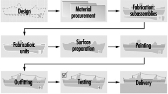
Newport News Shipbuilding
The basic component of ship building is steel plate. The plates are cut, shaped, bent or otherwise manufactured to the desired configuration specified by the design (see figure 2 and figure 3). Typically the plates are cut by an automatic flame cutting process to various shapes. These shapes may be then welded together to form I and T beams and other structural members (see figure 4).
Figure 2. Automatic flame cutting of steel plate in fabrication shop.
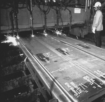
Eileen Mirsch
Figure 3. Bending of steel sheet.
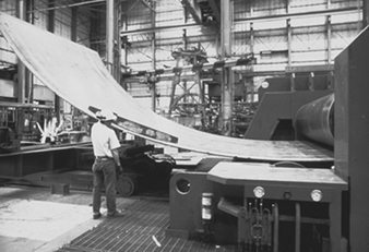
Newport News Shipbuilding
Figure 4. Welded steel plate forming part of a ship's hull.
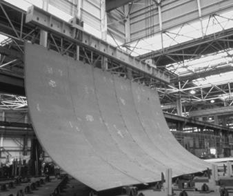
Newport News Shipbuilding
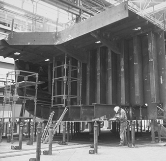
The plates are then sent to fabrication shops, where they are joined into various units and subassemblies (see figure 5). At this juncture, piping, electrical and other utility systems are assembled and integrated into the units. The units are assembled using automatic or manual welding or a combination of the two. Several types of welding processes are employed. The most common is stick welding, in which a consumable electrode is used to join the steel. Other welding processes use inert gas shielded arcs and even non-consumable electrodes.
Figure 5. Working on a ship subassembly
Newport News Shipbuilding
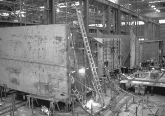
The units or subassemblies are usually then transferred to an open-air platen or lay down area where erection, or joining of assemblies, occurs to form even larger units or blocks (see figure 6) Here, additional welding and fitting occurs. Further, the units and welds must undergo quality-control inspections and testing such as radiography, ultrasonic and other destructive or non-destructive tests. Those welds found defective must be removed by grinding, arc-air grouping or chiseling and then replaced. At this stage the units are abrasive blasted to ensure proper profiling, and painted (see figure 7. Paint may be applied by brush, roller or spray gun. Spraying is most commonly utilized. The paints may be flammable or toxic or pose an environmental threat. Control of abrasive blasting and painting operations must be performed at this time.
Figure 6. Combining of ship subassemblies into larger blocks
Newport News Shipbuilding
Figure 7. Abrasive blasting of ship units prior to painting.
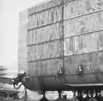
Judi Baldwin
The completed larger units are then moved to the graving dock, shipway or final assembly area. Here, the larger units are joined together to form the vessel (see figure 8) Again, much welding and fitting occur. Once the hull is structurally complete and watertight, the vessel is launched. This may involve sliding it into the water from the shipway on which it was constructed, flooding of the dock in which it was constructed or lowering the vessel into the water. Launchings are almost always accompanied by great celebration and fanfare.
Figure 8. Adding ship's bow to the rest of the vessel.
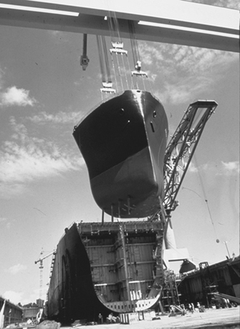
Newport News Shipbuilding
After the ship is launched, it enters the outfitting phase. A large amount of time and equipment are required. The work includes the fitting of cabling and piping, the furnishing of galleys and accommodations, insulation work, installation of electronic equipment and navigation aids and installation of propulsion and ancillary machinery. This work is performed by a wide variety of skilled trades.
After completion of the outfitting phase, the ship undergoes both dock and sea trials, during which all the ship’s systems are proved to be fully functional and operational. Finally, after all testing and associated repair work is performed, the ship is delivered to the customer.
Steel fabrication
A detailed discussion of the steel fabrication process follows. It is discussed in the context of cutting, welding and painting.
Cutting
The “assembly line” of the shipyard starts in the steel storage area. Here, large steel plates of various strengths, sizes, and thicknesses are stored and readied for fabrication. The steel is then blasted with abrasive and primed with a construction primer that preserves the steel during the various phases of construction. The steel plate then is transported to a fabrication facility. Here the steel plate is cut by automatic burners to the desired size (see figure 2). The resulting strips are then welded together to form the structural components of the vessel (figure 4).
Welding
The structural framework of most ships is constructed of various grades of mild and high-strength steel. Steel provides the formability, machinability and weldability required, combined with the strength needed for ocean-going vessels. Various grades of steel predominate in the construction of most ships, although aluminium and other nonferrous materials are used for some superstructures (e.g., deck-houses) and other specific areas within the ship. Other materials found on ships, like stainless steel, galvanized steel and copper-nickel alloy, are used for a variety of corrosion-resistance purposes and to improve structural integrity. However, nonferrous materials are used in far less quantity than steel. Shipboard systems (e.g., ventilation, combat, navigational and piping) are usually where the more “exotic” materials are used. These materials are required to perform a wide variety of functions, including the ship propulsion systems, back-up power, kitchens, pump stations for fuel transfer and combat systems.
Steel used for construction can be subdivided into three types: mild, high-strength and high-alloy steel. Mild steels have valuable properties and are easy to produce, purchase, form and weld. On the other hand, high-strength steels are mildly alloyed to provide mechanical properties that are superior to the mild steels. Extremely high-strength steels have been developed specifically for use in naval construction. In general, the high-strength and high-yield steels are called HY-80, HY-100 and HY-130. They have strength properties in excess of the commercial-grade high-strength steels. More complicated welding processes are necessary for high-strength steels in order to prevent deterioration of their properties. Specific weld rods are needed for high-strength steel, and weld joint heating (preheating) is usually required. A third general class of steels, the high-alloy steels, are made by including relatively large amounts of alloying elements such as nickel, chromium and manganese. These steels, which include stainless steels, have valuable corrosion-resistance properties and also require special welding processes.
Steel is an excellent material for shipbuilding purposes, and the choice of welding electrode is critical in all welding applications during construction. The standard goal is to obtain a weld with equivalent strength characteristics to that of the base metal. Since minor flaws are likely to occur in production welding, welds are often designed and welding electrodes chosen to produce welds with properties in excess of those of the base metal.
Aluminium has found increased application as a shipbuilding metal due to its high strength-to-weight ratio compared to steel. Although the use of aluminium for hulls has been limited, aluminium superstructures are becoming more common for both military and merchant ship construction. Vessels made solely from aluminium are primarily smaller-sized boats, such as fishing boats, pleasure boats, small passenger boats, gunboats and hydrofoils. The aluminium used for shipbuilding and repair is generally alloyed with manganese, magnesium, silicon and/or zinc. These alloys offer good strength, corrosion resistance and weldability.
Shipyard welding processes, or more specifically fusion welding, is performed at nearly every location in the shipyard environment. The process involves joining metals by bringing adjoining surfaces to extremely high temperatures to be fused together with a molten filler material. A heat source is used to heat the edges of the joint, permitting them to fuse with molten weld fill metal (electrode, wire or rod). The required heat is usually generated by an electric arc or a gas flame. Shipyards choose the type of welding process based on customer specifications, production rates and a variety of operating constraints including government regulations. Standards for military vessels are usually more stringent than commercial vessels.
An important factor with respect to the fusion-welding processes is arc shielding to protect the weld pool. The temperature of the weld pool is substantially higher than the adjoining metal’s melting point. At extremely high temperatures, a reaction with oxygen and nitrogen in the atmosphere is rapid and has negative effects on the weld strength. Should oxygen and nitrogen from the atmosphere become trapped within the weld metal and molten rod, embrittlement of the weld area will occur. To protect against this weld impurity and ensure weld quality, shielding from the atmosphere is required. In most welding processes, shielding is accomplished by addition of a flux, a gas or a combination of the two. Where a flux material is used, gases generated by vaporization and chemical reaction at the electrode tip result in a combination of flux and gas shielding that protect the weld from nitrogen and oxygen entrapment. Shielding is discussed in the following sections, where specific welding processes are described.
In electric arc welding, a circuit is created between the work-piece and an electrode or wire. When the electrode or wire is held a short distance away from the work-piece, a high-temperature arc is created. This arc generates sufficient heat to melt the edges of the work-piece and the tip of the electrode or wire to produce a fusion-welding system. There are a number of electric arc welding processes suitable for use in shipbuilding. All processes require shielding of the weld area from the atmosphere. They may be subdivided into flux-shielded and gas-shielded processes.
Manufacturers of welding equipment and associated consumable and non-consumable products report that arc welding with consumable electrodes is the most universal welding process.
Shielded metal arc welding (SMAW). Flux-shielded electric arc welding processes are distinguished primarily by their manual or semi-automatic nature and the type of consumable electrode used. The SMAW process utilizes a consumable electrode (30.5 to 46 cm in length) with a dry flux coating, held in a holder and fed to the work-piece by the welder. The electrode consists of the solid metal filler rod core, made from either drawn or cast material covered with a sheath of metal powders. SMAW is also frequently referred to as “stick welding” and “arc welding”. The electrode metal is surrounded by flux that melts as welding progresses, covering the deposited molten metal with slag and enveloping the immediate area in an atmosphere of protective gas. Manual SMAW may be used for down hand (flat), horizontal, vertical and overhead welding. SMAW processes may also be used semi-automatically through the use of a gravity welding machine. Gravity machines use the weight of the electrode and holder to produce travel along the work-piece.
Submerged arc welding (SAW) is another flux-shielded electric arc welding process used in many shipyards. In this process, a blanket of granulated flux is deposited on the work-piece, followed by a consumable bare metal wire electrode. Generally, the electrode serves as the filler material, although in some cases metal granules are added to the flux. The arc, submerged in the blanket of flux, melts the flux to produce a protective insulated molten shield in the weld zone. High heat concentration permits heavy weld deposits at relatively high speeds. After welding, the molten metal is protected by a layer of fused flux, which is subsequently removed and may be recovered. Submerged arc welding must be performed down hand and is ideally suited to butt welding plates together on panel lines, platen areas and erection areas. The SAW process is generally fully automatic, with equipment mounted on a moving carriage or self-propelled platform on top of the work-piece. Since the SAW process is primarily automatic, a good portion of time is spent aligning the weld joint with the machine. Similarly, since the SAW arc operates under a covering of granulated flux, the fume generation rate (FGR) or fume formation rate (FFR) is low and will remain constant under various operating conditions provided that there is adequate flux cover.
Gas metal arc welding (GMAW). Another major category of electric arc welding comprises the gas-shielded processes. These processes generally use bare wire electrodes with an externally supplied shielding gas which may be inert, active or a combination of the two. GMAW, also commonly referred to as metal inert gas (MIG) welding, uses a consumable, automatically fed, small-diameter wire electrode and gas shielding. GMAW is the answer to a long-sought method of being able to weld continuously without the interruption of changing electrodes. An automatic wire feeder is required. A wire spooling system provides an electrode/wire filler rate that is at a constant speed, or the speed fluctuates with a voltage sensor. At the point where the electrode meets the weld arc, argon or helium being used as the shielding gas is supplied by the welding gun. It was found that for welding steel, a combination of CO2 and/or an inert gas could be used. Often, a combination of the gases is used to optimize cost and weld quality.
Gas tungsten arc welding (GTAW). Another type of gas-shielded welding process is gas tungsten arc welding, sometimes referred to as tungsten inert gas (TIG) welding or the trade name Heliarc, because helium was initially used as the shielding gas. This was the first of the “new” welding processes, following stick welding by about 25 years. The arc is generated between the work-piece and a tungsten electrode, which is not consumed. An inert gas, usually argon or helium, provides the shielding and provides for a clean, low-fume process. Also, the GTAW process arc does not transfer the filler metal, but simply melts the material and the wire, resulting in a cleaner weld. GTAW is most often employed in shipyards for welding aluminium, sheet metal and small-diameter pipes and tubes, or to deposit the first pass on a multi-pass weld in larger pipe and fittings.
Flux core arc welding (FCAW) uses equipment similar to GMAW in that the wire is fed continuously to the arc. The main difference is that the FCAW electrode is a tubular electrode wire with a flux core centre that helps with localized shielding in the welding environment. Some flux cored wire provides adequate shielding with the flux core alone. However, many FCAW processes used in the shipbuilding environment require the addition of gas shielding for the quality requirements of the shipbuilding industry.
The FCAW process provides a high-quality weld with higher production rates and welder efficiency than the traditional SMAW process. The FCAW process allows for a full range of production requirements, such as overhead and vertical welding. FCAW electrodes tend to be a little more expensive than SMAW materials, although in many cases increased quality and productivity are worth the investment.
Plasma-arc welding (PAW). The last of the shielded gas welding processes is plasma-metal inert-gas welding. PAW is very similar to the GTAW process except that the arc is forced to pass through a restriction before reaching the work-piece. The result is a jet stream of intensely hot and fast-moving plasma. The plasma is an ionizing stream of gas that carries the arc, which is generated by constricting the arc to pass through a small orifice in the torch. PAW results in a more concentrated, high-temperature arc, and this permits faster welding. Aside from the use of the orifice to accelerate the gas, PAW is identical to GTAW, using a non-consumable tungsten electrode and an inert gas shield. PAW is generally manual and has minimal use in shipbuilding, although it is sometimes used for flame spraying applications. It is used primarily for steel cutting in the shipbuilding environment (see figure 9).
Figure 9. Underwater Plasma-arc cutting of steel plate

Caroline Kiehner
Gas welding, brazing and soldering. Gas welding employs heat generated by the burning of a gas fuel and generally uses a filler rod for the metal deposited. The most common fuel is acetylene, used in combination with oxygen (oxyacetylene gas welding). A hand-held torch directs the flame to the work-piece while simultaneously melting filler metal which is deposited on the joint. The surface of the work-piece melts to form a molten puddle, with filler material used to fill gaps or grooves. The molten metal, mainly filler metal, solidifies as the torch progresses along the work-piece. Gas welding is comparatively slow and not suitable for use with automatic or semiautomatic equipment. Consequently, it is rarely used for normal production welding in shipyards. The equipment is small and portable, and it can be useful for welding thin plate (up to about 7 mm), as well as for small-diameter pipe, heating, ventilating and air conditioning (HVAC) trunks (sheet metal), electrical cable ways and for brazing or soldering. Identical or similar equipment is used for cutting.
Soldering and brazing are techniques for bonding two metal surfaces without melting the parent metal. A liquid is made to flow into and fill the space between the two surfaces and then solidify. If the temperature of the filler metal is below 450ºC, the process is called soldering; if it is above 450ºC, the process is called brazing. Soldering is commonly done using heat from a soldering iron, flame, electrical resistance or induction. Brazing uses the heat from a flame, resistance or induction. Brazing may also be done by dipping parts in a bath. Soldered and brazed joints do not have the strength properties of welded joints. Consequently, brazing and soldering find limited application in shipbuilding and repair, except for primarily small-diameter pipe joints, sheet metal fabrication, small and infrequent joiner work and maintenance functions.
Other welding processes. There are additional types of welding that may be used in the shipyard environment in small quantities for a variety of reasons. Electroslag welding transfers heat through molten slag, which melts the work-piece and the filler metal. Although the equipment used is similar to that used for electric arc welding, the slag is maintained in a molten state by its resistance to the current passing between the electrode and the work-piece. Therefore, it is a form of electric resistance welding. Often a cooled backing plate is used behind the work-piece to contain the molten pool. Electrogas welding employs a similar setup but uses a flux-coated electrode and CO2 gas shielding. Both of these processes are very efficient for automatically making vertical butt welds and are highly advantageous for thicker plate. These techniques are expected to receive considerably wider application in shipbuilding.
Thermite welding is a process that uses superheated liquid metal to melt the work-piece and provided filler metal. The liquid metal results from a chemical reaction between a melt oxide and aluminium. The liquid metal is poured into the cavity to be welded, and the cavity is surrounded by a sand mould. Thermite welding is somewhat similar to casting and is primarily used to repair castings and forgings or to weld large structural sections such as a stern frame.
Laser welding is a new technology which uses a laser beam to melt and join the work-piece. Although the feasibility of laser welding has been proven, cost has prevented its commercial application to date. The potential for efficient, high-quality welding may make laser welding an important technique for shipbuilding in the future.
Another relatively new welding technique is called electron beam welding. The weld is made by firing a stream of electrons through an orifice to the work-piece, which is surrounded by an inert gas. Electron beam welding does not depend on thermal conductivity of the material to melt the metal. Consequently, both lower energy requirements and reduced metallurgical effects on the steel are significant benefits of this technique. As with laser welding, high cost is a major problem.
Stud welding is a form of electric arc welding in which the stud itself is the electrode. A stud welding gun holds the stud while the arc is formed and the plate and stud end become molten. The gun then forces the stud against the plate and the stud is welded to the plate. Shielding is obtained by the use of a ceramic ferrule surrounding the stud. Stud welding is a semi-automatic process commonly used in shipbuilding to facilitate installation of non-metallic materials, such as insulation, to steel surfaces.
Painting and finish coating
Painting is performed at almost every location in the shipyard. The nature of shipbuilding and repair requires several types of paints to be used for various applications. Paint types range from water-based coatings to high-performance epoxy coatings. The type of paint needed for a certain application depends on the environment to which the coating will be exposed. Paint application equipment ranges from simple brushes and rollers to airless sprayers and automatic machines. In general, shipboard paint requirements exist in the following areas:
- underwater (hull bottom)
- waterline
- topside superstructures
- internal spaces and tanks
- weather decks
- loose equipment.
Many different painting systems exist for each of these locations, but navy ships may require a specific type of paint for every application through a military specification (Mil-spec). There are many considerations when choosing paints, including environmental conditions, severity of environmental exposure, drying and curing times, applications equipment and procedures. Many shipyards have specific facilities and yard locations where painting occurs. Enclosed facilities are expensive, but yield higher quality and efficiency. Open-air painting generally has a lower transfer efficiency and is limited to good weather conditions.
Shipyard paint coating systems. Paints are used for a variety of purposes on a variety of locations on the ships. No one paint can perform all of the desired functions (e.g., rust prevention, anti-fouling and alkaline resistance). Paints are made up of three main ingredients: pigment, a vehicle and a solvent. Pigments are small particles that generally determine the colour as well as the many properties associated with the coating. Examples of pigments are zinc oxide, talc, carbon, coal tar, lead, mica, aluminium and zinc dust. The vehicle can be thought of as the glue that holds the paint pigments together. Many paints are referred to by their binder type (e.g., epoxy, alkyd, urethane, vinyl, phenolic). The binder is also very important for determining the coating’s performance characteristics (e.g., flexibility, chemical resistance, durability, finish). The solvent is added to thin the paint and allow for flowing application to surfaces. The solvent portion of the paint evaporates when the paint dries. Some typical solvents include acetone, mineral spirits, xylene, methyl ethyl ketone and water. Anticorrosive and anti-fouling paints are typically used on ships’ hulls and are the main two types of paint used in the shipbuilding industry. The anticorrosive paints are either vinyl-, lacquer-, urethane- or newer epoxy-based coating systems. The epoxy systems are now very popular and exhibit all of the qualities which the marine environment requires. Anti-fouling paints are used to prevent the growth and attachment of marine organisms on the hulls of vessels. Copper-based paints are widely used as anti-fouling paints. These paints release minute quantities of toxic substances in the immediate vicinity of the vessel’s hull. To achieve different colours, lampblack, red iron oxide or titanium dioxide may be added to the paint.
Shipyard primer coatings. The first coating system applied to raw steel sheets and parts is generally preconstruction primer, which is sometimes referred to as “shop primer”. This coat is important for maintaining the condition of the part throughout the construction process. Preconstruction priming is performed on steel plates, shapes, sections of piping and ventilation ducting. Shop primer has two important functions: (1) preserving the steel material for the final product and (2) aiding in the productivity of construction. Most preconstruction primers are zinc rich, with organic or inorganic binders. Zinc silicates are predominant among the inorganic zinc primers. Zinc coating systems protect coatings in much the same manner as galvanizing. If zinc is coated on steel, oxygen will react with the zinc to form zinc oxide, which forms a tight layer that does not allow water and air to come into contact with the steel.
Paint-applying equipment. There are many types of paint application equipment used in the shipbuilding industry. Two common methods used are compressed-air and airless sprayers. Compressed-air systems spray both air and paint, which causes some paint to atomize (dry) quickly prior to reaching the intended surface. The transfer efficiency of air-assisted spray systems can vary from 65 to 80%. This low transfer efficiency is due mainly to overspray, drift and the air sprayer’s inefficiencies; these sprayers are becoming obsolete because of their low transfer ability.
The most widely used form of paint application in the shipbuilding industry is the airless sprayer. The airless sprayer is a system which simply compresses paint in a hydraulic line and has a spray nozzle at the end; hydrostatic pressure, instead of air pressure, conveys the paint. To reduce the amount of overspray and spillage, shipyards are maximizing the use of airless paint sprayers. Airless sprayers are much cleaner to operate and have fewer leaking problems than compressed-air sprayers because the system requires less pressure. Airless sprayers have close to 90% transfer efficiency, depending on the conditions. A new technology which can be added to the airless sprayer is called high volume, low pressure (HVLP). HVLP offers an even higher transfer efficiency, in certain conditions. Measurements of transfer efficiency are estimates and include allowances for drips and spills which can occur when painting.
Thermal spray, also known as metal or flame spray, is the application of aluminium or zinc coatings to steel for long-term corrosion protection. This coating process is used on a wide variety of commercial and military applications. It is significantly different from conventional coating practices due to its specialized equipment and relatively slow production rates. There are two basic types of thermal coating machines: combustion wire and arc spray. The combustion wire type consists of combustible gases and a flame system with a wire feed controller. The combustible gases melt the material to be sprayed onto the parts. The electric arc spray machine instead uses a power supply arc to melt the flame sprayed material. This system includes an air-compression and filtration system, a power arc supply and controller and an arc flame spray gun. The surface must be properly prepared for proper adhesion of flame sprayed materials. The most common surface preparation technique is air blasting with fine grit (e.g., aluminium oxide).
The initial cost of thermal spray is usually high compared to painting, although when the lifecycle is taken into account, thermal spray becomes more economically attractive. Many shipyards have their own thermal spray machines, and other shipyards will subcontract their thermal coating work. Thermal spray can be done in a shop or on board the ship.
Painting practices and methods. Painting is performed in nearly every area in the shipyard, from the initial priming of the steel to the final paint detailing of the ship. Methods for painting vary greatly from process to process. Mixing of paint is performed both manually and mechanically and is usually done in an area surrounded by berms or secondary containment pallets; some of these are covered areas. Outdoor as well as indoor painting occurs in the shipyard. Shrouding fences, made of steel, plastic or fabric, are frequently used to help contain paint overspray or to block the wind and catch paint particles. New technology will aid in reducing the amount of airborne particles. Reducing the amount of overspray also reduces the amount of paint used and thus saves the shipyard money.
Surface preparation and painting areas in the shipyard
To illustrate painting and surface preparation practices in the shipbuilding and repair industry, practices can be generically described in five main areas. The following five areas help to illustrate how painting occurs in the shipyard.
Hull painting. Hull painting occurs on both repair ships and new construction ships. Hull surface preparation and painting on repair ships is normally performed when the ship is fully drydocked (i.e., on the graving dock of a floating drydock). For new construction, the hull is prepared and painted at a building position using one of the techniques discussed above. Air and/or water blasting with mineral grit are the most common types of surface preparation for hulls. Surface preparation involves blasting the surface from platforms or lifts. Similarly, paint is applied using sprayers and high-reach equipment such as man-lifts, scissor lifts or portable scaffolding. Hull painting systems vary in the number of coats required.
Superstructure painting. The superstructure of the ship consists of the exposed decks, deck houses and other structures above the main deck. In many cases, scaffolding will be used on board the ship to reach antennas, houses and other superstructures. If it is likely that paint or blast material will fall into adjacent waters, shrouding is put into place. On ships being repaired, the ship’s superstructure is painted mostly while berthed. The surface is prepared using either hand tools or air-nozzle blasting. Once the surface is prepared and the associated surface materials and grit are cleaned up and disposed of, then painting can commence. Paint systems usually are applied with airless paint sprayers. The painters access the superstructures with existing scaffolding, ladders and various lifting equipment that was used during surface preparation. The shrouding system (if applicable) that was used for blast containment will stay in place to help contain any paint overspray.
Interior tank and compartment painting. Tanks and compartments on board ships must be coated and re-coated to maintain the longevity of the ship. Re-coating of repair ship tanks requires a large amount of surface preparation prior to painting. The majority of the tanks are at the bottom of the ship (e.g., ballast tanks, bilges, fuel tanks). The tanks are prepared for paint by using solvents and detergents to remove grease and oil build-up. The wastewater developed during tank cleaning must be properly treated and disposed of. After the tanks are dried, they are abrasive blasted. During the blasting operation, the tank must have recirculating air and the grit must be vacuumed out. The vacuum systems used are either of a liquid ring or rotary screw type. These vacuums must be very powerful to remove the grit from the tank. The vacuum systems and ventilation systems are generally located on the dock’s surface, and access to the tanks is through holes in the hull. Once the surface is blasted and the grit is removed, painting can begin. Adequate ventilation and respirators are required for all tank and compartment surface preparation and painting (i.e., in enclosed or confined spaces).
Paint surface preparation as stages of construction. Once the blocks, or multiple units, leave the assembly area, they are frequently transported to a blast area where the entire block is prepared for paint. At this point, the block is usually blasted back down to bare metal (i.e., the construction primer is removed) (see figure 7 ). The most frequent method for block surface preparation is air-nozzle blasting. The next stage is the paint application stage. Painters generally use airless spray equipment on access platforms. Once the block’s coating system has been applied, the block is transported to the on-block stage, where outfitting materials are installed.
Small parts painting areas. Many parts comprising a ship need to have a coating system applied to them prior to installation. For example, piping spools, vent ducting, foundations and doors are painted before they are installed on block. Small parts are generally prepared for paint in a designated area of the shipyard. Small parts painting can occur in another designated location in the shipyard that best matches production needs. Some small parts are painted in the various shops, while others are painted in a standard location operated by the paint department.
Surface preparation and painting on block and on board
Final painting of the ship occurs on board, and touch-up painting will frequently occur on block (see figure 10). On-block touch-up painting occurs for several reasons. In some cases, paint systems are damaged on block and need to be resurfaced, or perhaps the wrong paint system was applied and needs to be replaced. On-block painting involves using portable blasting and painting equipment throughout the on-block outfitting areas. On-board painting involves preparing and painting the interface sections between the construction blocks and repainting areas damaged by welding, rework, on-board outfitting and other processes. The surfaces can be prepared by hand tools, sanding, brushing, solvent cleaning or any of the other surface preparation techniques. Paint is applied with portable airless sprayers, rollers and brushes.
Figure 10. Touch-up painting on a ship's hull.
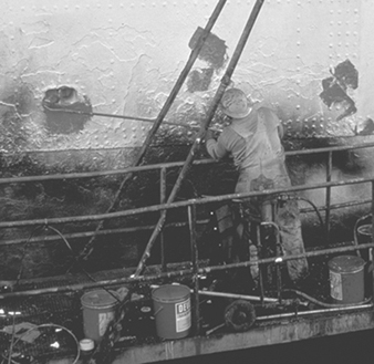
Newport News Shipbuilding
Outfitting
Pre-erection outfitting of construction blocks is the current shipbuilding method used by all competitive shipbuilders worldwide. Outfitting is the process of installing parts and various subassemblies (e.g., piping systems, ventilation equipment, electrical components) on the block prior to joining the blocks together at erections. The outfitting of blocks throughout the shipyard lends itself to forming an assembly line approach to shipbuilding.
Outfitting at each stage of construction is planned to make the process flow smoothly throughout the shipyard. For simplicity, outfitting can be divided into three main stages of construction once the steel structure of the block has been assembled:
- unit outfitting
- on-block outfitting
- on-board outfitting.
Unit outfitting is the stage where fittings, parts, foundations, machinery and other outfitting materials are assembled independent of the hull block (i.e., units are assembled separate from steel structural blocks). Unit outfitting allows workers to assemble shipboard components and systems on the ground, where they have easy access to the machinery and workshops. Units are installed at either the on-board or the on-block stage of construction. Units come in varying sizes, shapes and complexities. In some cases, units are as simple as a fan motor connected to a plenum and coil. Large, complex units are mainly composed of components in machinery spaces, boilers, pump rooms and other complex areas of the ship. Unit outfitting involves assembling piping spools and other components together, then connecting the components into units. Machinery spaces are areas on the ship where machinery is located (e.g., engine rooms, pump stations and generators) and outfitting there is intensive. Outfitting units on the ground increases safety and efficiency by reducing the work hours that would otherwise be allocated to on-block or on-board work in more confined spaces where conditions are more difficult.
On-block outfitting is the stage of construction where most of the outfitting material is installed onto the blocks. Outfitting materials installed on block consist of ventilation systems, piping systems, doors, lights, ladders, railings, electrical assemblies and so on. Many units are also installed at the on-block stage. Throughout the on-block outfitting stage, the block can be lifted, rotated and moved to efficiently facilitate installing outfitting materials on the ceilings, walls and floors. All of the shops and services in the shipyard must be in communication at the on-block stage to ensure that materials are installed at the right time and place.
On-board outfitting is performed after the blocks are lifted onto the ship under construction (i.e., after erection). At this time, the ship is either at a building position (building ways or building dock), or the ship could be berthed at pierside. The blocks are already outfitted to a large extent, although much more work is still needed before the ship is ready to operate. On-board outfitting involves the process of installing large units and blocks on board the ship. Installation includes lifting the large blocks and units on board the new ship and welding or bolting them into place. On-board outfitting also involves connecting the shipboard systems together (i.e., piping system, ventilation system and electrical system). All of the wiring systems are pulled throughout the ship at the on-board stage.
Testing
The operation and test stage of construction assesses the functionality of installed components and systems. At this stage, systems are operated, inspected and tested. If the systems fail the tests for any reason, the system must be repaired and retested until it is fully operational. All piping systems on board the ship are pressurized to locate leaks that may exist in the system. Tanks also need structural testing, which is accomplished by filling the tanks with fluids (i.e., salt water or fresh water) and inspecting for structural stability. Ventilation, electrical and many other systems are tested. Most system testing and operations occur while the ship is docked at pierside. However, there is an increasing trend to perform testing at earlier stages of construction (e.g., preliminary testing in the production shops). Performing tests at earlier stages of construction makes it easier to fix failures because of the increased accessibility to the systems, although complete systems tests will always need be done on board. Once all preliminary pierside testing is performed, the ship is sent to sea for a series of fully operational tests and sea trials before the ship is delivered to its owner.
Ship Repair
Steel ship repair practices and processes
Ship repair generally includes all ship conversions, overhauls, maintenance programmes, major damage repairs and minor equipment repairs. Ship repair is a very important part of the shipping and shipbuilding industry. Approximately 25% of the labour force in most private shipbuilding shipyards does repair and conversion work. Currently there are many ships that need updating and/or conversions to meet safety and environmental requirements. With fleets worldwide becoming old and inefficient, and with the high cost of new ships, the situation is putting a strain on shipping companies. In general, conversion and repair work in US shipyards is more profitable than new construction. In new-construction shipyards, repair contracts, overhauls and conversions also help to stabilize the workforce during times of limited new construction, and new construction augments the repair labour workload. The ship repair process is much like the new construction process, except that it is generally on a smaller scale and is performed at a faster pace. The repair process requires a more timely coordination and an aggressive bidding process for ship repair contracts. Repair work customers are generally the navy, commercial ship owners and other marine structure owners.
The customer usually provides contract specifications, drawings and standard items. Contracts can be firm fixed price (FFP), firm fixed price award fee (FFPAF), cost plus fixed fee (CPFF), cost plus award fee (CPAF) or urgent repair contracts. The process starts in the marketing area when the shipyard is asked for a request for proposal (RFP) or an invitation for bid (IFB). The lowest price usually wins an IFB contract, while a RFP award can be based on factors other than price. The repair estimating group prepares the cost estimate and the proposal for the repair contract. Bid estimates generally include worker-hours and wage rates, materials, overhead, special service costs, subcontractor dollars, overtime and shift premiums, other fees, facilities cost of money and, based on these, the estimated price of the contract. Once the contract is awarded, a production plan must be developed.
Repair planning, engineering and production
Although some preliminary planning is performed at the proposal stage of the contract, much work is still needed to plan and execute the contract in a timely manner. The following steps should be accomplished: read and understand all contract specifications, categorize the work, integrate the work into a logical production plan and determine the critical path. Planning, engineering, materials, subcontracts and repair production departments must work closely together to perform the repair in the most timely and cost-effective manner. Prefabrication of piping, ventilation, electrical and other machinery is performed, in many cases, prior to the ship’s arrival. Pre-outfitting and prepackaging of repair units takes cooperation with the production shops to perform work in a timely manner.
Common types of repair work
Ships are similar to other types of machinery in that they require frequent maintenance and, sometimes, complete overhauls to remain operational. Many shipyards have maintenance contracts with shipping companies, ships and/or ship classes that identify frequent maintenance work. Examples of maintenance and repair duties include:
- blasting and repainting the ship’s hull, freeboard, superstructure, interior tanks and work areas
- major machinery rebuilding and installation (e.g., diesel engines, turbines, generators and pump stations)
- systems overhauls, maintenance and installation (e.g., flushing, testing and installation of a piping system)
- new system installation, either adding new equipment or replacing systems that are outdated (e.g., navigational systems, combat systems, communication systems or updated piping systems)
- propeller and rudder repairs, modification and alignment
- creation of new machinery spaces on the ship (e.g., cut-out of existing steel structure and adding new walls, stiffeners, vertical supports and webbing).
In many cases, repair contracts are an emergency situation with very little warning, which makes ship repair a fast moving and unpredictable environment. Normal repair ships will stay in the shipyard from 3 days to 2 months, while major repairs and conversions can last more than a year
Large repairs and conversion projects
Large repair contracts and major conversions are common in the ship repair industry. Most of these large repair contracts are performed by shipyards that have the ability to construct ships, although some primarily repair yards will perform extensive repairs and conversions.
Examples of major repair contracts are as follows:
- conversion of supply ships to hospital ships
- cutting a ship in half and installing a new section to lengthen the ship (see figure 11)
- replacing segments of a ship that has run aground (see figure 12)
- complete rip-out, structural reconfiguration and outfitting of combat systems
- major remodelling of ship’s interior or exterior (e.g., complete overhauls of passenger cruise ships).
Most major repairs and conversions require a large planning, engineering and production effort. In many cases, a large quantity of steel work will need to be accomplished (e.g., major cut-out of existing ship structure and installation of new configurations). These projects can be divided into four major stages: removal, building new structure, equipment installation and testing. Subcontractors are required for most major and minor repairs and conversions. The subcontractors provide expertise in certain areas and help to even the workload in the shipyard.
Figure 11. Cutting a ship in half in order to install a new section.
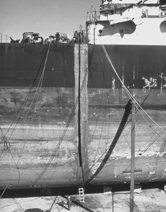
Newport News Shipbuilding
Figure 12. Replacing the prow of a ship that ran aground.

Newport News Shipbuilding
Some of the work that subcontractors perform are as follows:
-
support of ship repair
-
major combat systems installations (technical)
-
boiler re-tubing and rebuilding
-
air compressor overhauls
-
asbestos removal and disposal
-
tank cleaning
-
blasting and painting
-
pump system overhauls
-
small structural fabrication
-
winch overhauls
-
main steam system modifications
-
system fabrications (i.e., piping, ventilation, foundations and so on).
As with new construction, all installed systems must be tested and operational before the ship is returned to its owner. Testing requirements generally originate from the contract, although other sources of testing requirements do exist. The tests must be scheduled, tracked for proper completion and monitored by the proper groups (shipyard internal quality, vessel operation, government agencies, shipowners and so on). Once systems are in place and properly tested, the area, compartment and/or system can be considered sold to the ship (i.e., completed).
There are many similarities between new construction and repair processes. The primary similarities are that they both use the application of essentially the same manufacturing practices, processes, facilities and support shops. Ship repair and new construction work require highly skilled labour because many of the operations have limited potential for automation (especially ship repair). Both require excellent planning, engineering and interdepartmental communications. The repair process flow is generally as follows: estimate, plan and engineer the job; rip-out work; refitting of steel structures; repair production; test and trials; and deliver the ship. In many ways the ship repair process is similar to shipbuilding, although new construction requires a greater amount of organization because of the size of the workforce, size of the workload, number of parts and the complexity of the communications (i.e., production plans and schedules) surrounding the shipbuilding work flow.
Hazards and Precautions
Shipbuilding and repair is one of the most hazardous industries. Work must be done in a variety of highly hazardous situations, such as confined spaces and considerable heights. Much manual work is performed involving heavy equipment and material. Since the work is so interrelated, the results of one process may endanger personnel involved in another process. In addition, a great portion of work is performed out-of-doors, and the effects of weather extremes can cause or aggravate hazardous conditions. Additionally, a number of chemicals, paints, solvents and coatings must be used, which may pose significant risks to employees.
Health hazards
Chemical hazards which pose health risks to employees in shipyards include:
- dusts from abrasive blasting operations
- exposure to asbestos and mineral fibres in insulation work
- vapours and spray mists from paints, coatings, solvents and thinners
- fumes from various welding, burning, soldering and brazing operations
- exposure to gases used in various welding, burning and heating processes
- exposure to specific toxic chemicals in epoxy resins, organo-tin and copper anti-fouling paints, lead paint, oils, greases, pigments and the like.
Physical hazards due to the manual nature of the work include:
- temperature and weather extremes associated with work performed out-of-doors
- electrical hazards
- ergonomic-related problems caused by repetitive handling of large and bulky materials
- ionizing and non-ionizing radiation
- noise and vibration
- oxygen deficiency potential and other confined space hazards associated with tanks, double bottoms and so on
- falls and trips from work on the same level as well as work from great heights.
Preventive measures
Although shipbuilding and repair is a very hazardous industry, the risks to personnel by these hazards can and should be minimized. The basis for hazard reduction is a well-founded health and safety programme that is rooted in a good partnership between management and the trade unions or employees. There are a number of approaches that can be utilized to prevent or minimize hazards in shipyards once they are identified. These approaches may be broadly divided into several strategies. Engineering controls are employed to eliminate or control hazards at their point of generation. These controls are the most desirable of the various types since they are most dependable:
-
Substitution or elimination. Where possible, processes that produce hazards or toxic materials should be eliminated or replaced with less hazardous processes or materials. This is the most effective form of control. An example is the use of non-carcinogenic materials instead of asbestos insulation. Another example is the use of hydraulic lifting tables for handling heavy materials, instead of manual lifting. Replacement of solvent-based paints with water-based coatings is frequently possible. Automation or robotics can be used to eliminate process hazards.
-
Isolation. Processes that are not amenable to substitution or elimination can sometimes be isolated from employees to minimize exposures. Frequently, sources of high noise can be relocated to place more distance between workers and the noise source, thus reducing exposure.
-
Enclosure. Processes or personnel can sometimes be enclosed to eliminate or reduce exposures. Operators of equipment can be provided enclosed booths to minimize exposure to noise, heat, cold or even chemical hazards. Processes may also be enclosed. Paint-spray booths and welding booths are examples of process enclosure that reduce exposures to potentially toxic materials.
-
Ventilation. Processes that produce toxic materials can be ventilated to capture the materials at their point of generation. This technique is used extensively in shipyards and boatyards, particularly to control welding fumes and gases, paint vapours and the like. Many fans and blowers are located on the decks of vessels and air is either exhausted from or blown into spaces to reduce exposure to hazards. Frequently fans are used in the blowing mode to direct fresh air into compartments to maintain acceptable oxygen levels.
Administrative controls are used to minimize exposures by administratively limiting the time spent by personnel in potentially hazardous situations. This is generally accomplished by rotating personnel from a relatively low hazard job to a higher hazard one. Although the aggregate amount of person-exposure time is not changed, exposure of each individual worker is reduced.
Administrative controls are not without their negative aspects. This technique requires additional training since workers must know both jobs and more workers are potentially exposed to a hazard. Also, since the number of personnel exposed to hazards has doubled from a legal standpoint, potential liabilities may be increased. However, administrative control can be an effective method if properly applied.
Personal protective controls. Shipyards must rely heavily on the various forms of personal protection. The nature of ship construction and repair does not lend itself to traditional engineering approaches. Ships are very confined spaces with limited access. A submarine under repair has 1 to 3 hatches that are .76 m in diameter, through which people and equipment must pass. The amount of ventilation tubing that can pass through is severely limited. Similarly, on large ships work is performed deep within the vessel, and although some ventilation may be smoked through the various levels to reach the desired operation, the amount is limited. Further, the fans pushing or pulling air through the vent tubing are generally located in fresh air, usually on a main deck, and they, too, have somewhat limited capacity.
In addition, ship construction and repair is not performed in an assembly line, but in separate work sites such that stationary engineering controls are impractical. Further, a ship may be under repair for a few days, and the extent to which engineering control may be utilized is again limited. Personal protective equipment is used extensively in these situations.
In shops, more extensive use may be made of traditional engineering control approaches. Most equipment and machinery in shops and assembly platens is very amenable to traditional guarding, ventilation and other engineering approaches. However, some personal protective equipment must be utilized in these situations as well.
A discussion of the various applications of personal protective equipment utilized in shipyards follows:
Welding, cutting and grinding. The basic process of constructing and repairing ships involves cutting, shaping and joining steel and other metals. In the process, metallic fumes, dusts and particulates are generated. Although ventilation can sometimes be utilized, more frequently welders must utilize respirators for protection from welding particulates and fumes. In addition, they must employ appropriate eye protection for ultraviolet and infrared illumination and other physical eye and face hazards. In order to provide protection from sparks and other forms of molten metal, the welder must be protected by welding gloves, long-sleeved clothing and other physical protection.
Abrasive blasting and painting. Much painting is performed in ship construction and repair. In many cases, the paints and coatings are specified by the ship’s owner. Prior to painting, the equipment must be blasted with an abrasive to a certain profile that ensures good adhesion and protection.
Abrasive blasting of small parts may be performed in a closed system such as a glove box. However, most large components are abrasive blasted manually. Some blasting is performed in the open air, some in large bays of a building or shop designated for this purpose and some inside the vessels or vessel sections themselves. In any case, personnel performing abrasive blasting must use full-body protection, hearing protection and air-fed respiratory protection. They must be provided with an adequate supply of breathable air (i.e., at least Grade D breathing air).
In some countries the use of crystalline silica has been banned. Its use is generally not recommended. If silica-containing materials are used in blasting, preventive protective measures must be taken.
After abrasive blasting, materials must be quickly painted in order to prevent “flash rusting” of the surface. Although mercury, arsenic and other very toxic metals are no longer used in paints, paints used in shipyards generally contain solvents as well as pigments such as zinc. Other paints are of the epoxy type. Painters who apply these coatings must be protected. Most painters must use a negative or positive pressure respirator for their protection, as well as full-body coveralls, gloves, shoe covers and eye protection. Sometimes painting must be performed in confined or enclosed spaces. In these cases, air-supplied respiratory protection and full-body protection must be used, and there must be an adequate, permit-requiring confined-spaces programme.
Overhead hazards. Shipyards have many cranes, and a large amount of overhead work is performed. Hard-hat protection is generally required in all production areas of shipyards.
Insulation work. Piping systems and other components must be insulated to maintain component temperature and reduce heat in the ship’s interior; in some cases, insulation is needed for noise reduction. In ship repair, existing insulation must be removed from piping to do repair work; in these cases, asbestos material is frequently encountered. In new work, fibreglass and mineral fibres are frequently used. In either case, appropriate respiratory protection and full-body protection must be worn.
Noise sources. Work in shipyards is notoriously noisy. Most processes involve working with metal; this typically produces noise levels above acceptable safe limits. Not all noise sources can be controlled to safe levels by utilizing engineering controls. Thus, personal protection must be used.
Foot hazards. Shipyards have a number of operations and processes that present hazards to the feet. It is often difficult and impractical to segregate the facility into foot hazard and non-foot hazard areas; safety shoes/boots are typically required for the entire production area of shipyards.
Eye hazards. There are many potential sources of hazards to the eyes in shipyards. Examples are various ultraviolet and infrared light hazards from welding arcs, physical hazards from various metal working dusts and particles, abrasive blasting grit, work with various pickling and metal baths, caustics and paint sprays. Due to the ubiquitous nature of these hazards, safety glasses are frequently required throughout the production areas of shipyards for practical and administrative simplicity. Special eye protection is required for specific individual processes.
Lead. Over the years, lead-based primers and coatings have been utilized extensively in ship construction. Although lead-containing paints and coatings are rarely used today, a significant amount of elemental lead is used in nuclear shipyards as a radiation shielding material. In addition, ship repair work often involves the removal of older coatings that frequently contain lead. In fact, repair work requires a great deal of sensitivity and concern for materials that have been applied or used previously. Work with lead requires full-body protection including coveralls, gloves, hat, shoe covers and respiratory protection.
Boat Building
In some ways boats can be thought of as relatively small ships in that many of the processes used to construct and repair boats are very similar to those used to construct and repair ships, only on a smaller scale. Generally, steel, wood and composites are chosen for construction of boat hulls.
Composites include, in general, such materials as fibre-reinforced metals, fibre-reinforced cement, reinforced concrete, fibre-reinforced plastics and glass-reinforced plastics (GRPs). Development during the early 1950s of hand lay-up methods employing cold-cure polyester resin with glass reinforcement led to a rapid expansion of GRP boat construction, from 4% in the 1950s to over 80% in the 1980s and even higher currently.
In vessels over 40 m or so in length, steel rather than wood is the main alternative to GRP. As hull size is reduced, the relative cost of steel construction increases, becoming generally uncompetitive for hulls under 20 m in length. The need for corrosion margin tends also to lead to excessive weight in small steel boats. For vessels over 40 m, however, the low cost of heavy welded steel construction is normally a decisive advantage. Unless imaginative design, improved materials and automated fabrication can bring about a substantial reduction in costs, however, glass- or fibre-reinforced plastics seem unlikely to become competitive with steel for construction of ships over about 40 m in length except where special requirements exist (e.g., for transportation of corrosive or cryogenic bulk cargo, where a nonmagnetic hull is required or where substantial weight saving is necessary for performance reasons).
GRPs are now employed in a very wide range of boat hull applications including speedboats, coastal and ocean-going yachts, work boats, pilot and passenger launches and fishing boats. Its success in fishing boats, where wood has been the traditional material, is attributable to:
-
competitive first cost, particularly where many hulls are built to the same design, enhanced by the increasing cost of wood and scarcity of skilled woodworkers
-
trouble-free performance and low maintenance costs resulting from leak-proof, rot-proof qualities of GRP hulls, their resistance to marine boring organisms and low cost of repair
-
the ease with which complex shapes, which may be required for hydrodynamic and structural purposes or for aesthetic reasons, can be fabricated.
Fabrication methods
The most common form of construction for shells, decks and bulkheads in large and small GRP hulls is single-skin laminate reinforced as necessary by stiffeners. Various methods of fabrication are employed in the construction of single-skin and sandwich hulls.
Contact moulding. By far the most common method of fabrication for single-skin GRP hulls of all sizes is contact moulding in an open or negative mould using cold-curing polyester resin and E-glass reinforcement.
The first step in the fabrication process is mould preparation. For hulls of small and moderate size, moulds are usually fabricated in GRP, in which case a positive plug, commonly of wooden construction finished in GRP, is first assembled, whose external surface accurately defines the required hull shape. Mould preparation is generally completed by wax polishing and application of a film of polyvinyl alcohol (PVA) or equivalent release agent. Laminating is usually started by application of pigmented gel coat of good-quality resin. Laminating is then continued, before the gel coat has fully cured, using one of the following processes:
-
Spray up. Glass fibre rovings or reinforcements are sprayed simultaneously with polyester resin, the latter being mixed with catalyst and accelerator at the spray gun.
-
Hand lay-up. Resin mixed with catalyst and accelerator is deposited liberally on the gel coat or on a previous ply of impregnated reinforcement by brush, roller-dispenser or spray gun.
The process outlined above can achieve efficient application of very heavy reinforcement (fabric of up to 4,000 g/m2 has been used successfully, although for large-scale production a fabric weight of 1,500 to 2,000 g/m2 has been preferred), giving a rapid laminating rate with low labour costs. A similar process can be applied for rapid lay-up of flat or nearly flat deck and bulkhead panels. Batch production of certain 49 m hulls, including installation of decks and bulkheads, has been achieved with a completion time of 10 weeks per hull.
Compression moulding. Compression moulding involves application of pressure, possibly accompanied by heat, to the surface of an uncured laminate, to increase fibre content and reduce voids by squeezing out excess resin and air.
Vacuum bag moulding. This process, which may be regarded as an elaboration of contact moulding, involves placing over the mould a flexible membrane, separated from the uncured laminate by a film of PVA, polythene or equivalent material, sealing the edges and evacuating the space under the membrane so that the laminate is subjected to a pressure of up to l bar. Curing may be speeded by placing the bagged component in an oven or employing a heated mould.
Autoclave moulding. Higher pressures (e.g., 5 to 15 bar) combined with elevated temperature, yielding increased fibre content and hence superior mechanical properties, may be achieved by carrying out the bag moulding process in an autoclave (pressurized oven).
Matched die moulding. The uncured moulding material, which in a large component such as a boat hull is likely to be a sprayed premix of resin and chopped-strand glass or a tailored preform of pre-impregnated glass fabric, is compressed between matched positive and negative moulds, usually of metallic construction, with application of heat if required. Because of the high first cost of moulds, this process is likely to be economical only for large production runs and is rarely used for boat hull fabrication.
Filament winding. Fabrication in this process is carried out by winding reinforcing fibres, in the form of a continuous roving which may be impregnated with resin just prior to winding (wet-winding) or may be pre-impregnated with partially cured resin (dry-winding), onto a mandrel which defines the internal geometry.
Sandwich construction. Sandwich hulls, decks and bulkheads may be fabricated by contact moulding, using room-temperature curing polyester resin, in much the same way as single-skin structures. The outer GRP skin is first laid up on the negative mould. Strips of core material are embedded on a layer of polyester or epoxy resin. Fabrication is then completed by laying up the internal GRP skin.
Polyester and epoxy resins. Unsaturated polyester resins are by far the most commonly used matrix materials for marine structural laminates. Their effectiveness follows from their moderate cost, ease of use within hand lay-up or spray-up fabrication processes and generally good performance in a marine environment. Three main types are available:
-
Orthophthalic polyester, made by a combination of maleic and phthalic anhydrides with a glycol (commonly propylene glycol), is the least expensive and most widely used matrix material for small boat construction.
-
Isophthalic polyester, containing isophthalic acid in place of phthalic anhydride, is more expensive, has somewhat superior mechanical properties and water resistance and is commonly specified for higher-performance boat construction and marine gel coats.
-
Bisphenol epoxy systems, in which phthalic acid or anhydride is partly or completely replaced by bisphenol A, offers (at substantially higher cost) much improved water and chemical resistance.
Safety and health hazards
Although many of the chemical, physical and biological hazards in shipbuilding are common to boat building, a primary concern is exposure to various solvent vapours and epoxy dusts from the boat manufacturing process. Uncontrolled exposure to these hazards may produce central nervous system disorders, liver and kidney damage, and sensitization reactions, respectively. The controls for these potential hazards are essentially the same as those described previously in the shipbuilding section—namely, engineering controls, administrative controls and personal protective controls.
Ergonomics and Standardization
Origins
Standardization in the field of ergonomics has a relatively short history. It started in the beginning of the 1970s when the first committees were founded on the national level (e.g., in Germany within the standardization institute DIN), and it continued on an international level after the foundation of the ISO (International Organization for Standardization) TC (Technical Committee) 159 “Ergonomics”, in 1975. In the meantime ergonomics standardization takes place on regional levels as well, for example, on the European level within the CEN (Commission européenne de normalisation), which established its TC 122 “Ergonomics” in 1987. The existence of the latter committee underscores the fact that one of the important reasons for establishing committees for the standardization of ergonomics knowledge and principles can be found in legal (and quasi-legal) regulations, especially with respect to safety and health, which require the application of ergonomics principles and findings in the design of products and work systems. National laws requiring the application of well-established ergonomics findings were the reason for the establishment of the German ergonomics committee in 1970, and European Directives, especially the Machinery Directive (relating to safety standards), were responsible for establishing an ergonomics committee on the European level. Since legal regulations usually are not, cannot and should not be very specific, the task of specifying which ergonomics principles and findings should be applied was given to or taken up by ergonomics standardization committees. Especially on the European level, it can be recognized that ergonomics standardization can contribute to the task of providing for broad and comparable conditions of machinery safety, thus removing barriers to the free trade of machinery within the continent itself.
Perspectives
Ergonomics standardization thus started with a strong protective, although preventive, perspective, with ergonomics standards being developed with the aim of protecting workers against adverse effects at different levels of health protection. Ergonomics standards were thus prepared with the following intentions in view:
- to ensure that assigned tasks do not exceed the limits of the performance capacities of the worker
- to prevent injury or any detrimental effects to the health of the worker whether permanent or transient, either in the short or in the long run, even if the tasks in question can be performed, if only for a short time, without negative effects
- to provide that tasks and working conditions will not lead to impairments, even if recuperation is possible with time.
International standardization, which was not so closely coupled to legislation, on the other hand, always also tried to open a perspective in the direction of producing standards which would go beyond the prevention of and protection against adverse effects (e.g., by specifying minimal/maximal values) and instead proactively provide for optimal working conditions to promote the well-being and personal development of the worker, as well as the effectiveness, efficiency, reliability and productivity of the work system.
This is a point where it becomes evident that ergonomics, and especially ergonomics standardization, has very distinct social and political dimensions. Whereas the protective approach with respect to safety and health is generally accepted and agreed upon among the parties involved (employers, unions, administration and ergonomics experts) for all levels of standardization, the proactive approach is not equally accepted by all parties in the same way. This might be due to the fact that, especially where legislation requires the application of ergonomics principles (and thus either explicitly or implicitly the application of ergonomics standards), some parties feel that such standards might limit their freedom of action or negotiation. Since international standards are less compelling (transferring them into the body of national standards is at the discretion of the national standardization committees) the proactive approach has been developed furthest at the international level of ergonomics standardization.
The fact that certain regulations would indeed restrict the discretion of those to whom they applied served to discourage standardization in certain areas, for example in connection with the European Directives under Article 118a of the Single European Act, relating to safety and health in the use and operation of machinery at the workplace, and in the design of work systems and workplace design. On the other hand, under the Directives issued under Article 100a, relating to safety and health in the design of machinery with regard to the free trade of this machinery within the European Union (EU), European ergonomics standardization is mandated by the European Commission.
From an ergonomics point of view, however, it is difficult to understand why ergonomics in the design of machinery should be different from that in the use and operation of machinery within a work system. It is thus to be hoped that the distinction will be given up in the future, since it seems to be more detrimental than beneficial to the development of a consistent body of ergonomics standards.
Types of Ergonomics Standards
The first international ergonomics standard to have been developed (based on a German DIN national standard) is ISO 6385, “Ergonomic principles in the design of work systems”, published in 1981. It is the basic standard of the ergonomics standards series and set the stage for the standards which followed by defining the basic concepts and stating the general principles of the ergonomic design of work systems, including tasks, tools, machinery, workstations, work space, work environment and work organization. This international standard, which is now undergoing revision, is a guideline standard, and as such provides guidelines to be followed. It does not, however, provide technical or physical specifications which have to be met. These can be found in a different type of standards, that is, specification standards, for example, those on anthropometry or thermal conditions. Both types of standards fulfil different functions. While guideline standards intend to show their users “what to do and how to do it” and indicate those principles that must or should be observed, for example, with respect to mental workload, specification standards provide users with detailed information about safety distances or measurement procedures, for example, that have to be met and where compliance with these prescriptions can be tested by specified procedures. This is not always possible with guideline standards, although despite their relative lack of specificity it can usually be demonstrated when and where guidelines have been violated. A subset of specification standards are “database” standards, which provide the user with relevant ergonomics data, for example, body dimensions.
CEN standards are classified as A-, B- and C-type standards, depending on their scope and field of application. A-type standards are general, basic standards which apply to all kinds of applications, B-type standards are specific for an area of application (which means that most of the ergonomics standards within the CEN will be of this type), and C-type standards are specific for a certain kind of machinery, for example, hand-held drilling machines.
Standardization Committees
Ergonomics standards, like other standards, are produced in the appropriate technical committees (TCs), their subcommittees (SCs) or working groups (WGs). For the ISO this is TC 159, for CEN it is TC 122, and on the national level, the respective national committees. Besides the ergonomics committees, ergonomics is also dealt with in TCs working on machine safety (e.g., CEN TC 114 and ISO TC 199) with which liaison and close cooperation is maintained. Liaisons are also established with other committees for which ergonomics might be of relevance. Responsibility for ergonomics standards, however, is reserved to the ergonomics committees themselves.
A number of other organizations are engaged in the production of ergonomics standards, such as the IEC (International Electrotechnical Commission); CENELEC, or the respective national committees in the electrotechnical field; CCITT (Comité consultative international des organisations téléphoniques et télégraphiques) or ETSI (European Telecommunication Standards Institute) in the field of telecommunications; ECMA (European Computer Manufacturers Association) in the field of computer systems; and CAMAC (Computer Assisted Measurement and Control Association) in the field of new technologies in manufacturing, to name only a few. With some of these the ergonomics committees do have liaisons in order to avoid duplication of work or inconsistent specifications; with some organizations (e.g., the IEC) even joint technical committees are established for cooperation in areas of mutual interest. With other committees, however, there is no coordination or cooperation at all. The main purpose of these committees is to produce (ergonomics) standards that are specific to their field of activity. Since the number of such organizations at the different levels is rather large, it becomes quite complicated (if not impossible) to carry out a complete overview of ergonomics standardization. The present review will therefore be restricted to ergonomics standardization in the international and European ergonomics committees.
Structure of Standardization Committees
Ergonomics standardization committees are quite similar to one another in structure. Usually one TC within a standardization organization is responsible for ergonomics. This committee (e.g., ISO TC 159) mainly has to do with decisions about what should be standardized (e.g., work items) and how to organize and coordinate the standardization within the committee, but usually no standards are prepared at this level. Below the TC level are other committees. For example, the ISO has subcommittees (SCs), which are responsible for a defined field of standardization: SC 1 for general ergonomic guiding principles, SC 3 for anthropometry and biomechanics, SC 4 for human-system interaction and SC 5 for the physical work environment. CEN TC 122 has working groups (WGs) below the TC level which are so constituted as to deal with specified fields within ergonomics standardization. SCs within ISO TC 159 operate as steering committees for their field of responsibility and do the first voting, but usually they do not also prepare standards. This is done in their WGs, which are composed of experts nominated by their national committees, whereas SC and TC meetings are attended by national delegations representing national points of view. Within the CEN, duties are not sharply distinguished at the WG level; WGs operate both as steering and production committees, although a good deal of work is accomplished in ad hoc groups, which are composed of members of the WG (nominated by their national committees) and established to prepare the drafts for a standard. WGs within an ISO SC are established to do the practical standardization work, that is, prepare drafts, work on comments, identify needs for standardization, and prepare proposals to the SC and TC, which will then take the appropriate decisions or actions.
Preparation of Ergonomics Standards
The preparation of ergonomics standards has changed quite markedly within the last years in view of the stronger emphasis now being placed on European and other international developments. In the beginning, national standards, which had been prepared by experts from one country in their national committee and agreed upon by the interested parties among the general public of that country in a specified voting procedure, were transferred as input to the responsible SC and WG of ISO TC 159, after a formal vote had been taken at the TC level that such an international standard should be prepared. The working group, composed of ergonomics experts (and experts from politically interested parties) from all participating member bodies (i.e., the national standardization organizations) of TC 159 who were willing to cooperate in this work project, would then work on any inputs and prepare a working draft (WD). After this draft proposal is agreed upon in the WG, it becomes a committee draft (CD), which is distributed to the member bodies of the SC for approval and comments. If the draft receives substantial support from the SC member bodies (i.e., if at least two-thirds vote in favour) and after comments by the national committees have been incorporated by the WG in the improved version, a Draft International Standard (DIS) is submitted for voting to all members of TC 159. If substantial support, at this step from the member bodies of the TC, is achieved (and perhaps after incorporating editorial changes), this version will then be published as an International Standard (IS) by the ISO. Voting of the member bodies at the TC and SC level is based on voting at the national level, and comments can be supplied through the member bodies by experts or interested parties in each country. The procedure is roughly equivalent in CEN TC 122, with the exception that there are no SCs below the TC level and that voting takes part with weighted votes (according to the size of the country) whereas within the ISO the rule is one country, one vote. If a draft fails at any step, and unless the WG decides that an agreeable revision cannot be achieved, it has to be revised and then has to pass through the voting procedure again.
International standards are then transferred into national standards if the national committees vote accordingly. By contrast, European Standards (ENs) have to be transferred into national standards by the CEN members and conflicting national standards have to be withdrawn. That means that harmonized ENs will be effective in all CEN countries (and, due to their influence on trade, will be relevant to manufacturers in all other countries who intend to sell goods to a customer in a CEN country).
ISO-CEN Cooperation
In order to avoid conflicting standards and duplication of work and to allow non-CEN members to take part in developments in the CEN, a cooperative agreement between the ISO and the CEN has been achieved (the so-called Vienna Agreement) which regulates the formalities and provides for a so-called parallel voting procedure, which allows the same drafts to be voted upon in the CEN and the ISO in parallel, if the responsible committees agree to do so. Among the ergonomics committees the tendency is quite clear: avoid duplication of work (manpower and financial resources are too limited), avoid conflicting specifications, and try to achieve a consistent body of ergonomics standards based on a division of labour. Whereas CEN TC 122 is bound by the decisions of the EU administration and gets mandated work items to stipulate the specifications of European directives, ISO TC 159 is free to standardize whatever it thinks necessary or appropriate in the field of ergonomics. This has led to shifts in the emphasis of both committees, with the CEN concentrating on machinery and safety-related topics and the ISO concentrating on areas where broader market interests than Europe are concerned (e.g., work with VDUs and control-room design for process and related industries); on areas where the operation of machinery is concerned, as in work system design; and on such areas as work environment and work organization as well. The intention, however, is to transfer work results from the CEN to the ISO, and vice versa, in order to build up a body of consistent ergonomics standards which in fact are effective all over the world.
The formal procedure of producing standards is still the same today. But since the emphasis has shifted more and more to the international or the European level, more and more activities are being transferred to these committees. Drafts are now usually worked out directly in these committees and are no longer based on existing national standards. After the decision has been made that a standard should be developed, work directly starts at one of these supranational levels, based on whatever input there may be available, sometimes starting from zero. This changes the role of the national ergonomics committees quite dramatically. While heretofore they formally developed their own national standards according to their national rules, they now have the task of observing and influencing standardization on the supranational levels—via the experts who work out the standards or via comments made at the different steps of voting (within the CEN, a national standardization project will be halted if a comparable project is being simultaneously worked on at the CEN level). This makes the task still more complicated, since this influence can only be exerted indirectly and since the preparation of ergonomics standards is not just a matter of pure science but a matter of bargaining, consensus and agreement (not least due to the political implications which the standard might have). This, of course, is one of the reasons why the process of producing an international or European ergonomics standard usually takes several years and why ergonomics standards cannot reflect the latest state of the art in ergonomics. International ergonomics standards thus have to be examined every five years, and, if necessary, undergo revision.
Fields of Ergonomics Standardization
International ergonomics standardization started with guidelines on the general principles of ergonomics in the design of work systems; they were laid down in ISO 6385, which is now under revision in order to incorporate new developments. The CEN has produced a similar basic standard (EN 614, Part 1, 1994)—this is oriented more to machinery and safety—and is preparing a standard with guidelines on task design as a second part of this basic standard. The CEN thus emphasizes the importance of operator tasks in the design of machinery or work systems, for which appropriate tools or machinery have to be designed.
Another area where concepts and guidelines have been laid down in standards is the field of mental workload. ISO 10075, Part 1, defines terms and concepts (e.g., fatigue, monotony, reduced vigilance), and Part 2 (at the stage of a DIS in the latter half of the 1990s) provides guidelines for the design of work systems with respect to mental workload in order to avoid impairments.
SC 3 of ISO TC 159 and WG 1 of CEN TC 122 produce standards on anthropometry and biomechanics, covering, among other topics, methods of anthropometric measurements, body dimensions, safety distances and access dimensions, the evaluation of working postures and the design of workplaces in relation to machinery, recommended limits of physical strength and problems of manual handling.
SC 4 of ISO 159 shows how technological and social changes affect ergonomics standardization and the programme of such a subcommittee. SC 4 started as “Signals and Controls” by standardizing principles for displaying information and designing control actuators, with one of its work items being the visual display unit (VDU), used for office tasks. It soon became apparent, however, that standardizing the ergonomics of VDUs would not be sufficient, and that standardization “around” this workstation—in the sense of a work system—was required, covering areas such as hardware (e.g., the VDU itself, including displays, keyboards, non-keyboard input devices, workstations), work environment (e.g., lighting), work organization (e.g., task requirements), and software (e.g., dialogue principles, menu and direct manipulation dialogues). This led to a multipart standard (ISO 9241) covering “ergonomic requirements for office work with VDUs” with at the moment 17 parts, 3 of which have reached the status of an IS already. This standard will be transferred to the CEN (as EN 29241) which will specify requirements for the VDU directive (90/270 EEC) of the EU—although this is a directive under article 118a of the Single European Act. This series of standards provides guidelines as well as specifications, depending on the subject of the given part of the standard, and introduces a new concept of standardization, the user performance approach, which might help to solve some of the problems in ergonomics standardization. It is described more fully in the chapter Visual Display Units .
The user performance approach is based on the idea that the aim of standardization is to prevent impairment and to provide for optimal working conditions for the operator, but not to establish technical specification per se. Specification is thus regarded only as a means to the end of unimpaired, optimal user performance. The important thing is to achieve this unimpaired performance of the operator, regardless of whether a certain physical specification is met. This requires that the unimpaired operator performance which has to be achieved, for example, reading performance on a VDU, must be specified in the first place, and second, that technical specifications be developed which will enable the desired performance to be achieved, based on the available evidence. The manufacturer is then free to follow these technical specifications, which will ensure that the product complies with the ergonomics requirements. Or he may demonstrate, by comparison with a product that is known to fulfil the requirements (either by compliance with the technical specifications of the standard or by proven performance), that with the new product the performance requirements are equally or better fulfilled than with the reference product, with or without compliance to the technical specifications of the standard. A test procedure which has to be followed for demonstrating conformance with the user performance requirements of the standard is specified in the standard.
This approach helps to overcome two problems. Standards, by virtue of their specifications, which are based on the state of the art (and technology) at the time of preparation of the standard, can restrict new developments. Specifications that are based on a certain technology (e.g., cathode-ray tubes) may be inappropriate for other technologies. Independently of technology, however, the user of a display device (for instance) should be able to read and understand the information displayed effectively and efficiently without any impairments, irrespective of whatever technique may be used. Performance in this case must, however, not be restricted to the pure output (as measured in terms of speed or accuracy) but must include considerations of comfort and effort as well.
The second problem that can be dealt with by this approach is the problem of interactions between conditions. Physical specification usually is unidimensional, leaving other conditions out of consideration. In the case of interactive effects, however, this can be misleading or even wrong. By specifying performance requirements, on the other hand, and leaving the means to achieve these to the manufacturer, any solution that satisfies these performance requirements will be acceptable. Treating specification as a means to an end thus represents a genuine ergonomic perspective.
Another standard with a work system approach is under preparation in SC 4, which relates to the design of control rooms, for instance, for process industries or power stations. A multipart standard (ISO 11064) is expected to be prepared as a result, with the different parts dealing with such aspects of control-room design as layout, operator workstation design, and the design of displays and input devices for process control. Because these work items and the approach taken clearly exceed problems of the design of “displays and controls”, SC 4 has been renamed “Human-System Interaction”.
Environmental problems, especially those relating to thermal conditions and communication in noisy environments, are dealt with in SC 5, where standards have been or are being prepared on measurement methods, methods for the estimation of heat stress, conditions of thermal comfort, metabolic heat production, and on auditory and visual danger signals, speech interference level and the assessment of speech communication.
CEN TC 122 covers roughly the same fields of ergonomics standardization, although with a different emphasis and a different structure of its working groups. It is intended, however, that by a division of labour between the ergonomics committees, and mutual acceptance of work results, a general and usable set of ergonomics standards will be developed.
Analysis of Activities, Tasks and Work Systems
It is difficult to speak of work analysis without putting it in the perspective of recent changes in the industrial world, because the nature of activities and the conditions in which they are carried out have undergone considerable evolution in recent years. The factors giving rise to these changes have been numerous, but there are two whose impact has proved crucial. On the one hand, technological progress with its ever-quickening pace and the upheavals brought about by information technologies have revolutionized jobs (De Keyser 1986). On the other hand, the uncertainty of the economic market has required more flexibility in personnel management and work organization. If the workers have gained a wider view of the production process that is less routine-oriented and undoubtedly more systematic, they have at the same time lost exclusive links with an environment, a team, a production tool. It is difficult to view these changes with serenity, but we have to face the fact that a new industrial landscape has been created, sometimes more enriching for those workers who can find their place in it, but also filled with pitfalls and worries for those who are marginalized or excluded. However, one idea is being taken up in firms and has been confirmed by pilot experiments in many countries: it should be possible to guide changes and soften their adverse effects with the use of relevant analyses and by using all resources for negotiation between the different work actors. It is within this context that we must place work analyses today—as tools allowing us to describe tasks and activities better in order to guide interventions of different kinds, such as training, the setting up of new organizational modes or the design of tools and work systems. We speak of analyses, and not just one analysis, since there exist a large number of them, depending on the theoretical and cultural contexts in which they are developed, the particular goals they pursue, the evidence they collect, or the analyser’s concern for either specificity or generality. In this article, we will limit ourselves to presenting a few characteristics of work analyses and emphasizing the importance of collective work. Our conclusions will highlight other paths that the limits of this text prevent us from pursuing in greater depth.
Some Characteristics of Work Analyses
The context
If the primary goal of any work analysis is to describe what the operator does, or should do, placing it more precisely into its context has often seemed indispensable to researchers. They mention, according to their own views, but in a broadly similar manner, the concepts of context, situation, environment, work domain, work world or work environment. The problem lies less in the nuances between these terms than in the selection of variables that need to be described in order to give them a useful meaning. Indeed, the world is vast and the industry is complex, and the characteristics that could be referred to are innumerable. Two tendencies can be noted among authors in the field. The first one sees the description of the context as a means of capturing the reader’s interest and providing him or her with an adequate semantic framework. The second has a different theoretical perspective: it attempts to embrace both context and activity, describing only those elements of the context that are capable of influencing the behavior of operators.
The semantic framework
Context has evocative power. It is enough, for an informed reader, to read about an operator in a control room engaged in a continuous process to call up a picture of work through commands and surveillance at a distance, where the tasks of detection, diagnosis, and regulation predominate. What variables need to be described in order to create a sufficiently meaningful context? It all depends on the reader. Nonetheless, there is a consensus in the literature on a few key variables. The nature of the economic sector, the type of production or service, the size and the geographical location of the site are useful.
The production processes, the tools or machines and their level of automation allow certain constraints and certain necessary qualifications to be guessed at. The structure of the personnel, together with age and level of qualification and experience are crucial data whenever the analysis concerns aspects of training or of organizational flexibility. The organization of work established depends more on the firm’s philosophy than on technology. Its description includes, notably, work schedules, the degree of centralization of decisions and the types of control exercised over the workers. Other elements may be added in different cases. They are linked to the firm’s history and culture, its economic situation, work conditions, and any restructuring, mergers, and investments. There exist at least as many systems of classification as there are authors, and there are numerous descriptive lists in circulation. In France, a special effort has been made to generalize simple descriptive methods, notably allowing for the ranking of certain factors according to whether or not they are satisfactory for the operator (RNUR 1976; Guelaud et al. 1977).
The description of relevant factors regarding the activity
The taxonomy of complex systems described by Rasmussen, Pejtersen, and Schmidts (1990) represents one of the most ambitious attempts to cover at the same time the context and its influence on the operator. Its main idea is to integrate, in a systematic fashion, the different elements of which it is composed and to bring out the degrees of freedom and the constraints within which individual strategies can be developed. Its exhaustive aim makes it difficult to manipulate, but the use of multiple modes of representation, including graphs, to illustrate the constraints has a heuristic value that is bound to be attractive to many readers. Other approaches are more targeted. What the authors seek is the selection of factors that can influence a precise activity. Hence, with an interest in the control of processes in a changing environment, Brehmer (1990) proposes a series of temporal characteristics of the context which affect the control and anticipation of the operator (see figure 1). This author’s typology has been developed from “micro-worlds”, computerized simulations of dynamic situations, but the author himself, along with many others since, used it for the continuous-process industry (Van Daele 1992). For certain activities, the influence of the environment is well known, and the selection of factors is not too difficult. Thus, if we are interested in heart rate in the work environment, we often limit ourselves to describing the air temperatures, the physical constraints of the task or the age and training of the subject—even though we know that by doing so we perhaps leave out relevant elements. For others, the choice is more difficult. Studies on human error, for example, show that the factors capable of producing them are numerous (Reason 1989). Sometimes, when theoretical knowledge is insufficient, only statistical processing, combining context and activity analysis, allows us to bring out the relevant contextual factors (Fadier 1990).
Figure 1. The criteria and sub-criteria of the taxonomy of micro-worlds proposed by Brehmer (1990)

The Task or the Activity?
The task
The task is defined by its objectives, its constraints and the means it requires for achievement. A function within the firm is generally characterized by a set of tasks. The realized task differs from the prescribed task scheduled by the firm for a large number of reasons: the strategies of operators vary within and among individuals, the environment fluctuates and random events require responses that are often outside the prescribed framework. Finally, the task is not always scheduled with the correct knowledge of its conditions of execution, hence the need for adaptations in real-time. But even if the task is updated during the activity, sometimes to the point of being transformed, it still remains the central reference.
Questionnaires, inventories, and taxonomies of tasks are numerous, especially in the English-language literature—the reader will find excellent reviews in Fleishman and Quaintance (1984) and in Greuter and Algera (1989). Certain of these instruments are merely lists of elements—for example, the action verbs to illustrate tasks—that are checked off according to the function studied. Others have adopted a hierarchical principle, characterizing a task as interlocking elements, ordered from the global to the particular. These methods are standardized and can be applied to a large number of functions; they are simple to use, and the analytical stage is much shortened. But where it is a question of defining specific work, they are too static and too general to be useful.
Next, there are those instruments requiring more skill on the part of the researcher; since the elements of analysis are not predefined, it is up to the researcher to characterize them. The already outdated critical incident technique of Flanagan (1954), where the observer describes a function by reference to its difficulties and identifies the incidents which the individual will have to face, belongs to this group.
It is also the path adopted by cognitive task analysis (Roth and Woods 1988). This technique aims to bring to light the cognitive requirements of a job. One way to do this is to break the job down into goals, constraints and means. Figure 2 shows how the task of an anesthetist, characterized first by a very global goal of patient survival, can be broken down into a series of sub-goals, which can themselves be classified as actions and means to be employed. More than 100 hours of observation in the operating theatre and subsequent interviews with anesthetists were necessary to obtain this synoptic “photograph” of the requirements of the function. This technique, although quite laborious, is nevertheless useful in ergonomics in determining whether all the goals of a task are provided with the means of attaining them. It also allows for an understanding of the complexity of a task (its particular difficulties and conflicting goals, for example) and facilitates the interpretation of certain human errors. But it suffers, as do other methods, from the absence of a descriptive language (Grant and Mayes 1991). Moreover, it does not permit hypotheses to be formulated as to the nature of the cognitive processes brought into play to attain the goals in question.
Figure 2. Cognitive analysis of the task: general anesthesia

Other approaches have analyzed the cognitive processes associated with given tasks by drawing up hypotheses as to the information processing necessary to accomplish them. A frequently employed cognitive model of this kind is Rasmussen’s (1986), which provides, according to the nature of the task and its familiarity for the subject, three possible levels of activity-based either on skill-based habits and reflexes, on acquired rule-based procedures or on knowledge-based procedures. But other models or theories that reached the height of their popularity during the 1970s remain in use. Hence, the theory of optimal control, which considers man as a controller of discrepancies between assigned and observed goals, is sometimes still applied to cognitive processes. And modeling by means of networks of interconnected tasks and flow charts continues to inspire the authors of cognitive task analysis; figure 3 provides a simplified description of the behavioral sequences in an energy-control task, constructing a hypothesis about certain mental operations. All these attempts reflect the concern of researchers to bring together in the same description not only elements of the context but also the task itself and the cognitive processes that underlie it—and to reflect the dynamic character of work as well.
Figure 3. A simplified description of the determinants of a behavior sequence in energy control tasks: a case of unacceptable consumption of energy
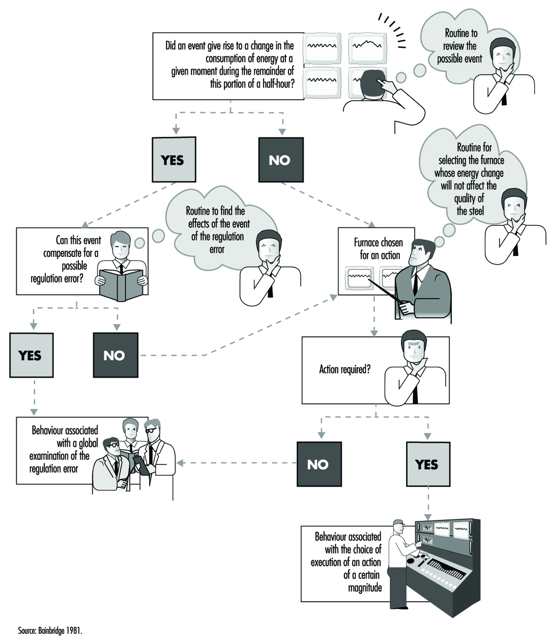
Since the arrival of the scientific organization of work, the concept of the prescribed task has been adversely criticized because it has been viewed as involving the imposition on workers of tasks that are not only designed without consulting their needs but are often accompanied by specific performance time, a restriction not welcomed by many workers. Even if the imposition aspect has become rather more flexible today and even if the workers contribute more often to the design of tasks, an assigned time for tasks remains necessary for schedule planning and remains an essential component of work organization. The quantification of time should not always be perceived in a negative manner. It constitutes a valuable indicator of workload. A simple but common method of measuring the time pressure exerted on a worker consists of determining the quotient of the time necessary for the execution of a task divided by the available time. The closer this quotient is to unity, the greater the pressure (Wickens 1992). Moreover, quantification can be used in flexible but appropriate personnel management. Let us take the case of nurses where the technique of predictive analysis of tasks has been generalized, for example, in the Canadian regulation Planning of Required Nursing (PRN 80) (Kepenne 1984) or one of its European variants. Thanks to such task lists, accompanied by their meantime of execution, one can, each morning, taking into account the number of patients and their medical conditions, establish a care schedule and a distribution of personnel. Far from being a constraint, PRN 80 has, in a number of hospitals, demonstrated that a shortage of nursing personnel exists, since the technique allows a difference to be established (see figure 4) between the desired and the observed, that is, between the number of staff necessary and the number available, and even between the tasks planned and the tasks carried out. The times calculated are only averages, and the fluctuations in the situation do not always make them applicable, but this negative aspect is minimized by a flexible organization that accepts adjustments and allows the personnel to participate in effecting those adjustments.
Figure 4. Discrepancies between the numbers of personnel present and required on the basis of PRN80
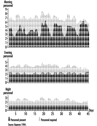
The activity, the evidence, and the performance
An activity is defined as the set of behaviors and resources used by the operator so that work occurs—that is to say, the transformation or production of goods or the rendering of a service. This activity can be understood through observation in different ways. Faverge (1972) has described four forms of analysis. The first is an analysis in terms of gestures and postures, where the observer locates, within the visible activity of the operator, classes of behavior that are recognizable and repeated during work. These activities are often coupled with a precise response: for example, the heart rate, which allows us to assess the physical load associated with each activity. The second form of analysis is in terms of information uptake. What is discovered, through direct observation—or with the aid of cameras or recorders of eye movements—is the set of signals picked up by the operator in the information field surrounding him or her. This analysis is particularly useful in cognitive ergonomics in trying to better understand the information processing carried out by the operator. The third type of analysis is in terms of regulation. The idea is to identify the adjustments of activity carried out by the operator in order to deal with either fluctuation in the environment or changes in his own condition. There we find the direct intervention of context within the analysis. One of the most frequently cited research projects in this area is that of Sperandio (1972). This author studied the activity of air traffic controllers and identified important strategy changes during an increase in air traffic. He interpreted them as an attempt to simplify the activity by aiming to maintain an acceptable load level, while at the same time continuing to meet the requirements of the task. The fourth is an analysis in terms of thought processes. This type of analysis has been widely used in the ergonomics of highly automated posts. Indeed, the design of computerized aids and notably intelligent aids for the operator requires a thorough understanding of the way in which the operator reasons in order to solve certain problems. The reasoning involved in scheduling, anticipation, and diagnosis has been the subject of analyses, an example of which can be found in figure 5. However, evidence of mental activity can only be inferred. Apart from certain observable aspects of behavior, such as eye movements and problem-solving time, most of these analyses resort to the verbal response. Particular emphasis has been placed, in recent years, on the knowledge necessary to accomplish certain activities, with researchers trying not to postulate them at the outset but to make them apparent through the analysis itself.
Figure 5. Analysis of mental activity. Strategies in the control of processes with long response times: the need for computerized support in diagnosis
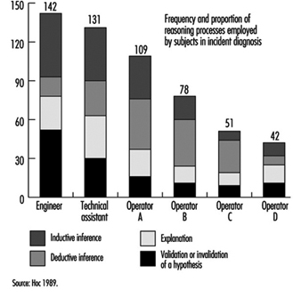
Such efforts have brought to light the fact that almost identical performances can be obtained with very different levels of knowledge, as long as operators are aware of their limits and apply strategies adapted to their capabilities. Hence, in our study of the start-up of a thermoelectric plant (De Keyser and Housiaux 1989), the start-ups were carried out by both engineers and operators. The theoretical and procedural knowledge that these two groups possessed, which had been elicited by means of interviews and questionnaires, were very different. The operators in particular sometimes had an erroneous understanding of the variables in the functional links of the process. In spite of this, the performances of the two groups were very close. But the operators took into account more variables in order to verify the control of the start-up and undertook more frequent verifications. Such results were also obtained by Amalberti (1991), who mentioned the existence of metaknowledge allowing experts to manage their own resources.
What evidence of activity is appropriate to elicit? Its nature, as we have seen, depends closely on the form of analysis planned. Its form varies according to the degree of methodological care exercised by the observer. Provoked evidence is distinguished from spontaneous evidence and concomitant from subsequent evidence. Generally speaking, when the nature of the work allows, concomitant and spontaneous evidence are to be preferred. They are free of various drawbacks such as the unreliability of memory, observer interference, the effect of rationalizing reconstruction on the part of the subject, and so forth. To illustrate these distinctions, we will take the example of verbalizations. Spontaneous verbalizations are verbal exchanges, or monologues expressed spontaneously without being requested by the observer; provoked verbalizations are those made at the specific request of the observer, such as the request made to the subject to “think aloud”, which is well known in the cognitive literature. Both types can be done in real-time, during work, and are thus concomitant.
They can also be subsequent, as in interviews, or subjects’ verbalizations when they view videotapes of their work. As for the validity of the verbalizations, the reader should not ignore the doubt raised in this regard by the controversy between Nisbett and De Camp Wilson (1977) and White (1988) and the precautions suggested by numerous authors aware of their importance in the study of mental activity in view of the methodological difficulties encountered (Ericson and Simon 1984; Savoyant and Leplat 1983; Caverni 1988; Bainbridge 1986).
The organization of this evidence, its processing and its formalization require descriptive languages and sometimes analyses that go beyond field observation. Those mental activities which are inferred from the evidence, for example, remain hypothetical. Today they are often described using languages derived from artificial intelligence, making use of representations in terms of schemes, production rules, and connecting networks. Moreover, the use of computerized simulations—of micro-worlds—to pinpoint certain mental activities has become widespread, even though the validity of the results obtained from such computerized simulations, in view of the complexity of the industrial world, is subject to debate. Finally, we must mention the cognitive modelings of certain mental activities extracted from the field. Among the best known is the diagnosis of the operator of a nuclear power plant, carried out in ISPRA (Decortis and Cacciabue 1990), and the planning of the combat pilot perfected in Centre d’études et de recherches de médecine aérospatiale (CERMA) (Amalberti et al. 1989).
Measurement of the discrepancies between the performance of these models and that of real, living operators is a fruitful field in activity analysis. Performance is the outcome of the activity, the final response given by the subject to the requirements of the task. It is expressed at the level of production: productivity, quality, error, incident, accident—and even, at a more global level, absenteeism or turnover. But it must also be identified at the individual level: the subjective expression of satisfaction, stress, fatigue or workload, and many physiological responses are also performance indicators. Only the entire set of data permits interpretation of the activity—that is to say, judging whether or not it furthers the desired goals while remaining within human limits. There exists a set of norms which, up to a certain point, guide the observer. But these norms are not situated—they do not take into account the context, its fluctuations and the condition of the worker. This is why in design ergonomics, even when rules, norms, and models exist, designers are advised to test the product using prototypes as early as possible and to evaluate the users’ activity and performance.
Individual or Collective Work?
While in the vast majority of cases, work is a collective act, most work analyses focus on tasks or individual activities. Nonetheless, the fact is that technological evolution, just like work organization, today emphasizes distributed work, whether it be between workers and machines or simply within a group. What paths have been explored by authors so as to take this distribution into account (Rasmussen, Pejtersen and Schmidts 1990)? They focus on three aspects: structure, the nature of exchanges and structural lability.
Structure
Whether we view structure as elements of the analysis of people, or of services, or even of different branches of a firm working in a network, the description of the links that unite them remains a problem. We are very familiar with the organigrams within firms that indicate the structure of authority and whose various forms reflect the organizational philosophy of the firm—very hierarchically organized for a Taylor-like structure, or flattened like a rake, even matrix-like, for a more flexible structure. Other descriptions of distributed activities are possible: an example is given in figure 6. More recently, the need for firms to represent their information exchanges at a global level has led to a rethinking of information systems. Thanks to certain descriptive languages—for example, design schemas, or entity-relations-attribute matrixes—the structure of relations at the collective level can today be described in a very abstract manner and can serve as a springboard for the creation of computerized management systems.
Figure 6. Integrated life cycle design
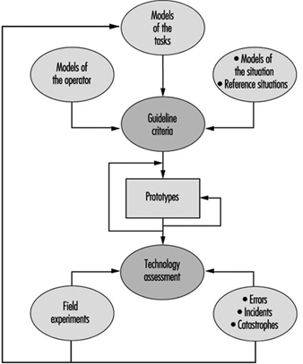
The nature of exchanges
Simply having a description of the links uniting the entities says little about the content itself of the exchanges; of course the nature of the relation can be specified—movement from place to place, information transfers, hierarchical dependence, and so on—but this is often quite inadequate. The analysis of communications within teams has become a favored means of capturing the very nature of collective work, encompassing subjects mentioned, creation of a common language in a team, modification of communications when circumstances are critical, and so forth (Tardieu, Nanci and Pascot 1985; Rolland 1986; Navarro 1990; Van Daele 1992; Lacoste 1983; Moray, Sanderson and Vincente 1989). Knowledge of these interactions is particularly useful for the creation of computer tools, notably decision-making aids for understanding errors. The different stages and the methodological difficulties linked to the use of this evidence have been well described by Falzon (1991).
Structural lability
It is the work on activities rather than on tasks that have opened up the field of structural lability—that is to say, of the constant reconfigurations of collective work under the influence of contextual factors. Studies such as those of Rogalski (1991), who over a long period analyzed the collective activities dealing with forest fires in France, and Bourdon and Weill Fassina (1994), who studied the organizational structure set up to deal with railway accidents, are both very informative. They clearly show how the context molds the structure of exchanges, the number, and type of actors involved, the nature of the communications and the number of parameters essential to the work. The more this context fluctuates, the further the fixed descriptions of the task are removed from reality. Knowledge of this lability, and a better understanding of the phenomena that take place within it, are essential in planning for the unpredictable and in order to provide better training for those involved in collective work in a crisis.
Conclusions
The various phases of the work analysis that have been described are an iterative part of any human factors design cycle (see figure 6). In this design of any technical object, whether a tool, a workstation or a factory, in which human factors are a consideration, certain information is needed in time. In general, the beginning of the design cycle is characterized by a need for data involving environmental constraints, the types of jobs that are to be carried out, and the various characteristics of the users. This initial information allows the specifications of the object to be drawn up so as to take into account work requirements. But this is, in some sense, only a coarse model compared to the real work situation. This explains why models and prototypes are necessary that, from their inception, allow not the jobs themselves, but the activities of the future users to be evaluated. Consequently, while the design of the images on a monitor in a control room can be based on a thorough cognitive analysis of the job to be done, only a data-based analysis of the activity will allow an accurate determination of whether the prototype will actually be of use in the actual work situation (Van Daele 1988). Once the finished technical object is put into operation, greater emphasis is put on the performance of the users and on dysfunctional situations, such as accidents or human error. The gathering of this type of information allows the final corrections to be made that will increase the reliability and usability of the completed object. Both the nuclear industry and the aeronautics industry serve as an example: operational feedback involves reporting every incident that occurs. In this way, the design loop comes full circle.
The Nature and Aims of Ergonomics
Definition and Scope
Ergonomics means literally the study or measurement of work. In this context, the term work signifies purposeful human function; it extends beyond the more restricted concept of work as labour for monetary gain to incorporate all activities whereby a rational human operator systematically pursues an objective. Thus it includes sports and other leisure activities, domestic work such as child care and home maintenance, education and training, health and social service, and either controlling engineered systems or adapting to them, for example, as a passenger in a vehicle.
The human operator, the focus of study, may be a skilled professional operating a complex machine in an artificial environment, a customer who has casually purchased a new piece of equipment for personal use, a child sitting in a classroom or a disabled person in a wheelchair. The human being is highly adaptable but not infinitely so. There are ranges of optimum conditions for any activity. One of the tasks of ergonomics is to define what these ranges are and to explore the undesirable effects which occur if the limits are transgressed—for example if a person is expected to work in conditions of excessive heat, noise or vibration, or if the physical or mental workload is too high or too low.
Ergonomics examines not only the passive ambient situation but also the unique advantages of the human operator and the contributions that can be made if a work situation is designed to permit and encourage the person to make the best use of his or her abilities. Human abilities may be characterized not only with reference to the generic human operator but also with respect to those more particular abilities that are called upon in specific situations where high performance is essential. For example, an automobile manufacturer will consider the range of physical size and strength of the population of drivers who are expected to use a particular model to ensure that the seats are comfortable, that the controls are readily identifiable and within reach, that there is clear visibility to the front and the rear, and that the internal instruments are easy to read. Ease of entry and egress will also be taken into account. By contrast, the designer of a racing car will assume that the driver is athletic so that ease of getting in and out, for example, is not important and, in fact, design features as a whole as they relate to the driver may well be tailored to the dimensions and preferences of a particular driver to ensure that he or she can exercise his or her full potential and skill as a driver.
In all situations, activities and tasks the focus is the person or persons involved. It is assumed that the structure, the engineering and any other technology is there to serve the operator, not the other way round.
History and Status
About a century ago it was recognized that working hours and conditions in some mines and factories were not tolerable in terms of safety and health, and the need was evident to pass laws to set permissible limits in these respects. The determination and statement of those limits can be regarded as the beginning of ergonomics. They were, incidentally, the beginning of all the activities which now find expression through the work of the International Labour Organization (ILO).
Research, development and application proceeded slowly until the Second World War. This triggered greatly accelerated development of machines and instrumentation such as vehicles, aircraft, tanks, guns and vastly improved sensing and navigation devices. As technology advanced, greater flexibility was available to allow adaptation to the operator, an adaptation that became the more necessary because human performance was limiting the performance of the system. If a powered vehicle can travel at a speed of only a few kilometres per hour there is no need to worry about the performance of the driver, but when the vehicle’s maximum speed is increased by a factor of ten or a hundred, then the driver has to react more quickly and there is no time to correct mistakes to avert disaster. Similarly, as technology is improved there is less need to worry about mechanical or electrical failure (for instance) and attention is freed to think about the needs of the driver.
Thus ergonomics, in the sense of adapting engineering technology to the needs of the operator, becomes simultaneously both more necessary and more feasible as engineering advances.
The term ergonomics came into use about 1950 when the priorities of developing industry were taking over from the priorities of the military. The development of research and application for the following thirty years is described in detail in Singleton (1982). The United Nations agencies, particularly the ILO and the World Health Organization (WHO), became active in this field in the 1960s.
In immediate postwar industry the overriding objective, shared by ergonomics, was greater productivity. This was a feasible objective for ergonomics because so much industrial productivity was determined directly by the physical effort of the workers involved—speed of assembly and rate of lifting and movement determined the extent of output. Gradually, mechanical power replaced human muscle power. More power, however, leads to more accidents on the simple principle that an accident is the consequence of power in the wrong place at the wrong time. When things are happening faster, the potential for accidents is further increased. Thus the concern of industry and the aim of ergonomics gradually shifted from productivity to safety. This occurred in the 1960s and early 1970s. About and after this time, much of manufacturing industry shifted from batch production to flow and process production. The role of the operator shifted correspondingly from direct participation to monitoring and inspection. This resulted in a lower frequency of accidents because the operator was more remote from the scene of action but sometimes in a greater severity of accidents because of the speed and power inherent in the process.
When output is determined by the speed at which machines function then productivity becomes a matter of keeping the system running: in other words, reliability is the objective. Thus the operator becomes a monitor, a trouble-shooter and a maintainer rather than a direct manipulator.
This historical sketch of the postwar changes in manufacturing industry might suggest that the ergonomist has regularly dropped one set of problems and taken up another set but this is not the case for several reasons. As explained earlier, the concerns of ergonomics are much wider than those of manufacturing industry. In addition to production ergonomics, there is product or design ergonomics, that is, adapting the machine or product to the user. In the car industry, for example, ergonomics is important not only to component manufacturing and the production lines but also to the eventual driver, passenger and maintainer. It is now routine in the marketing of cars and in their critical appraisal by others to review the quality of the ergonomics, considering ride, seat comfort, handling, noise and vibration levels, ease of use of controls, visibility inside and outside, and so on.
It was suggested above that human performance is usually optimized within a tolerance range of a relevant variable. Much of the early ergonomics attempted to reduce both muscle power output and the extent and variety of movement by way of ensuring that such tolerances were not exceeded. The greatest change in the work situation, the advent of computers, has created the opposite problem. Unless it is well designed ergonomically, a computer workspace can induce too fixed a posture, too little bodily movement and too much repetition of particular combinations of joint movements.
This brief historical review is intended to indicate that, although there has been continuous development of ergonomics, it has taken the form of adding more and more problems rather than changing the problems. However, the corpus of knowledge grows and becomes more reliable and valid, energy expenditure norms are not dependent on how or why the energy is expended, postural issues are the same in aircraft seats and in front of computer screens, much human activity now involves using videoscreens and there are well-established principles based on a mix of laboratory evidence and field studies.
Ergonomics and Related Disciplines
The development of a science-based application which is intermediate between the well-established technologies of engineering and medicine inevitably overlaps into many related disciplines. In terms of its scientific basis, much of ergonomic knowledge derives from the human sciences: anatomy, physiology and psychology. The physical sciences also make a contribution, for example, to solving problems of lighting, heating, noise and vibration.
Most of the European pioneers in ergonomics were workers among the human sciences and it is for this reason that ergonomics is well-balanced between physiology and psychology. A physiological orientation is required as a background to problems such as energy expenditure, posture and application of forces, including lifting. A psychological orientation is required to study problems such as information presentation and job satisfaction. There are of course many problems which require a mixed human sciences approach such as stress, fatigue and shift work.
Most of the American pioneers in this field were involved in either experimental psychology or engineering and it is for this reason that their typical occupational titles—human engineering and human factors—reflect a difference in emphasis (but not in core interests) from European ergonomics. This also explains why occupational hygiene, from its close relationship to medicine, particularly occupational medicine, is regarded in the United States as quite different from human factors or ergonomics. The difference in other parts of the world is less marked. Ergonomics concentrates on the human operator in action, occupational hygiene concentrates on the hazards to the human operator present in the ambient environment. Thus the central interest of the occupational hygienist is toxic hazards, which are outside the scope of the ergonomist. The occupational hygienist is concerned about effects on health, either long-term or short-term; the ergonomist is, of course, concerned about health but he or she is also concerned about other consequences, such as productivity, work design and workspace design. Safety and health are the generic issues which run through ergonomics, occupational hygiene, occupational health and occupational medicine. It is, therefore, not surprising to find that in a large institution of a research, design or production kind, these subjects are often grouped together. This makes possible an approach based on a team of experts in these separate subjects, each making a specialist contribution to the general problem of health, not only of the workers in the institution but also of those affected by its activities and products. By contrast, in institutions concerned with design or provision of services, the ergonomist might be closer to the engineers and other technologists.
It will be clear from this discussion that because ergonomics is interdisciplinary and still quite new there is an important problem of how it should best be fitted into an existing organization. It overlaps onto so many other fields because it is concerned with people and people are the basic and all-pervading resource of every organization. There are many ways in which it can be fitted in, depending on the history and objectives of the particular organization. The main criteria are that ergonomics objectives are understood and appreciated and that mechanisms for implementation of recommendations are built into the organization.
Aims of Ergonomics
It will be clear already that the benefits of ergonomics can appear in many different forms, in productivity and quality, in safety and health, in reliability, in job satisfaction and in personal development.
The reason for this breadth of scope is that its basic aim is efficiency in purposeful activity—efficiency in the widest sense of achieving the desired result without wasteful input, without error and without damage to the person involved or to others. It is not efficient to expend unnecessary energy or time because insufficient thought has been given to the design of the work, the workspace, the working environment and the working conditions. It is not efficient to achieve the desired result in spite of the situation design rather than with support from it.
The aim of ergonomics is to ensure that the working situation is in harmony with the activities of the worker. This aim is self-evidently valid but attaining it is far from easy for a variety of reasons. The human operator is flexible and adaptable and there is continuous learning, but there are quite large individual differences. Some differences, such as physical size and strength, are obvious, but others, such as cultural differences and differences in style and in level of skill, are less easy to identify.
In view of these complexities it might seem that the solution is to provide a flexible situation where the human operator can optimize a specifically appropriate way of doing things. Unfortunately such an approach is sometimes impracticable because the more efficient way is often not obvious, with the result that a worker can go on doing something the wrong way or in the wrong conditions for years.
Thus it is necessary to adopt a systematic approach: to start from a sound theory, to set measurable objectives and to check success against these objectives. The various possible objectives are considered below.
Safety and health
There can be no disagreement about the desirability of safety and health objectives. The difficulty stems from the fact that neither is directly measurable: their achievement is assessed by their absence rather than their presence. The data in question always pertain to departures from safety and health.
In the case of health, much of the evidence is long-term as it is based on populations rather than individuals. It is, therefore, necessary to maintain careful records over long periods and to adopt an epidemiological approach through which risk factors can be identified and measured. For example, what should be the maximum hours per day or per year required of a worker at a computer workstation? It depends on the design of the workstation, the kind of work and the kind of person (age, vision, abilities and so on). The effects on health can be diverse, from wrist problems to mental apathy, so it is necessary to carry out comprehensive studies covering quite large populations while simultaneously keeping track of differences within the populations.
Safety is more directly measurable in a negative sense in terms of kinds and frequencies of accidents and damage. There are problems in defining different kinds of accidents and identifying the often multiple causal factors and there is often a distant relationship between the kind of accident and the degree of harm, from none to fatality.
Nevertheless, an enormous body of evidence concerning safety and health has been accumulated over the past fifty years and consistencies have been discovered which can be related back to theory, to laws and standards and to principles operative in particular kinds of situations.
Productivity and efficiency
Productivity is usually defined in terms of output per unit of time, whereas efficiency incorporates other variables, particularly the ratio of output to input. Efficiency incorporates the cost of what is done in relation to achievement, and in human terms this requires the consideration of the penalties to the human operator.
In industrial situations, productivity is relatively easy to measure: the amount produced can be counted and the time taken to produce it is simple to record. Productivity data are often used in before/after comparisons of working methods, situations or conditions. It involves assumptions about equivalence of effort and other costs because it is based on the principle that the human operator will perform as well as is feasible in the circumstances. If the productivity is higher then the circumstances must be better. There is much to recommend this simple approach provided that it is used with due regard to the many possible complicating factors which can disguise what is really happening. The best safeguard is to try to make sure that nothing has changed between the before and after situations except the aspects being studied.
Efficiency is a more comprehensive but always a more difficult measure. It usually has to be specifically defined for a particular situation and in assessing the results of any studies the definition should be checked for its relevance and validity in terms of the conclusions being drawn. For example, is bicycling more efficient than walking? Bicycling is much more productive in terms of the distance that can be covered on a road in a given time, and it is more efficient in terms of energy expenditure per unit of distance or, for indoor exercise, because the apparatus required is cheaper and simpler. On the other hand, the purpose of the exercise might be energy expenditure for health reasons or to climb a mountain over difficult terrain; in these circumstances walking will be more efficient. Thus, an efficiency measure has meaning only in a well-defined context.
Reliability and quality
As explained above, reliability rather than productivity becomes the key measure in high technology systems (for instance, transport aircraft, oil refining and power generation). The controllers of such systems monitor performance and make their contribution to productivity and to safety by making tuning adjustments to ensure that the automatic machines stay on line and function within limits. All these systems are in their safest states either when they are quiescent or when they are functioning steadily within the designed performance envelope. They become more dangerous when moving or being moved between equilibrium states, for example, when an aircraft is taking off or a process system is being shut down. High reliability is the key characteristic not only for safety reasons but also because unplanned shut-down or stoppage is extremely expensive. Reliability is straightforward to measure after performance but is extremely difficult to predict except by reference to the past performance of similar systems. When or if something goes wrong human error is invariably a contributing cause, but it is not necessarily an error on the part of the controller: human errors can originate at the design stage and during setting up and maintenance. It is now accepted that such complex high-technology systems require a considerable and continuous ergonomics input from design to the assessment of any failures that occur.
Quality is related to reliability but is very difficult if not impossible to measure. Traditionally, in batch and flow production systems, quality has been checked by inspection after output, but the current established principle is to combine production and quality maintenance. Thus each operator has parallel responsibility as an inspector. This usually proves to be more effective, but it may mean abandoning work incentives based simply on rate of production. In ergonomic terms it makes sense to treat the operator as a responsible person rather than as a kind of robot programmed for repetitive performance.
Job satisfaction and personal development
From the principle that the worker or human operator should be recognized as a person and not a robot it follows that consideration should be given to responsibilities, attitudes, beliefs and values. This is not easy because there are many variables, mostly detectable but not quantifiable, and there are large individual and cultural differences. Nevertheless a great deal of effort now goes into the design and management of work with the aim of ensuring that the situation is as satisfactory as is reasonably practicable from the operator’s viewpoint. Some measurement is possible by using survey techniques and some principles are available based on such working features as autonomy and empowerment.
Even accepting that these efforts take time and cost money, there can still be considerable dividends from listening to the suggestions, opinions and attitudes of the people actually doing the work. Their approach may not be the same as that of the external work designer and not the same as the assumptions made by the work designer or manager. These differences of view are important and can provide a refreshing change in strategy on the part of everyone involved.
It is well established that the human being is a continuous learner or can be, given the appropriate conditions. The key condition is to provide feedback about past and present performance which can be used to improve future performance. Moreover, such feedback itself acts as an incentive to performance. Thus everyone gains, the performer and those responsible in a wider sense for the performance. It follows that there is much to be gained from performance improvement, including self-development. The principle that personal development should be an aspect of the application of ergonomics requires greater designer and manager skills but, if it can be applied successfully, can improve all the aspects of human performance discussed above.
Successful application of ergonomics often follows from doing no more than developing the appropriate attitude or point of view. The people involved are inevitably the central factor in any human effort and the systematic consideration of their advantages, limitations, needs and aspirations is inherently important.
Conclusion
Ergonomics is the systematic study of people at work with the objective of improving the work situation, the working conditions and the tasks performed. The emphasis is on acquiring relevant and reliable evidence on which to base recommendation for changes in specific situations and on developing more general theories, concepts, guidelines and procedures which will contribute to the continually developing expertise available from ergonomics.
Overview
In the 3rd edition of the ILO’s Encyclopaedia, published in 1983, ergonomics was summarized in one article that was only about four pages long. Since the publication of the 3rd edition, there has been a major change in emphasis and in understanding of interrelationships in safety and health: the world is no longer easily classifiable into medicine, safety and hazard prevention. In the last decade almost every branch in the production and service industries has expended great effort in improving productivity and quality. This restructuring process has yielded practical experience which clearly shows that productivity and quality are directly related to the design of working conditions. One direct economical measure of productivity—the costs of absenteeism through illness—is affected by working conditions. Therefore it should be possible to increase productivity and quality and to avoid absenteeism by paying more attention to the design of working conditions.
In sum, the simple hypothesis of modern ergonomics can be stated thus: Pain and exhaustion cause health hazards, wasted productivity and reduced quality, which are measures of the costs and benefits of human work.
This simple hypothesis can be contrasted to occupational medicine which generally restricts itself to establishing the aetiology of occupational diseases. Occupational medicine’s goal is to establish conditions under which the probability of developing such diseases is minimized. Using ergonomic principles these conditions can be most easily formulated in the form of demands and load limitations. Occupational medicine can be summed up as establishing “limitations through medico-scientific studies”. Traditional ergonomics regards its role as one of formulating the methods where, using design and work organization, the limitations established through occupational medicine can be put into practice. Traditional ergonomics could then be described as developing “corrections through scientific studies”, where “corrections” are understood to be all work design recommendations that call for attention to be paid to load limits only in order to prevent health hazards. It is a characteristic of such corrective recommendations that practitioners are finally left alone with the problem of applying them—there is no multidisciplinary team effort.
The original aim of inventing ergonomics in 1857 stands in contrast to this kind of “ergonomics by correction”:
... a scientific approach enabling us to reap, for the benefit of ourselves and others, the best fruits of life’s labour for the minimum effort and maximum satisfaction (Jastrzebowski 1857).
The root of the term “ergonomics” stems from the Greek “nomos” meaning rule, and “ergo” meaning work. One could propose that ergonomics should develop “rules” for a more forward-looking, prospective concept of design. In contrast to “corrective ergonomics”, the idea of prospective ergonomics is based on applying ergonomic recommendations which simultaneously take into consideration profitability margins (Laurig 1992).
The basic rules for the development of this approach can be deduced from practical experience and reinforced by the results of occupational hygiene and ergonomics research. In other words, prospective ergonomics means searching for alternatives in work design which prevent fatigue and exhaustion on the part of the working subject in order to promote human productivity (“... for the benefit of ourselves and others”). This comprehensive approach of prospective ergonomics includes workplace and equipment design as well as the design of working conditions determined by an increasing amount of information processing and a changing work organization. Prospective ergonomics is, therefore, an interdisciplinary approach of researchers and practitioners from a wide range of fields united by the same goal, and one part of a general basis for a modern understanding of occupational safety and health (UNESCO 1992).
Based on this understanding, the Ergonomics chapter in the 4th edition of the ILO Encyclopaedia covers the different clusters of knowledge and experiences oriented toward worker characteristics and capabilities, and aimed at an optimum use of the resource “human work” by making work more “ergonomic”, that is, more humane.
The choice of topics and the structure of articles in this chapter follows the structure of typical questions in the field as practised in industry. Beginning with the goals, principles and methods of ergonomics, the articles which follow cover fundamental principles from basic sciences, such as physiology and psychology. Based on this foundation, the next articles introduce major aspects of an ergonomic design of working conditions ranging from work organization to product design. “Designing for everyone” puts special emphasis on an ergonomic approach that is based on the characteristics and capabilities of the worker, a concept often overlooked in practice. The importance and diversity of ergonomics is shown in two examples at the end of the chapter and can also be found in the fact that many other chapters in this edition of the ILO Encyclopaedia are directly related to ergonomics, such as Heat and Cold, Noise, Vibration, Visual Display Units, and virtually all chapters in the sections Accident and Safety Management and Management and Policy.
General Profile
The complex merchant vessels, passenger ships and ships of war of the 1990s comprise tons of steel and aluminium as well as a variety of materials that range from the most common to the very exotic. Each vessel may contain hundreds or even thousands of kilometres of pipe and wire equipped with the most sophisticated power plants and electronic equipment available. They must be constructed and maintained to survive the most hostile of environments, while providing comfort and safety for the crews and passengers aboard and reliably completing their missions.
Ship construction and repair rank among the most hazardous industries in the world. According to the US Bureau of Labor Statistics (BLS), for example, shipbuilding and repair is one of the three most hazardous industries. While materials, construction methods, tools and equipment have changed, improved radically over time and continue to evolve, and while training and emphasis on safety and health have significantly improved the lot of the shipyard worker, the fact remains that throughout the world each year workers die or are seriously injured while employed in the construction, maintenance or repair of ships.
Despite advances in technology, many of the tasks and conditions associated with constructing, launching, maintaining and repairing today’s vessels are essentially the same as they were when the very first keel was laid thousands of years ago. The size and shape of the components of a vessel and the complexity of the work involved in assembling and outfitting them largely preclude any kind of automated processes, although some automation has been made possible by recent technological advances. Repair work remains largely resistant to automation. Work in the industry is very labour intensive, requiring highly specialized skills, which often must be utilized under less than ideal circumstances and in a physically challenging situation.
The natural environment in itself poses a significant challenge for shipyard work. While there are a few shipyards that have the capability to construct or repair vessels under cover, in most cases shipbuilding and repairing is done largely out of doors. There are shipyards located in every climatic region of the world, and while the more extreme northern yards are dealing with winter (i.e., slippery conditions wrought by ice and snow, short daylight hours and the physical effects on workers of long hours on cold steel surfaces, often in uncomfortable postures), the yards in more southerly climes are faced with the potential for heat stress, sunburn, working surfaces hot enough to cook on, insects and even snake bites. Much of this work is done over, in, under or around the water. Often, swift tidal currents may be whipped by the wind, causing a pitching and rolling working surface on which workers must perform very exacting tasks in a variety of positions, with tools and equipment that have the potential for inflicting serious physical injury. That same often unpredictable wind is a force to be reckoned with when moving, suspending or placing units often weighing in excess of 1,000 tons with a single or multiple crane lift. The challenges presented by the natural environment are manifold and provide for a seemingly endless combination of situations for which safety and health practitioners must design preventive measures. A well-informed and trained workforce is critical.
As the ship grows from the first steel plates which comprise the keel, it becomes an ever-changing, ever-more-complex environment with a constantly changing subset of potential hazards and hazardous situations requiring not only well-founded procedures for accomplishing the work, but mechanisms for recognizing and dealing with the thousands of unplanned situations which invariably arise during the construction process. As the vessel grows, scaffolding or staging is added continuously to provide access to the hull. While the very construction of this staging is highly specialized and at times inherently hazardous work, its completion means that workers are subjected to greater and greater risk as the height of the staging over the ground or water increases. As the hull begins to take form, the interior of the ship is also taking shape as modern construction methods permit large subassemblies to be stacked on one another, and enclosed and confined spaces are formed.
It is at this point in the process that the labour-intensive nature of the work is most apparent. Safety and health measures must be well coordinated. Worker awareness (for the safety of both the individual worker and those nearby) is fundamental to accident-free work.
Each space within the confines of the hull is designed for a very specialized purpose. The hull may be a void which will contain ballast, or it may house tanks, cargo holds, sleeping compartments or a highly sophisticated combat control centre. In every case building it will require a number of specialized workers to perform a variety of tasks within close proximity of one another. A typical scenario may find pipefitters brazing valves into position, electricians pulling wire cable and installing circuit boards, brush painters doing touch-up, shipfitters positioning and welding deckplates, crews of insulators or carpenters and a test crew verifying that a system is activated in the same area at the same time. Such situations, and others even more complex, take place all day, every day, in an ever-changing pattern dictated by schedule or engineering changes, personnel availability and even the weather.
The application of coatings presents a number of hazards. Spray-painting operations must be accomplished, often in confined spaces and with volatile paints and solvents and/or a variety of epoxy-type coatings, notorious for their sensitizing characteristics.
Enormous progress in the area of safety and health for the shipyard worker has been made over the years through the development of improved equipment and construction methods, safer facilities and a highly-trained workforce. However, the greatest gains have been made and continue to be made as we turn our attention toward the individual worker and focus on eliminating behaviour which contributes so significantly to accidents. While this could be said of almost any industry, the labour-intensive character of shipyard work makes it especially important. As we move toward safety and health programmes which more actively involve the worker and incorporate his or her ideas, not only does the worker’s awareness of the hazards inherent in the job and how to avoid them increase, he or she begins to feel ownership for the programme. It is with this ownership that true success in safety and health can be realized.
Automobile and Transportation Equipment History
General Profile
Distinct segments of the automobile and transportation equipment industry produce:
- cars and light trucks
- medium and heavy trucks
- buses
- farm and construction equipment
- industrial trucks
- motorcycles.
The characteristic assembly line for the finished vehicle is supported by separate manufacturing facilities for various parts and components. Vehicle components may be manufactured within the parent enterprise or purchased from separate corporate entities. The industry is a century old. Production in the North American, European and (since the Second World War) Japanese sectors of the industry became concentrated in a few corporations which maintained branch assembly operations in South America, Africa and Asia for sales to those markets. International trade in finished vehicles has increased since the 1970s, and trade in original equipment and replacement auto parts from facilities in the developing world is increasingly important.
Manufacture of heavy trucks, buses and farm and construction equipment are distinct businesses from car production, although some auto producers manufacture for both markets, and farm and construction equipment are also made by the same corporations. This line of products uses large diesel engines rather than gasoline engines. Production rates are typically slower, volumes smaller and processes less mechanized.
The types of facilities, the production processes and the typical components in car production are shown in table 1. Figure 1provides a flow chart for the steps in automobile production. The standard industrial classifications that are found in this industry include: motor vehicles and car body assembly, truck and bus body assembly, motor vehicle parts and accessories, iron and steel foundries, non-ferrous foundries, automotive stampings, iron and steel forgings, engine electrical equipment, auto and apparel trimmings and others. The number of people employed in the manufacture of parts exceeds that employed in assembly. These processes are supported by facilities for design of the vehicle, construction and maintenance of plant and equipment, clerical and managerial functions and a dealer and repair function. In the United States, car dealers, service stations and wholesale auto parts facilities employ about twice as many workers as the manufacturing functions.
Table 1. Production processes for automobile production.
|
Facility type |
Product and process |
|
Ferrous foundry |
Castings for machining into engine blocks and heads, other components |
|
Aluminium foundry and die cast |
Engine blocks and heads, transmission casings, other cast components |
|
Forging and heat treatment |
Pre-machined parts for engines, suspensions and transmissions |
|
Stamping |
Body panels and subassemblies |
|
Engine |
Machining of castings, assembly into finished product |
|
Transmission |
Machining of castings and forgings, assembly into product |
|
Glass |
Windshields, side windows and backlights |
|
Automotive parts |
Machining, stamping and assembly, including brakes, suspension parts, heating and air conditioning, pollution-control equipment, vehicle lighting |
|
Electrical and electronic |
Ignition systems, radios, motors, controllers |
|
Hardware and hard trim |
Polymer moulded exterior body panels, trim components |
|
Soft trim |
Seat cushions, built up seats, dashboard assemblies, interior body panels |
|
Vehicle assembly |
Body shop, painting, chassis assembly, final assembly |
|
Parts depots |
Warehousing, parts painting and assembly, packaging and shipping |
Figure 1. Flow chart for automobile production.
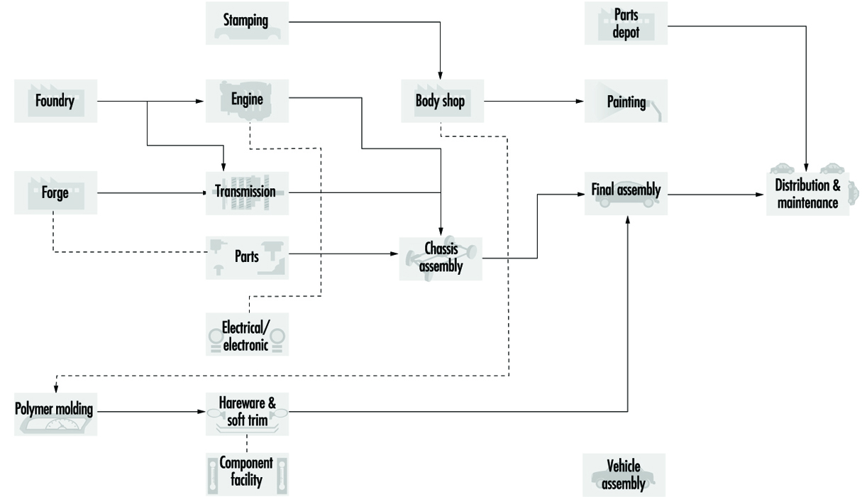
The workforce is predominantly male. In the United States, for example, it is about 80% male. Female employment is higher in trim and other lighter manufacturing processes. There is limited opportunity for job transfer from hourly work to clerical work or to technical and professional employment. Assembly line supervisors do, however, often come from the production and maintenance units. About 20% of hourly employees are employed in the skilled trades, although the fraction of employees in any particular facility who are in skilled trades varies greatly, from less than 10% in assembly operations to almost 50% in stamping operations. Because of contractions in employment levels over the decade of the 1980s, the average age of the workforce in the late 1990s exceeds 45 years, with hiring of new workers appearing only since 1994.
Major Sectors and Processes
Ferrous casting
Founding or metal casting involves the pouring of molten metal into a hollow inside a heat-resistant mould, which is the outside or negative shape of the pattern of the desired metal object. The mould may contain a core to determine the dimensions of any internal cavity in the final metal object. Foundry work consists of the following basic steps:
- making a pattern of the desired article from wood, metal, plastic or some other material
- making the mould by pouring sand and a binder around the pattern and compacting or setting it
- removing the pattern, inserting any core and assembling the mould
- melting and refining the metal in a furnace
- pouring the molten metal into the mould
- cooling the metal casting
- removing the mould and core from the metal casting by the “punch-out” process (for small castings) and by vibrating screens (shakeout) or hydro-blasting
- removing extra metal (e.g., the metal in the sprue—the pathway for molten metal to enter the mould) and burnt-on sand from the finished casting (fettling) by blasting with steel shot, hand chipping and grinding.
Ferrous foundries of the production type are a characteristic auto industry process. They are used in the automobile industry to produce engine blocks, heads and other parts. There are two basic types of ferrous foundries: gray iron foundries and ductile iron foundries. Gray iron foundries use scrap iron or pig iron (new ingots) to make standard iron castings. Ductile iron foundries add magnesium, cerium or other additives (often called ladle additives) to the ladles of molten metal before pouring to make nodular or malleable iron castings. The different additives have little impact on workplace exposures.
Typical automobile foundries use cupola or induction furnaces to melt the iron. A cupola furnace is a tall vertical furnace, open at the top, with hinged doors at the bottom. It is charged from the top with alternate layers of coke, limestone and metal; the molten metal is removed at the bottom. An induction furnace melts the metal by passing a high electric current through copper coils on the outside of the furnace. This induces an electric current in the outer edge of the metal charge, which heats the metal due to the high electrical resistance of the metal charge. Melting progresses from the outside of the charge to the inside.
In ferrous foundries, moulds are traditionally made from green sand (silica sand, coal dust, clay and organic binders), which is poured around the pattern, which is usually in two parts, and then compacted. This can be done manually or mechanically on a conveyor belt in production foundries. The pattern is then removed and the mould assembled mechanically or manually. The mould must have a sprue.
If the metal casting is to have a hollow interior, a core must be inserted into the mould. Cores can be made from thermosetting phenol-formaldehyde resins (or similar resins) mixed with sand which is then heated (hot box method) or from amine-cured urethane/sand mixtures which cure at room temperature (cold box method). The resin/sand mixture is poured into a core box which has a cavity in the desired shape of the core.
The products produced in gray iron castings are typically of a large size, such as engine blocks. The physical size increases the physical hazards on the job and also presents more difficult dust control problems.
Atmospheric contaminants in foundry processes
Silica-containing dusts. Silica-containing dusts are found in finishing, in shakeout-knockout, in moulding, in core making and in sand system and melt department maintenance activities. Air sampling studies during the 1970s typically found severalfold overexposures to silica, with the highest levels in finishing. Exposures were higher in mechanized production foundries than job shops. Improved control measures including enclosure and exhaust of sand systems and shakeout, mechanization and periodic industrial hygiene measurements have reduced levels. Standard ventilation designs are available for most foundry operations. Exposures above current limits persist in finishing operations due to inadequate sand removal after shakeout and silica burn-in on casting surfaces.
Carbon monoxide. Acutely dangerous carbon monoxide levels are encountered during cupola furnace maintenance and during upsets in process ventilation in the melt department. Excessive levels can also be encountered in cooling tunnels. Carbon monoxide exposures have also been associated with cupola melting and with the combustion of carbon material in green sand moulds. Exposure to sulphur dioxide of unknown origin can also occur, perhaps from sulphur contaminants in the mould.
Metal fumes. Metal fumes are found in melting and pouring operations. It is necessary to use compensating hoods over pouring stations in order to exhaust both metal fumes and combustion gases. Excessive exposures to lead fumes are occasionally encountered in iron foundries and are pervasive in brass foundries; lead fumes in gray iron arise from lead contamination of the scrap iron starting materials.
Other chemical and physical hazards. Formaldehyde, amine vapours and isocyanate pyrolysis products can be found in coremaking and core burn-off products. High-production coremaking is characteristic of the auto industry. Hot box phenol-formaldehyde coremaking replaced oil-sand cores in the mid-1960s and brought substantial formaldehyde exposures, which, in turn, increased the risks of respiratory irritation, lung function abnormalities and lung cancer. Protection requires local exhaust ventilation (LEV) at the core machine, core check stations and conveyor and low emission resins. When the phenol-formaldehyde coremaking has been replaced by cold box amine-cured polyurethane systems, effective maintenance of seals at the core box, and LEV where the cores are stored prior to insertion in the mould, are needed to protect employees against ocular effects of amine vapours.
Workers who are employed in these areas should undergo pre-placement and periodic medical examinations, including a chest x ray reviewed by an expert reader, a lung function test and a symptoms questionnaire, which are essential to detect early signs of pneumoconiosis, chronic bronchitis and emphysema. Periodic audiograms are needed, as hearing protection is often ineffective.
High levels of noise and vibration are encountered in processes such as furnace loading, mechanical de-coring, stripping and knockout of castings and fettling with pneumatic tools.
Foundry processes are heat intensive. The radiant heat load in melting, pouring, shakeout, core knockout and sprue removal requires special protective measures. Some of these measures include increased relief time (time away from the job), which is a common practice. Still extra relief during hot, summer months is also commonly provided. Workers should be outfitted with heat-protective clothing and eye and face protection in order to prevent the formation of cataracts. Climatized break areas near the work area improve the protective value of heat relief.
Aluminium casting
Aluminium casting (foundry and die-casting) is used to produce cylinder heads, transmission cases, engine blocks and other automotive parts. These facilities typically cast the products in permanent moulds, with and without sand cores, although the lost foam process has been introduced. In the lost foam process, the polystyrene foam pattern is not removed from the mould but is vaporized by the molten metal. Die casting involves the forcing of molten metal under pressure into metal moulds or dies. It is used to make large numbers of small, precise parts. Die-casting is followed by trim removal on a forge press and some finishing activities. Aluminium may be melted onsite or it can be delivered in molten form.
Hazards can arise because of significant pyrolysis of the core. Silica exposures may be found in permanent mould foundries where large cores are present. Local exhaust on shakeout is needed to prevent hazardous levels of exposure.
Other non-ferrous casting
Other non-ferrous die casting and electroplating processes are used to produce the trim on automotive products, the hardware and the bumpers. Electroplating is a process in which a metal is deposited onto another metal by an electrochemical process.
Bright metal trim traditionally was die-cast zinc, successively plated with copper, nickel and chrome, and then finished by polishing. Carburettor and fuel-injector parts are also die cast. Manual extraction of parts from die-casting machines is increasingly being replaced by mechanical extraction, and bright metal parts are being replaced by painted metal parts and plastic. Bumpers had been produced by pressing steel, followed by plating, but these methods are increasingly being replaced by the use of polymer parts in passenger vehicles.
Electroplating with chrome, nickel, cadmium, copper and so on is normally carried out in separate workshops and involves exposure to, inhalation of or contact with vapours from the acid plating baths. An increased incidence of cancer has been associated with both chromic acid and sulphuric acid mists. These mists are also extremely corrosive to the skin and respiratory tract. Electroplating baths should be labelled as to contents and should be fitted with special push-pull local exhaust systems. Anti-foaming surface tension agents should be added to the liquid in order to minimize mist formation. Workers should wear eye and face protection, hand and arm protection and aprons. Workers need periodic health checks as well.
Inserting and removing components from open-surface tanks are very hazardous operations which are increasingly becoming more mechanized. The buffing and polishing of plated components on felt belts or discs is strenuous and entails exposure to cotton, hemp and flax dust. This hazard can be minimized by providing a fixture or by mechanizing with transfer-type polishing machines.
Forging and heat treatment
Hot forging and cold forging followed by heat treatment are used to produce engine, transmission and suspension parts and other components.
Historically, automotive forging involved heating iron billets (bars) in individual oil-fired furnaces set close to individually operated steam hammer forges. In these drop hammer forges, the heated iron is placed in the bottom half of a metal die; the top half of the die is attached to the drop hammer. The iron is formed into the desired size and shape by multiple impacts of the dropping hammer. Today, such processes are replaced by induction heating of billets, which are worked in forging presses, which use pressure instead of impact to form the metal part, and drop hammer forges (upsetters) or by cold forging followed by heat treatment.
The forging process is extremely noisy. Noise exposure can be abated by replacing oil furnaces with induction heating devices, and the steam hammers with forging presses and upsetters. The process is also smoky. Oil smoke can be reduced by modernizing the furnace.
Forging and heat treatment are heat-intensive operations. Spot cooling using make-up air that circulates over workers in process areas is needed to reduce heat stress.
Machining
High production machining of engine blocks, crankshafts, transmissions and other components is characteristic of the auto industry. Machining processes are found within various parts manufacturing facilities and are the dominant process in engine, transmission and bearing production. Components such as camshafts, gears, differential pinions and brake drums are produced in machining operations. One-person machining stations are increasingly replaced by multiple station machines, machining cells and transfer lines which may be up to 200 metres in length. Soluble oils and synthetic and semi-synthetic coolants increasingly predominate over straight oils.
Foreign body injuries are common in machining operations; increased mechanical material handling and personal protective equipment are key preventive measures. Increased automation, particularly long transfer lines, increases the risk of severe acute trauma; improved machine guarding and energy lockout are preventive programmes.
The highest level of control measures for coolant mist include full enclosure of machining stations and fluid circulation systems, local exhaust directed outside or recirculated only through a high-efficiency filter, coolant system controls to reduce mist generation and coolant maintenance to control micro-organisms. Addition of nitrite to amine-containing fluids must be prohibited due to risk of nitrosamine production. Oils with substantial polynuclear aromatic hydrocarbon (PAH) content must not be used.
In case-hardening, tempering, nitrate salt baths and other metal heat-treatment processes using furnaces and controlled atmospheres, the microclimate may be oppressive and various airborne toxic substances encountered (e.g., carbon monoxide, carbon dioxide, cyanides).
Machine attendants and workers handling swarf and centrifuging cutting oil prior to filtration and regeneration are exposed to the risk of dermatitis. Exposed workers should be provided with oil-resistant aprons and encouraged to wash thoroughly at the end of each shift.
Grinding and tool sharpening may present a danger of hard metal disease (interstitial lung disease) unless cobalt exposure is measured and controlled. Grinding wheels should be fitted with screens, and eye and face protection and respiratory protective equipment should be worn by grinders.
Machined parts are typically assembled into a finished component, with attendant ergonomic risks. In engine facilities engine testing and running-in must be carried out at test stations fitted with equipment for removing exhaust gases (carbon monoxide, carbon dioxide, unburned hydrocarbons, aldehydes, nitrogen oxides) and with noise-control facilities (booths with sound-absorbent walls, insulated bedplates). Noise levels may be as high as 100 to 105 dB with peaks at 600 to 800 Hz.
Stamping
Pressing of sheet metal (steel) into body panels and other components, often combined with subassembly by welding, is done in large facilities with large and small mechanical power presses. Individual load and unload presses were successively replaced by mechanical extraction devices and now shuttle transfer mechanisms which can load as well, yielding fully automated press lines. Fabrication of subassemblies such as hoods and doors is accomplished with resistance welding presses and is increasingly performed in cells with robot transfer of parts.
The main process is the pressing of steel sheet, strip and light sections on mechanical power presses ranging in capacity from roughly 20 to 2,000 tonnes.
Modern press safety requires effective machinery guarding, prohibition of hands in dies, safety controls including anti-tie down two-hand controls, part revolution clutches and brake monitors, automatic feed and ejection systems, collection of press scrap and the use of personal protective equipment such as aprons, foot and leg protection and hand and arm protection. Outmoded and hazardous full-revolution clutch machines and pull-back devices must be eliminated. Handling rolled steel with cranes and loading of decoilers prior to blanking at the head of a press lines poses a severe safety hazard.
Press operators are exposed to substantial mist levels from drawing compounds which are similar in composition to machining fluids such as soluble oils. Welding fumes are present in fabrication. Noise exposures are high in stamping. Control measures for noise include mufflers on air valves, lining metal chutes with vibration-damping equipment, quieting parts carts, and isolation of presses; the point of operation of the press is not the main site of noise generation.
Following pressing, the pieces are assembled into sub-groups such as hoods and doors using resistance welding presses. Chemical hazards include welding fumes from primarily resistance welding and pyrolysis products of surface coatings, including drawing compound and sealers.
Plastic body panels and trim components
Metal trim parts such as chrome strips are being increasingly replaced by polymer materials. Hard body parts may be made from fibrous glass-reinforced polyester polystyrene systems, acrylonitrile-butadiene-styrene (ABS) thermosetting systems or polyethylene. Polyurethane systems may be high density for body parts, such as nose cones, or low-density foam for seats and interior padding.
Polyurethane foam moulding presents severe respiratory sensitization problems from inhalation of di-isocyanate monomer and possibly catalysts. Complaints persist in operations which are in compliance with limits for toluene di-isocyanate (TDI). Methylene chloride exposures from gun flushing can be substantial. Pouring stations need enclosure and LEV; spills of isocyanate should be minimized by safety devices and cleaned promptly by trained crews. Fires in curing ovens are also a problem in these facilities. Seat manufacture has severe ergonomic stresses, which can be reduced by fixtures, especially for stretching upholstery over cushions.
Styrene exposure from fibrous glass lay-up should be controlled by enclosing storage of mats and local exhaust. Dusts from grinding cured parts contain fibrous glass and should also be controlled by ventilation.
Vehicle assembly
Assembly of components into the finished vehicle typically takes place on a mechanized conveyor involving upwards of a thousand employees per shift, with additional support personnel. The largest segment of employees in the industry are in this process type.
A vehicle assembly plant is divided into distinct units: the body shop, which can include subassembly activities also found in a stamping; paint; chassis assembly; cushion room (which can be outsourced); and final assembly. Paint processes have evolved toward lower-solvent, more reactive formulations in recent years, with increasing use of robot and mechanical application. The body shop has become increasingly automated with reduced arc welding and replacement of hand-operated spot-welding guns with robots.
Light truck assembly (vans, pickups, sport utility vehicles) is similar in process to car assembly. Heavy truck, farm and construction equipment manufacture involves less mechanization and automation, longer cycle jobs, heavier physical labour, more arc welding and different paint systems.
The body shop of an assembly plant assembles the shell of the vehicle. Resistance welding machines may be transfer type, robotic or individually operated. Suspended spot welding machines are heavy and cumbersome to manipulate even when fitted with a counterbalance system. Transfer machines and robots have eliminated many manual jobs and removed workers from close, direct exposure to hot metal, sparks and combustion products of the mineral oil which contaminates the sheet metal. However, increased automation carries increased risk of severe injury to maintenance workers; energy lockout programmes and more elaborate and automatic machine guarding systems, including presence-sensing devices, are needed in automated body shops. Arc welding is employed to a limited degree. During this work, employees are exposed to intense visible and ultraviolet radiation and risk inhalation of combustion gases. LEV, protective screens and partitions, welding visors or goggles, gloves and aprons are needed for arc welders.
The body shop has the greatest laceration and foreign body injury hazards.
In past years assembly techniques and body panel defect retouching processes entailed soldering with lead and tin alloys (also containing traces of antimony). Soldering and especially the grinding away of excess solder produced a severe risk of lead poisoning, including fatal cases when the process was introduced in the 1930s. Protective measures included an isolated solder grind booth, respirators supplying positive-pressure air for solder grinders, hygiene facilities and lead-in-blood monitoring. Nevertheless, increased body burdens of lead and occasional cases of lead poisoning among workers and families persisted into the 1970s. Lead body solder has been eliminated in US passenger vehicles. In addition, noise levels in these processes may range up to 95 to 98 dB, with peaks at 600 to 800 Hz.
Automobile bodies from the body shop enter the paint shop on a conveyor where they are degreased, often by the manual application of solvents, cleaned in a closed tunnel (bonderite) and undercoated. The undercoat is then rubbed down by hand with an oscillating tool using wet abrasive paper, and the final layers of paint are applied and then cured in an oven. In paint shops, workers may inhale toluene, xylene, methylene chloride, mineral spirits, naphtha, butyl and amyl acetate and methyl alcohol vapours from body, booth and paint gun cleaning. Spray painting is carried on in downdraft booths with a continuously filtered air supply. Solvent vapour at painting stations is typically well controlled by down-draft ventilation, which is needed for product quality. Inhalation of paint particulate was formerly less well controlled, and some paints in the past contained salts of chromium and lead. In a well controlled booth, the workers should not have to wear respiratory protective equipment to achieve compliance with exposure limits. Many voluntarily wear respirators for overspray. Recently introduced two-component polyurethane paints should be sprayed only when air-supplied helmets are used with suitable booth re-entry times. Environmental regulations have spurred the development of high-solids paints with lower solvent content. Newer resin systems may generate substantial formaldehyde exposure, and powdered paints now being introduced are epoxy formulations which may be sensitizers. Recirculation of paint booth and oven exhaust from roof ventilating units into work areas outside the booth is a common complaint; this problem can be prevented by exhaust stacks of sufficient height.
In the production of commercial vehicles (lorries (trucks), trams, trolley buses) and farm and construction equipment, manual spray painting is still widely employed due to the large surfaces to be covered and the need for frequent retouching. Lead and chromate paints may still be employed in these operations.
The painted body work is dried in hot air and infra-red ovens fitted with exhaust ventilation and then moves on to join the mechanical components in the final assembly shop, where the body, engine and transmission are joined together and the upholstery and internal trim are fitted. It is here that conveyor belt work is to be seen in its most highly developed version. Each worker carries out a series of tasks on each vehicle with cycle times of about 1 minute. The conveyor system transports the bodies gradually along the assembly line. These processes demand constant vigilance and may be highly monotonous and act as stressors on certain subjects. Although normally not imposing excessive metabolic lead, these processes virtually all involve moderate to severe risk factors for musculoskeletal disorders.
The postures or movements the worker is obliged to adopt, such as when installing components inside the vehicle or working under the body (with hands and forearms above head level) are the most readily abated hazards, although force and repetition must also be reduced to abate risk factors. After final assembly the vehicle is tested, finished and dispatched. Inspection can be limited to roller tests on a roller bed (where ventilation of exhaust fumes is important) or can include track trials on different types of surface, water and dust tightness trials and road trials outside the factory.
Parts depots
Parts depots are integral to distributing the finished product and supplying repair parts. Workers in these high-production warehouses use order pickers to retrieve parts from elevated locations, with automated parts-delivery systems in three-shift operations. Manual handling of packaged parts is common. Painting and other production processes may be found in parts depots.
Testing of prototypes
Testing of automobile prototypes is specialized to the industry. Test drivers are exposed to a variety of physiological stresses, such as violent acceleration and deceleration, jolting and vibration, carbon monoxide and exhaust fumes, noise, work spells of prolonged duration and different ambient and climatic conditions. Endurance drivers endure special stresses. Fatal vehicle accidents occur in this occupation.
Assembly of heavy trucks and farm and construction equipment
The processes in these industry sectors are essentially the same as in the assembly of cars and light trucks. Contrasts include: slower pace of production, including non-assembly-line operations; more arc welding; riveting of truck cabs; movement of components by crane; use of chromate-containing pigments; and diesel on drive-off at the end of the assembly line. These sectors include more producers relative to volume and are less vertically integrated.
Manufacture of locomotives and rail cars
Distinct segments of railroad equipment manufacture include locomotives, passenger cars, freight cars and electric self-propelled passenger cars. Compared to car and truck manufacture, assembly processes involve longer cycles; there is more reliance on cranes for material handling; and arc welding is more heavily used. The large size of the products makes engineering control of spray paint operations difficult and creates situations where workers are completely enclosed in the product while welding and spray painting.
Health Problems and Disease Patterns
Production processes are not unique to the auto industry, but often the scale of production and the high degree of integration and automation combine to present special hazards to employees. Hazards to employees in this complex industry must be arrayed in three dimensions: process type, job classification group and adverse outcome.
Adverse outcomes with distinct cause and prevention methods can be distinguished as: fatal and severe acute injuries; injuries generally; repeated trauma disorders; short-onset chemical effects; occupational disease from long-term chemical exposure; service sector hazards (including infectious disease and client- or customer-initiated violence); and work environment hazards such as psychosocial stress.
Job classification groups in the automobile industry can usefully be divided by divergent hazard spectra: skilled trades (maintenance, service, fabrication and installation of production equipment); mechanical material handling (powered industrial truck and crane operators); production service (including non-skilled maintenance and cleaners); fixed production (the largest grouping, including assemblers and machine operators); clerical and technical; and executive and managerial.
Health and safety outcomes common to all processes
According to the US Bureau of Labor Statistics, the auto industry has one of the highest injury rates overall, with 1 in 3 employees hurt each year, 1 in 10 seriously enough to lose time from work. Lifetime risk of occupational fatality from acute traumatic injury is 1 in 2,000. Certain hazards are generally characteristic of occupational groupings throughout the industry. Other hazards, particularly chemicals, are characteristic of specific production processes.
Skilled trades and mechanical material-handling occupations are at high risk for fatal and severe acute traumatic injuries. The skilled trades are less than 20% of the workforce, yet suffer 46% of fatal occupational injuries. Mechanical material-handling occupations suffer 18% of fatalities. The skilled-trades fatalities largely occur during maintenance and service activities, with uncontrolled energy as the leading cause. Preventive measures include energy lockout programmes, machine guarding, fall prevention and industrial truck and crane safety, all based on directed job safety analysis.
By contrast, fixed production occupations suffer higher rates of injuries generally and repeated trauma disorders, but are at reduced risk to fatal injury. Musculoskeletal injuries, including repeated trauma disorders and closely related strains and sprains caused by overexertion or repetitive motion are 63% of disabling injuries in assembly facilities and about half the injuries in other process types. The chief preventive measures are ergonomics programmes based on risk factor analysis and structured reduction in force, frequency and postural stresses of high-risk jobs.
Production service occupations and skilled trades face the majority of acute and high-level chemical hazards. Typically these exposures occur during routine cleaning, response to spills and process upsets and in confined space entry during maintenance and service activities. Solvent exposures are prominent among these hazardous situations. The long-term health consequences of these intermittent high exposures are not known. High exposures to carcinogenic coal tar pitch volatiles are experienced by employees tarring wood block floors in many facilities or torching floor bolts in stamping plants. Excess mortality from lung cancer has been observed in such groups. Preventive measures focus on confined space entry and hazardous waste and emergency response programmes, although long-term prevention depends on process change to eliminate exposure.
Effects of chronic exposure to chemicals and some physical agents are most evident among fixed production workers, principally because these groups can more feasibly be studied. Virtually all the process-specific adverse effects described above arise from exposures in compliance with existing occupational exposure limits, so protection will depend on reduction of allowable limits. In the near term, best practices including well designed and maintained exhaust systems serve to reduce exposures and risks.
Noise-induced hearing loss is pervasive in all segments of the industry.
All sectors of the workforce are subject to psychosocial stress, although these are more apparent in the clerical, technical, administrative support, managerial and professional occupations because of their generally less intense exposure to other hazards. Nevertheless, job stress is likely more intense among production and maintenance employees, and stress effects are likely greater. No effective means of reducing stresses from night work and rotating shift work have been implemented, although shift preference agreements allow for some self selection, and shift premiums compensate those employees assigned to off shifts. Acceptance of rotating shifts by the workforce is historical and cultural. Skilled trades and maintenance employees work substantially more overtime and during holidays, vacations and shutdowns, compared to production employees. Typical work schedules include two production shifts and a shorter maintenance shift; this provides flexibility for overtime in periods of increased production.
The discussion which follows groups chemical and some specific physical hazards by production type and addresses injury and ergonomic hazards by job classification.
Foundries
Foundries stand out among auto industry processes with a higher fatality rate, arising from molten metal spills and explosions, cupola maintenance, including bottom drop, and carbon monoxide hazards during relining. Foundries report a higher fraction of foreign body, contusion and burn injuries and a lower fraction of musculoskeletal disorders than other facilities. Foundries also have the highest noise exposure levels (Andjelkovich et al. 1990; Andjelkovich et al. 1995; Koskela 1994; Koskela et al. 1976; Silverstein et al. 1986; Virtamo and Tossavainen 1976).
A recent review of mortality studies including the American auto industry showed that foundry workers experienced increased rates of deaths from lung cancer in 14 of 15 studies (Egan-Baum, Miller and Waxweiller 1981; Mirer et al. 1985). Because high lung cancer rates are found among cleaning room workers where the primary exposure is silica, it is likely that mixed silica-containing dust exposure is a major cause (IARC 1987, 1996), although polynuclear aromatic hydrocarbon exposures are also found. Increased mortality from non-malignant respiratory disease was found in 8 of 11 studies. Silicosis deaths were recorded as well. Clinical studies find x-ray changes characteristic of pneumoconiosis, lung function deficits characteristic of obstruction and increased respiratory symptoms in modern production foundries with the highest levels of controls. These effects arose from exposure conditions which prevailed from the 1960s onward and strongly indicate that health risks persist under current conditions as well.
Asbestos effects are found on x ray among foundry workers; victims include production as well as maintenance workers with identifiable asbestos exposures.
Machining operations
A recent review of mortality studies among workers in machining operations found apparent exposure-related increased stomach, oesophageal, rectal, pancreatic and laryngeal cancer in multiple studies (Silverstein et al. 1988; Eisen et al. 1992). Known carcinogenic agents historically present in coolants include polynuclear aromatic compounds, nitrosamines, chlorinated paraffins and formaldehyde. Present formulations contain reduced amounts of these agents, and exposures to coolant particulate are reduced, but cancer risk may still occur with present exposures. Clinical studies have documented occupational asthma, increased respiratory symptoms, cross-shift lung function drop and, in one case, legionnaire’s disease associated with coolant mist exposure (DeCoufle 1978; Vena et al. 1985; Mallin, Berkeley and Young 1986; Park et al. 1988; Delzell et al. 1993). Respiratory effects are more prominent with synthetics and soluble oils, which contain chemical irritants such as petroleum sulphonates, tall oils, ethanolamines, formaldehyde and formaldehyde donor biocides, as well as bacterial products such as endotoxin. Skin disorders are still common among machining workers, with greater problems reported for those exposed to synthetic fluids.
Pressed metal operations
The characteristic injury hazards in mechanical power presswork are crushing and amputation injuries, especially of the hands, due to trapping in the press, and hand, foot and leg injuries, caused by scrap metal from the press.
Pressed metal facilities have twice the proportion of laceration injuries of auto industry facilities generally. Such operations have a higher proportion of skilled workers than typical for the industry, especially if die construction is pursued onsite. Die change is an especially hazardous activity.
Mortality studies in the metal-stamping industry are limited. One such study found increased mortality from stomach cancer; another found increased mortality from lung cancer among maintenance welders and millwrights exposed to coal tar pitch volatiles.
Hardware and electroplating
A mortality study of employees at an automotive hardware plant found excess mortality from lung cancer among workers in departments which integrated zinc die-cast and electroplating. Chromic and sulphuric acid mist or die-cast smoke were likely causes.
Vehicle assembly
Injury rates, including cumulative trauma disorders (CTDs), are now the highest in assembly of all processes in the auto sector, due largely to the high rate of musculoskeletal disorders from repetitive work or overexertion. Musculoskeletal disorders account for more than 60% of disabling injuries in this sector.
Several mortality studies in assembly plants observed increased deaths from lung cancer. No specific process within the assembly sector has been shown responsible, so this issue remains under investigation.
Testing of prototypes
Fatal vehicle accidents occur in this occupation.
Design work
The design staffs of auto companies have been the subject of health and safety concern. Prototype dies are made by first constructing the pattern of wood, using extremely hard wood, laminates and particleboard. Plastic models are made by fibrous glass lay-up with polyester-polystyrene resins. Metal models are essentially dies constructed by precision machining. Wood, plastic and metal model and pattern makers have been shown to suffer excess incidence and mortality from colon and rectal cancer in repeated studies. A specific agent has not been identified.
Environmental and Public Health Issues
Environmental regulation aimed at stationary sources in the auto industry principally addresses volatile organic compounds from spray painting and other surface coatings. Pressure to reduce solvent content of paints has actually changed the nature of the coatings used. These rules affect supplier and parts plants as well as vehicle assembly. Foundries are regulated for air emissions of particulates and sulphur dioxide, while spent sand is treated as hazardous waste.
Vehicle emissions and vehicle safety are critical public health and safety issues regulated outside the occupational arena.
More...
Asbestos: Historical Perspective
Several examples of workplace hazards often are quoted to exemplify not only the possible adverse health effects associated with workplace exposures, but also to reveal how a systematic approach to the study of worker populations can uncover important exposure-disease relationships. One such example is that of asbestos. The simple elegance with which the late Dr. Irving J. Selikoff demonstrated the elevated cancer risk among asbestos workers has been documented in an article by Lawrence Garfinkel. It is reprinted here with only slight modification and with the permission of CA-A Cancer Journal for Clinicians (Garfinkel 1984). The tables came from the original article by Dr. Selikoff and co-workers (1964).
Asbestos exposure has become a public health problem of considerable magnitude, with ramifications that extend beyond the immediate field of health professionals to areas served by legislators, judges, lawyers, educators, and other concerned community leaders. As a result, asbestos-related diseases are of increasing concern to clinicians and health authorities, as well as to consumers and the public at large.
Historical Background
Asbestos is a highly useful mineral that has been utilized in diverse ways for many centuries. Archaeological studies in Finland have shown evidence of asbestos fibres incorporated in pottery as far back as 2500 BC. In the 5th century BC, it was used as a wick for lamps. Herodotus commented on the use of asbestos cloth for cremation about 456 BC. Asbestos was used in body armour in the 15th century, and in the manufacture of textiles, gloves, socksand handbags in Russia c. 1720. Although it is uncertain when the art of weaving asbestos was developed, we know that the ancients often wove asbestos with linen. Commercial asbestos production began in Italy about 1850, in the making of paper and cloth.
The development of asbestos mining in Canada and South Africa about 1880 reduced costs and spurred the manufacture of asbestos products. Mining and production of asbestos in the United States, Italy and Russia followed soon after. In the United States, the development of asbestos as pipe insulation increased production and was followed shortly thereafter by other varied uses including brake linings, cement pipes, protective clothing and so forth.
Production in the US increased from about 6,000 tons in 1900 to 650,000 tons in 1975, although by 1982, it was about 300,000 tons and by 1994, production had dropped to 33,000 tons.
It is reported that Pliny the Younger (61-113 AD) commented on the sickness of slaves who worked with asbestos. Reference to occupational disease associated with mining appeared in the 16th century, but it was not until 1906 in England that the first reference to pulmonary fibrosis in an asbestos worker appeared. Excess deaths in workers involved with asbestos manufacturing applications were reported shortly thereafter in France and Italy, but major recognition of asbestos-induced disease began in England in 1924. By 1930, Wood and Gloyne had reported on 37 cases of pulmonary fibrosis.
The first reference to carcinoma of the lung in a patient with “asbestos-silicosis” appeared in 1935. Several other case reports followed. Reports of high percentages of lung cancer in patients who died of asbestosis appeared in 1947, 1949 and 1951. In 1955 Richard Doll in England reported an excess risk of lung cancer in persons who had worked in an asbestos plant since 1935, with an especially high risk in those who were employed more than 20 years.
Clinical Observations
It was against this background that Dr. Irving Selikoff’s clinical observations of asbestos-related disease began. Dr. Selikoff was at that time already a distinguished scientist. His prior accomplishments included the development and first use of isoniazid in the treatment of tuberculosis, for which he received a Lasker Award in 1952.
In the early 1960s, as a chest physician practising in Paterson, New Jersey, he had observed many cases of lung cancer among workers in an asbestos factory in the area. He decided to extend his observations to include two locals of the asbestos insulator workers union, whose members also had been exposed to asbestos fibres. He recognized that there were still many people who did not believe that lung cancer was related to asbestos exposure and that only a thorough study of a total exposed population could convince them. There was the possibility that asbestos exposure in the population could be related to other types of cancer, such as pleural and peritoneal mesothelioma, as had been suggested in some studies, and perhaps other sites as well. Most of the studies of the health effects of asbestos in the past had been concerned with workers exposed in the mining and production of asbestos. It was important to know if asbestos inhalation also affected other asbestos-exposed groups.
Dr. Selikoff had heard of the accomplishments of Dr. E. Cuyler Hammond, then Director of the Statistical Research Section of the American Cancer Society (ACS), and decided to ask him to collaborate in the design and analysis of a study. It was Dr. Hammond who had written the landmark prospective study on smoking and health published a few years earlier.
Dr. Hammond immediately saw the potential importance of a study of asbestos workers. Although he was busily engaged in analysing data from the then new ACS prospective study, Cancer Prevention Study I (CPS I), which he had begun a few years earlier, he readily agreed to a collaboration in his “spare time”. He suggested confining the analysis to those workers with at least 20 years’ work experience, who thus would have had the greatest amount of asbestos exposure.
The team was joined by Mrs. Janet Kaffenburgh, a research associate of Dr. Selikoff’s at Mount Sinai Hospital, who worked with Dr. Hammond in preparing the lists of the men in the study, including their ages and dates of employment and obtaining the data on facts of death and causes from union headquarters records. This information was subsequently transferred to file cards that were sorted literally on the living room floor of Dr. Hammond’s house by Dr. Hammond and Mrs. Kaffenburgh.
Dr. Jacob Churg, a pathologist at Barnert Memorial Hospital Center in Paterson, New Jersey, provided pathologic verification of the cause of death.
Tabe 1. Man-years of experience of 632 asbestos workers exposed to asbestos dust 20 years or longer
|
Age |
Time period |
|||
|
1943-47 |
1948-52 |
1953-57 |
1958-62 |
|
|
35–39 |
85.0 |
185.0 |
7.0 |
11.0 |
|
40–44 |
230.5 |
486.5 |
291.5 |
70.0 |
|
45–49 |
339.5 |
324.0 |
530.0 |
314.5 |
|
50–54 |
391.5 |
364.0 |
308.0 |
502.5 |
|
55–59 |
382.0 |
390.0 |
316.0 |
268.5 |
|
60–64 |
221.0 |
341.5 |
344.0 |
255.0 |
|
65–69 |
139.0 |
181.0 |
286.0 |
280.0 |
|
70–74 |
83.0 |
115.5 |
137.0 |
197.5 |
|
75–79 |
31.5 |
70.0 |
70.5 |
75.0 |
|
80–84 |
5.5 |
18.5 |
38.5 |
23.5 |
|
85+ |
3.5 |
2.0 |
8.0 |
13.5 |
|
Total |
1,912.0 |
2,478.0 |
2,336.5 |
2,011.0 |
The resulting study was of the type classified as a “prospective study retrospectively carried out”. The nature of the union records made it possible to accomplish an analysis of a long-range study in a relatively short period of time. Although only 632 men were involved in the study, there were 8,737 man-years of exposure to risk (see table 1); 255 deaths occurred during the 20-year period of observation from 1943 through 1962 (see table 2). It is in table 28.17 where the observed number of deaths can be seen invariably to exceed the number expected, demonstrating the association between workplace asbestos exposure and an elevated cancer death rate.
Table 2. Observed and expected number of deaths among 632 asbestos workers exposed to asbestos dust 20 years or longer
|
Cause of death |
Time period |
Total |
|||
|
1943-47 |
1948-52 |
1953-57 |
1958-62 |
1943-62 |
|
|
Total, all causes |
|||||
|
Observed (asbestos workers) |
28.0 |
54.0 |
85.0 |
88.0 |
255.0 |
|
Expected (US White males) |
39.7 |
50.8 |
56.6 |
54.4 |
203.5 |
|
Total cancer, all sites |
|||||
|
Observed (asbestos workers) |
13.0 |
17.0 |
26.0 |
39.0 |
95.0 |
|
Expected (US White males) |
5.7 |
8.1 |
13.0 |
9.7 |
36.5 |
|
Cancer of lung and pleura |
|||||
|
Observed (asbestos workers) |
6.0 |
8.0 |
13.0 |
18.0 |
45.0 |
|
Expected (US White males) |
0.8 |
1.4 |
2.0 |
2.4 |
6.6 |
|
Cancer of stomach, colon and rectum |
|||||
|
Observed (asbestos workers) |
4.0 |
4.0 |
7.0 |
14.0 |
29.0 |
|
Expected (US White males) |
2.0 |
2.5 |
2.6 |
2.3 |
9.4 |
|
Cancer of all other sites combined |
|||||
|
Observed (asbestos workers) |
3.0 |
5.0 |
6.0 |
7.0 |
21.0 |
|
Expected (US White males) |
2.9 |
4.2 |
8.4 |
5.0 |
20.5 |
Significance of the Work
This paper constituted a turning point in our knowledge of asbestos-related disease and set the direction of future research. The article has been cited in scientific publications at least 261 times since it was originally published. With financial support from the ACS and the National Institutes of Health, Dr. Selikoff and Dr. Hammond and their growing team of mineralogists, chest physicians, radiologists, pathologists, hygienists and epidemiologists continued to explore various facets of asbestos disease.
A major paper in 1968 reported the synergistic effect of cigarette smoking on asbestos exposure (Selikoff, Hammond and Churg 1968). The studies were expanded to include asbestos production workers, persons indirectly exposed to asbestos in their work (shipyard workers, for example) and those with family exposure to asbestos.
In a later analysis, in which the team was joined by Herbert Seidman, MBA, Assistant Vice President for Epidemiology and Statistics of the American Cancer Society, the group demonstrated that even short-term exposure to asbestos resulted in a significant increased risk of cancer up to 30 years later (Seidman, Selikoff and Hammond 1979). There were only three cases of mesothelioma in this first study of 632 insulators, but later investigations showed that 8% of all deaths among asbestos workers were due to pleural and peritoneal mesothelioma.
As Dr. Selikoff’s scientific investigations expanded, he and his co-workers made noteworthy contributions toward reducing exposure to asbestos through innovations in industrial hygiene techniques; by persuading legislators about the urgency of the asbestos problem; in evaluating the problems of disability payments in connection with asbestos disease; and in investigating the general distribution of asbestos particles in water supplies and in the ambient air.
Dr. Selikoff also called the medical and scientific community’s attention to the asbestos problem by organizing conferences on the subject and participating in many scientific meetings. Many of his orientation meetings on the problem of asbestos disease were structured particularly for lawyers, judges, presidents of large corporations and insurance executives.
Questionnaires in Epidemiological Research
Role of Questionnaires in Epidemiological Research
Epidemiological research is generally carried out in order to answer a specific research question which relates the exposures of individuals to hazardous substances or situations with subsequent health outcomes, such as cancer or death. At the heart of nearly every such investigation is a questionnaire which constitutes the basic data-gathering tool. Even when physical measurements are to be made in a workplace environment, and especially when biological materials such as serum are to be collected from exposed or unexposed study subjects, a questionnaire is essential in order to develop an adequate exposure picture by systematically collecting personal and other characteristics in an organized and uniform way.
The questionnaire serves a number of critical research functions:
- It provides data on individuals which may not be available from any other source, including workplace records or environmental measurements.
- It permits targeted studies of specific workplace problems.
- It provides baseline information against which future health effects can be assessed.
- It provides information about participant characteristics that are necessary for proper analysis and interpretation of exposure-outcome relationships, especially possibly confounding variables like age and education, and other lifestyle variables that may affect disease risk, like smoking and diet.
Place of questionnaire design within overall study goals
While the questionnaire is often the most visible part of an epidemiological study, particularly to the workers or other study participants, it is only a tool and indeed is often called an “instrument” by researchers. Figure 1 depicts in a very general way the stages of survey design from conception through data collection and analysis. The figure shows four levels or tiers of study operation which proceed in parallel throughout the life of the study: sampling, questionnaire, operations, and analysis. The figure demonstrates quite clearly the way in which stages of questionnaire development are related to the overall study plan, proceeding from an initial outline to a first draft of both the questionnaire and its associated codes, followed by pretesting within a selected subpopulation, one or more revisions dictated by pretest experiences, and preparation of the final document for actual data collection in the field. What is most important is the context: each stage of questionnaire development is carried out in conjunction with a corresponding stage of creation and refinement of the overall sampling plan, as well as the operational design for administration of the questionnaire.
Figure 1. The stages of a survey
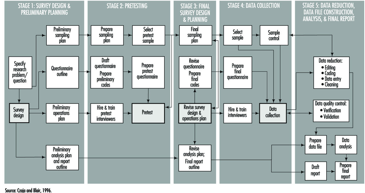
Types of studies and questionnaires
The research goals of the study itself determine the structure, length and content of the questionnaire. These questionnaire attributes are invariably tempered by the method of data collection, which usually falls within one of three modes: in person, mail and telephone. Each of these has its advantages and disadvantages which can affect not only the quality of the data but the validity of the overall study.
A mailed questionnaire is the least expensive format and can cover workers in a wide geographical area. However, in that overall response rates are often low (typically 45 to 75%), it cannot be overly complex since there is little or no opportunity for clarification of questions, and it may be difficult to ascertain whether potential responses to critical exposure or other questions differ systematically between respondents and non-respondents. The physical layout and language must accommodate the least educated of potential study participants, and must be capable of completion in a fairly short time period, typically 20 to 30 minutes.
Telephone questionnaires can be used in population-based studies—that is, surveys in which a sample of a geographically defined population is canvassed—and are a practical method to update information in existing data files. They may be longer and more complex than mailed questionnaires in language and content, and since they are administered by trained interviewers the greater cost of a telephone survey can be partially offset by physically structuring the questionnaire for efficient administration (such as through skip patterns). Response rates are usually better than with mailed questionnaires, but are subject to biases related to increasing use of telephone answering machines, refusals, non-contacts and problems of populations with limited telephone service. Such biases generally relate to the sampling design itself and not especially to the questionnaire. Although telephone questionnaires have long been in use in North America, their feasibility in other parts of the world has yet to be established.
Face-to-face interviews provide the greatest opportunity for collecting accurate complex data; they are also the most expensive to administer, since they require both training and travel for professional staff. The physical layout and order of questions may be arranged to optimize administration time. Studies which utilize in-person interviewing generally have the highest response rates and are subject to the least response bias. This is also the type of interview in which the interviewer is most likely to learn whether or not the participant is a case (in a case-control study) or the participant’s exposure status (in a cohort study). Care must therefore be taken to preserve the objectivity of the interviewer by training him or her to avoid leading questions and body language that might evoke biased responses.
It is becoming more common to use a hybrid study design in which complex exposure situations are assessed in a personal or telephone interview which allows maximum probing and clarification, followed by a mailed questionnaire to capture lifestyle data like smoking and diet.
Confidentiality and research participant issues
Since the purpose of a questionnaire is to obtain data about individuals, questionnaire design must be guided by established standards for ethical treatment of human subjects. These guidelines apply to acquisition of questionnaire data just as they do for biological samples such as blood and urine, or to genetic testing. In the United States and many other countries, no studies involving humans may be conducted with public funds unless approval of questionnaire language and content is first obtained from an appropriate Institutional Review Board. Such approval is intended to assure that questions are confined to legitimate study purposes, and that they do not violate the rights of study participants to answer questions voluntarily. Participants must be assured that their participation in the study is entirely voluntary, and that refusal to answer questions or even to participate at all will not subject them to any penalties or alter their relationship with their employer or medical practitioner.
Participants must also be assured that the information they provide will be held in strict confidence by the investigator, who must of course take steps to maintain the physical security and inviolability of the data. This often entails physical separation of information regarding the identity of participants from computerized data files. It is common practice to advise study participants that their replies to questionnaire items will be used only in aggregation with responses of other participants in statistical reports, and will not be disclosed to the employer, physician or other parties.
Measurement aspects of questionnaire design
One of the most important functions of a questionnaire is to obtain data about some aspect or attribute of a person in either qualitative or quantitative form. Some items may be as simple as weight, height or age, while others may be considerably more complicated, as with an individual’s response to stress. Qualitative responses, such as gender, will ordinarily be converted into numerical variables. All such measures may be characterized by their validity and their reliability. Validity is the degree to which a questionnaire-derived number approaches its true, but possibly unknown, value. Reliability measures the likelihood that a given measurement will yield the same result on repetition, whether that result is close to the “truth” or not. Figure 2 shows how these concepts are related. It demonstrates that a measurement can be valid but not reliable, reliable but not valid, or both valid and reliable.
Figure 2. Validity & reliability relationship

Over the years, many questionnaires have been developed by researchers in order to answer research questions of wide interest. Examples include the Scholastic Aptitude Test, which measures a student’s potential for future academic achievement, and the Minnesota Multiphasic Personality Inventory (MMPI), which measures certain psychosocial characteristics. A variety of other psychological indicators are discussed in the chapter on psychometrics. There are also established physiological scales, such as the British Medical Research Council (BMRC) questionnaire for pulmonary function. These instruments have a number of important advantages. Chief among these are the facts that they have already been developed and tested, usually in many populations, and that their reliability and validity are known. Anyone constructing a questionnaire is well advised to utilize such scales if they fit the study purpose. Not only do they save the effort of “re-inventing the wheel”, but they make it more likely that study results will be accepted as valid by the research community. It also makes for more valid comparisons of results from different studies provided they have been properly used.
The preceding scales are examples of two important types of measures which are commonly used in questionnaires to quantify concepts that may not be fully objectively measurable in the way that height and weight are, or which require many similar questions to fully “tap the domain” of one specific behavioural pattern. More generally, indexes and scales are two data reduction techniques that provide a numerical summary of groups of questions. The above examples illustrate physiological and psychological indexes, and they are also frequently used to measure knowledge, attitude and behaviour. Briefly, an index is usually constructed as a score obtained by counting, among a group of related questions, the number of items that apply to a study participant. For instance, if a questionnaire presents a list of diseases, a disease history index could be the total number of those which a respondent says he or she has had. A scale is a composite measure based on the intensity with which a participant answers one or more related questions. For example, the Likert scale, which is frequently used in social research, is typically constructed from statements with which one may agree strongly, agree weakly, offer no opinion, disagree weakly, or disagree strongly, the response being scored as a number from 1 to 5. Scales and indexes may be summed or otherwise combined to form a fairly complex picture of study participants’ physical, psychological, social or behavioural characteristics.
Validity merits special consideration because of its reflection of the “truth”. Three important types of validity often discussed are face, content and criterion validity. Face validity is a subjective quality of an indicator which insures that the wording of a question is clear and unambiguous. Content validity insures that the questions will serve to tap that dimension of response in which the researcher is interested. Criterion (or predictive) validity is derived from an objective assessment of how closely a questionnaire measurement approaches a separately measurable quantity, as for instance how well a questionnaire assessment of dietary vitamin A intake matches the actual consumption of vitamin A, based upon food consumption as documented with dietary records.
Questionnaire content, quality and length
Wording. The wording of questions is both an art and a professional skill. Therefore, only the most general of guidelines can be presented. It is generally agreed that questions should be devised which:
- motivate the participant to respond
- draw upon the participant’s personal knowledge
- take into account his or her limitations and personal frame of reference, so that the aim and meaning of the questions is easily understood and
- elicit a response based upon the participant’s own knowledge and do not require guessing, except possibly for attitude and opinion questions.
Question sequence and structure. Both the order and presentation of questions can affect the quality of information gathered. A typical questionnaire, whether self-administered or read by an interviewer, contains a prologue which introduces the study and its topic to the respondent, provides any additional information he or she will need, and tries to motivate the respondent to answer the questions. Most questionnaires contain a section designed to collect demographic information, such as age, gender, ethnic background and other variables about the participant’s background, including possibly confounding variables. The main subject matter of data collection, such as nature of the workplace and exposure to specific substances, is usually a distinct questionnaire section, and is often preceded by an introductory prologue of its own which might first remind the participant of specific aspects of the job or workplace in order to create a context for detailed questions. The layout of questions that are intended to establish worklife chronologies should be arranged so as to minimize the risk of chronological omissions. Finally, it is customary to thank the respondent for his or her participation.
Types of questions. The designer must decide whether to use open-ended questions in which participants compose their own answers, or closed questions that require a definite response or a choice from a short menu of possible responses. Closed questions have the advantage that they clarify alternatives for the respondent, avoid snap responses, and minimize lengthy rambling that may be impossible to interpret. However, they require that the designer anticipate the range of potential responses in order to avoid losing information, particularly for unexpected situations that occur in many workplaces. This in turn requires well planned pilot testing. The investigator must decide whether and to what extent to permit a “don’t know” response category.
Length. Determining the final length of a questionnaire requires striking a balance between the desire to obtain as much detailed information as possible to achieve the study goals with the fact that if a questionnaire is too lengthy, at some point many respondents will lose interest and either stop responding or respond hastily, inaccurately and without thought in order to bring the session to an end. On the other hand, a questionnaire which is very short may obtain a high response rate but not achieve the study goals. Since respondent motivation often depends on having a personal stake in the outcome, such as improving working conditions, tolerance for a lengthy questionnaire may vary widely, especially when some participants (such as workers in a particular plant) may perceive their stake to be higher than others (such as persons contacted via random telephone dialling). This balance can be achieved only through pilot testing and experience. Interviewer-administered questionnaires should record the beginning and ending time to permit calculation of the duration of the interview. This information is useful in assessing the level of quality of the data.
Language. It is essential to use the language of the population to make the questions understood by all. This may require becoming familiar with local vernacular that may vary within any one country. Even in countries where the same language is nominally spoken, such as Britain and the United States, or the Spanish-speaking countries of Latin America, local idioms and usage may vary in a way that can obscure interpretation. For example, in the US “tea” is merely a beverage, whereas in Britain it may mean “a pot of tea,” “high tea,” or “the main evening meal,” depending on locale and context. It is especially important to avoid scientific jargon, except where study participants can be expected to possess specific technical knowledge.
Clarity and leading questions. While it is often the case that shorter questions are clearer, there are exceptions, especially where a complex subject needs to be introduced. Nevertheless, short questions clarify thinking and reduce unnecessary words. They also reduce the chance of overloading the respondent with too much information to digest. If the purpose of the study is to obtain objective information about the participant’s working situation, it is important to word questions in a neutral way and to avoid “leading” questions that may favour a particular answer, such as “Do you agree that your workplace conditions are harmful to your health?”
Questionnaire layout. The physical layout of a questionnaire can affect the cost and efficiency of a study. It is more important for self-administered questionnaires than those which are conducted by interviewers. A questionnaire which is designed to be completed by the respondent but which is overly complex or difficult to read may be filled out casually or even discarded. Even questionnaires which are designed to be read aloud by trained interviewers need to be printed in clear, readable type, and patterns of question skipping must be indicated in a manner which maintains a steady flow of questioning and minimizes page turning and searching for the next applicable question.
Validity Concerns
Bias
The enemy of objective data gathering is bias, which results from systematic but unplanned differences between groups of people: cases and controls in a case-control study or exposed and non-exposed in a cohort study. Information bias may be introduced when two groups of participants understand or respond differently to the same question. This may occur, for instance, if questions are posed in such a way as to require special technical knowledge of a workplace or its exposures that would be understood by exposed workers but not necessarily by the general public from which controls are drawn.
The use of surrogates for ill or deceased workers has the potential for bias because next-of-kin are likely to recall information in different ways and with less accuracy than the worker himself or herself. The introduction of such bias is especially likely in studies in which some interviews are carried out directly with study participants while other interviews are carried out with relatives or co-workers of other research participants. In either situation, care must be taken to reduce any effect that might arise from the interviewer’s knowledge of the disease or exposure status of the worker of interest. Since it is not always possible to keep interviewers “blind,” it is important to emphasize objectivity and avoidance of leading or suggestive questions or unconscious body language during training, and to monitor performance while the study is being carried out.
Recall bias results when cases and controls “remember” exposures or work situations differently. Hospitalized cases with a potential occupationally related illness may be more capable of recalling details of their medical history or occupational exposures than persons contacted randomly on the telephone. A type of this bias that is becoming more common has been labelled social desirability bias. It describes the tendency of many people to understate, whether consciously or not, their indulgence in “bad habits” such as cigarette smoking or consumption of foods high in fat and cholesterol, and to overstate “good habits” like exercise.
Response bias denotes a situation in which one group of study participants, such as workers with a particular occupational exposure, may be more likely to complete questionnaires or otherwise participate in a study than unexposed persons. Such a situation may result in a biased estimation of the association between exposure and disease. Response bias may be suspected if response rates or the time taken to complete a questionnaire or interview differ substantially between groups (e.g., cases vs. controls, exposed vs. unexposed). Response bias generally differs depending upon the mode of questionnaire administration. Questionnaires which are mailed are usually more likely to be returned by individuals who see a personal stake in study findings, and are more likely to be ignored or discarded by persons selected at random from the general population. Many investigators who utilize mail surveys also build in a follow-up mechanism which may include second and third mailings as well as subsequent telephone contacts with non-respondents in order to maximize response rates.
Studies which utilize telephone surveys, including those which make use of random digit dialling to identify controls, usually have a set of rules or a protocol defining how many times attempts to contact potential respondents must be made, including time of day, and whether evening or weekend calls should be attempted. Those who conduct hospital-based studies usually record the number of patients who refuse to participate, and reasons for non-participation. In all such cases, various measures of response rates are recorded in order to provide an assessment of the extent to which the target population has actually been reached.
Selection bias results when one group of participants preferentially responds or otherwise participates in a study, and can result in biased estimation of the relationship between exposure and disease. In order to assess selection bias and whether it leads to under- or over-estimation of exposure, demographic information such as educational level can be used to compare respondents with non-respondents. For example, if participants with little education have lower response rates than participants with higher education, and if a particular occupation or smoking habit is known to be more frequent in less educated groups, then selection bias with underestimation of exposure for that occupation or smoking category is likely to have occurred.
Confounding is an important type of selection bias which results when the selection of respondents (cases and controls in a case-control study, or exposed and unexposed in a cohort study) depends in some way upon a third variable, sometimes in a manner unknown to the investigator. If not identified and controlled, it can lead unpredictably to underestimates or overestimates of disease risks associated with occupational exposures. Confounding is usually dealt with either by manipulating the design of the study itself (e.g., through matching cases to controls on age and other variables) or at the analysis stage. Details of these techniques are presented in other articles within this chapter.
Documentation
In any research study, all study procedures must be thoroughly documented so that all staff, including interviewers, supervisory personnel and researchers, are clear about their respective duties. In most questionnaire-based studies, a coding manual is prepared which describes on a question-by-question basis everything the interviewer needs to know beyond the literal wording of the questions. This includes instructions for coding categorical responses and may contain explicit instructions on probing, listing those questions for which it is permitted and those for which it is not. In many studies new, unforeseen response choices for certain questions are occasionally encountered in the field; these must be recorded in the master codebook and copies of additions, changes or new instructions distributed to all interviewers in a timely fashion.
Planning, testing and revision
As can be seen from figure 1, questionnaire development requires a great deal of thoughtful planning. Every questionnaire needs to be tested at several stages in order to make certain that the questions “work”, i.e., that they are understandable and produce responses of the intended quality. It is useful to test new questions on volunteers and then to interrogate them at length to determine how well specific questions were understood and what types of problems or ambiguities were encountered. The results can then be utilized to revise the questionnaire, and the procedure can be repeated if necessary. The volunteers are sometimes referred to as a “focus group”.
All epidemiological studies require pilot testing, not only for the questionnaires, but for the study procedures as well. A well designed questionnaire serves its purpose only if it can be delivered efficiently to the study participants, and this can be determined only by testing procedures in the field and making adjustments when necessary.
Interviewer training and supervision
In studies which are conducted by telephone or face-to-face interview, the interviewer plays a critical role. This person is responsible not simply for presenting questions to the study participants and recording their responses, but also for interpreting those responses. Even with the most rigidly structured interview study, respondents occasionally request clarification of questions, or offer responses which do not fit the available response categories. In such cases the interviewer’s job is to interpret either the question or the response in a manner consistent with the intent of the researcher. To do so effectively and consistently requires training and supervision by an experienced researcher or manager. When more than one interviewer is employed on a study, interviewer training is especially important to insure that questions are presented and responses interpreted in a uniform manner. In many research projects this is accomplished in group training settings, and is repeated periodically (e.g., annually) in order to keep the interviewers’ skills fresh. Training seminars commonly cover the following topics in considerable detail:
- general introduction to the study
- informed consent and confidentiality issues
- how to introduce the interview and how to interact with respondents
- the intended meaning of each question
- instructions for probing, i.e., offering the respondent further opportunity to clarify or embellish responses
- discussion of typical problems which arise during interviews.
Study supervision often entails onsite observation, which may include tape-recording of interviews for subsequent dissection. It is common practice for the supervisor to personally review every questionnaire prior to approving and submitting it to data entry. The supervisor also sets and enforces performance standards for interviewers and in some studies conducts independent re-interviews with selected participants as a reliability check.
Data collection
The actual distribution of questionnaires to study participants and subsequent collection for analysis is carried out using one of the three modes described above: by mail, telephone or in person. Some researchers organize and even perform this function themselves within their own institutions. While there is considerable merit to a senior investigator becoming familiar with the dynamics of the interview at first hand, it is most cost effective and conducive to maintaining high data quality for trained and well-supervised professional interviewers to be included as part of the research team.
Some researchers make contractual arrangements with companies that specialize in survey research. Contractors can provide a range of services which may include one or more of the following tasks: distributing and collecting questionnaires, carrying out telephone or face-to-face interviews, obtaining biological specimens such as blood or urine, data management, and statistical analysis and report writing. Irrespective of the level of support, contractors are usually responsible for providing information about response rates and data quality. Nevertheless, it is the researcher who bears final responsibility for the scientific integrity of the study.
Reliability and re-interviews
Data quality may be assessed by re-interviewing a sample of the original study participants. This provides a means for determining the reliability of the initial interviews, and an estimate of the repeatability of responses. The entire questionnaire need not be re-administered; a subset of questions usually is sufficient. Statistical tests are available for assessing the reliability of a set of questions asked of the same participant at different times, as well as for assessing the reliability of responses provided by different participants and even for those queried by different interviewers (i.e., inter- and intra-rater assessments).
Technology of questionnaire processing
Advances in computer technology have created many different ways in which questionnaire data can be captured and made available to the researcher for computer analysis. There are three fundamentally different ways in which data can be computerized: in real time (i.e., as the participant responds during an interview), by traditional key entry methods, and by optical data capture methods.
Computer-aided data capture
Many researchers now use computers to collect responses to questions posed in both face-to-face and telephone interviews. Researchers in the field find it convenient to use laptop computers which have been programmed to display the questions sequentially and which permit the interviewer to enter the response immediately. Survey research companies which do telephone interviewing have developed analogous systems called computer-aided telephone interview (CATI) systems. These methods have two important advantages over more traditional paper questionnaires. First, responses can be instantly checked against a range of permissible answers and for consistency with previous responses, and discrepancies can be immediately brought to the attention of both the interviewer and the respondent. This greatly reduces the error rate. Secondly, skip patterns can be programmed to minimize administration time.
The most common method for computerizing data still is the traditional key entry by a trained operator. For very large studies, questionnaires are usually sent to a professional contract company which specializes in data capture. These firms often utilize specialized equipment which permits one operator to key a questionnaire (a procedure sometimes called keypunch for historical reasons) and a second operator to re-key the same data, a process called key verification. Results of the second keying are compared with the first to assure the data have been entered correctly. Quality assurance procedures can be programmed which ensure that each response falls within an allowable range, and that it is consistent with other responses. The resulting data files can be transmitted to the researcher on disk, tape or electronically by telephone or other computer network.
For smaller studies, there are numerous commercial PC-based programs which have data entry features which emulate those of more specialized systems. These include database programs such as dBase, Foxpro and Microsoft Access, as well as spreadsheets such as Microsoft Excel and Lotus 1-2-3. In addition, data entry features are included with many computer program packages whose principal purpose is statistical data analysis, such as SPSS, BMDP and EPI INFO.
One widespread method of data capture which works well for certain specialized questionnaires uses optical systems. Optical mark reading or optical sensing is used to read responses on questionnaires that are specially designed for participants to enter data by marking small rectangles or circles (sometimes called “bubble codes”). These work most efficiently when each individual completes his or her own questionnaire. More sophisticated and expensive equipment can read hand-printed characters, but at present this is not an efficient technique for capturing data in large-scale studies.
Archiving Questionnaires and Coding Manuals
Because information is a valuable resource and is subject to interpretation and other influences, researchers sometimes are asked to share their data with other researchers. The request to share data can be motivated by a variety of reasons, which may range from a sincere interest in replicating a report to concern that data may not have been analysed or interpreted correctly.
Where falsification or fabrication of data is suspected or alleged, it becomes essential that the original records upon which reported findings are based be available for audit purposes. In addition to the original questionnaires and/or computer files of raw data, the researcher must be able to provide for review the coding manual(s) developed for the study and the log(s) of all data changes which were made in the course of data coding, computerization and analysis. For example, if a data value had been altered because it had initially appeared as an outlier, then a record of the change and the reasons for making the change should have been recorded in the log for possible data audit purposes. Such information also is of value at the time of report preparation because it serves as a reminder about how the data which gave rise to the reported findings had actually been handled.
For these reasons, upon completion of a study, the researcher has an obligation to ensure that all basic data are appropriately archived for a reasonable period of time, and that they could be retrieved if the researcher were called upon to provide them.
Occupational Nail Dystrophy
The function of the epithelium of the epidermis is to form the surface or horny layer of the skin, of which the major component is the fibrous protein, keratin. In certain areas the epithelium is specially developed to produce a particular type of keratin structure. One of these is hair, and another is nail. The nail plate is formed partly by the epithelium of the matrix and partly by that of the nail bed. The nail grows in the same way as the hair and the horny layer and is affected by similar pathogenic mechanisms to those responsible for diseases of the hair and epidermis. Some elements such as arsenic and mercury accumulate in the nail as in the hair.
Figure 1 shows that the nail matrix is an invagination of the epithelium and it is covered by the nail fold at its base. A thin film of horny layer called the cuticle serves to seal the paronychial space by stretching from the nail fold to the nail plate.
Figure 1. The structure of the nail.

The most vulnerable parts of the nail are the nail fold and the area beneath the tip of the nail plate, although the nail plate itself may suffer direct physical or chemical traumata. Chemical substances or infective agents may penetrate under the nail plate at its free margin. Moisture and alkali may destroy the cuticle and allow the entry of bacteria and fungi which will cause inflammation of the paronychial tissue and produce secondary growth disturbance of the nail plate.
The most frequent causes of nail disease are chronic paronychia, ringworm, trauma, psoriasis, impaired circulation and eczema or other dermatitis. Paronychia is an inflammation of the nail fold. Acute paronychia is a painful suppurative condition requiring antibiotic and sometimes surgical treatment. Chronic paronychia follows loss of the cuticle which allows water, bacteria and Candida albicans to penetrate into the paronychial space. It is common among persons with intense exposure to water, alkaline substances and detergents, such as kitchen staff, cleaners, fruit and vegetable preparers and canners and housewives. Full recovery cannot be achieved until the integrity of the cuticle and eponychium sealing the paronychial space has been restored.
Exposure to cement, lime and organic solvents, and work such as that of a butcher or poulterer may also cause trauma of the cuticle and nail folds.
Any inflammation or disease of the nail matrix may result in dystrophy (distortion) of the nail plate, which is usually the symptom which has brought the condition to medical attention. Exposure to chilling cold, or the arterial spasm of Raynaud’s phenomenon, can also damage the matrix and produce nail dystrophy. Sometimes the damage is temporary and the nail dystrophy will disappear after removal of the cause and treatment of the inflammatory condition. (An example is shown in figure 2.)
Figure 2. Onychodystrophy secondary to contact dermatitis resulting from chronic irritation.

One cause of nail damage is the direct application of certain cosmetic preparations, such as base coats under nail polish, nail hardeners and synthetic nail dressings to the nail.
Some special occupations may cause nail damage. There has been a report of dystrophy due to handling the concentrated dipyridylium pesticide compounds paraquat and diquat. During the manufacture of selenium dioxide, a fine powder of this substance may get under the fringe of the nail plate and cause intense irritation and necrosis of the finger tip and damage to the nail plate. Care should be taken to warn workers of this hazard and advise them always to clean the subungual areas of their fingers each day.
Certain types of allergic contact dermatitis of the finger tips frequently result in secondary nail dystrophy. Six common sensitizers which will do this are:
- amethocaine and chemically related local anaesthetics used by dental surgeons
- formalin used by mortuary attendants, anatomy, museum and laboratory assistants
- garlic and onion used by cooks
- tulip bulbs and flowers handled by horticulturists and florists
- p-tert-butylphenol formaldehyde resin used by shoe manufacturers and repairers
- aminoethylethanolamine used in some aluminium fluxes.
The diagnosis can be confirmed by a positive patch test. The condition of the skin and nails will recover when contact ceases.
Protective measures
In many cases nails can be safeguarded by the use of suitable hand protection. However, where hand exposure exists, nails should receive adequate care, consisting essentially of preserving the cuticle and protecting the subungual area. The skin under the free margin of the nails should be cleaned daily in order to remove foreign debris or chemical irritants. Where barrier creams or lotions are employed, care should be taken to ensure that the cuticle and the area under the free margin are coated.
To preserve the intact cuticle it is necessary to avoid excessive manicure or trauma, maceration by prolonged exposure to water, and dissolution by repeated exposure to alkali, solvent and detergent solutions.
Prevention of Occupational Dermatoses
The goal of occupational health programmes is to allow workers to maintain their job and their health over several years. The development of effective programmes requires the identification of sectoral, population-based, and workplace-specific risk factors. This information can then be used to develop prevention policies both for groups and individuals.
The Québec Occupational Health and Safety Commission (Commission de la santé et de la sécurité au travail du Québec) has characterized work activities in 30 industrial, commercial, and service sectors (Commission de la santé et de la sécurité au travail 1993). Its surveys reveal that occupational dermatoses are most prevalent in the food and beverage industries, medical and social services, miscellaneous commercial and personal services and construction (including public works). Affected workers are typically engaged in service, manufacturing, assembly, repair, materials handling, food-processing, or health-care activities.
Occupational dermatoses are particularly prevalent in two age groups: young and inexperienced workers who may be unaware of the sometimes insidious risks associated with their work, and those workers approaching retirement age who may not have noticed the progressive drying of their skin over the years, which increases over several consecutive workdays. Because of such dehydration, repeated exposure to previously well-tolerated irritant or astringent substances may cause irritative dermatitis in these workers.
As table 1 indicates, even though most cases of occupational dermatoses do not involve compensation exceeding two weeks, a significant number of cases may persist for over two months (Durocher and Paquette 1985). This table clearly illustrates the importance of preventing chronic dermatoses requiring prolonged work absences.
Table 1. Occupational dermatoses in Quebec in 1989: Distribution by length of compensation
|
Length of compensation (days) |
0 |
1–14 |
15–56 |
57–182 |
>183 |
|
Number of cases (total: 735) |
10 |
370 |
195 |
80 |
80 |
Source: Commission de la santé et de la sécurité au travail, 1993.
Risk Factors
Many substances used in industry are capable of causing dermatoses, the risk of which depends on the concentration of the substance and the frequency and duration of skin contact. The general classification scheme presented in table 2 (overleaf) based on the classification of risk factors as mechanical, physical, chemical or biological, is a useful tool for the identification of risk factors during site visits. During workplace evaluation, the presence of risk factors may be either directly observed or suspected on the basis of observed skin lesions. Particular attention is paid to this in the classification scheme presented in table 2. In some cases effects specific to a given risk factor may be present, while in others, the skin disorders may be associated with several factors in a given category. Disorders of this last type are known as group effects. The specific cutaneous effects of physical factors are listed in table 2 and described in other sections of this chapter.
Table 2. Risk factors and their effects on the skin
Mechanical factors
Trauma
Friction
Pressure
Dusts
Physical factors
Radiation
Humidity
Heat
Cold
Chemical factors
Acids, bases
Detergents, solvents
Metals, resins
Cutting oils
Dyes, tar
Rubber, etc.
Biological factors
Bacteria
Viruses
Dermatophytes
Parasites
Plants
Insects
Risk co-factors
Eczema (atopic, dyshidrotic, seborrhoeic, nummular)
Psoriasis
Xeroderma
Acne
Group effects
Cuts, punctures, blisters
Abrasions, isomorphism
Lichenification
Calluses
Specific effects
Photodermatitis, radiodermatitis, cancer
Maceration, irritation
Heat rash, burns, erythema
Frostbite, xeroderma, urticaria, panniculitis, Raynaud’s phenomenon
Group effects
Dehydration
Inflammation
Necrosis
Allergy
Photodermatitis
Dyschromia
Specific effects
Pyodermatitis
Multiple warts
Dermatomycosis
Parasitosis
Phytodermatitis
Urticaria
Mechanical factors include repeated friction, excessive and prolonged pressure, and the physical action of some industrial dusts, whose effects are a function of the shape and size of the dust particles and the extent of their friction with the skin. The injuries themselves may be mechanical (especially in workers exposed to repeated vibrations), chemical, or thermal, and include physical lesions (ulcers, blisters), secondary infection, and isomorphism (Koebner phenomenon). Chronic changes, such as scars, keloid, dyschromia, and Raynaud’s phenomenon, which is a peripheral neurovascular alteration caused by prolonged use of vibrating tools, may also develop.
Chemical factors are by far the most common cause of occupational dermatoses. To establish an exhaustive list of the many chemicals is not practical. They may cause allergic, irritant or photodermatotic reactions, and may leave dyschromic sequelae. The effects of chemical irritation vary from simple drying to inflammation to complete cell necrosis. More information on this subject is provided in the article on contact dermatitis. Material Safety Data Sheets, which provide toxicological and other information are indispensable tools for developing effective preventive measures against chemicals. Several countries, in fact, require chemical manufacturers to provide every workplace using their products with information on the occupational health hazards posed by their products.
Bacterial, viral and fungal infections contracted in the workplace arise from contact with contaminated materials, animals, or people. Infections include pyodermatitis, folliculitis, panaris, dermatomycosis, anthrax, and brucellosis. Workers in the food-processing sector may develop multiple warts on their hands, but only if they have already suffered microtraumas and are exposed to excessive levels of humidity for prolonged periods (Durocher and Paquette 1985). Both animals and humans such as day-care and health-care workers, may act as vectors for parasitic contamination like mites, scabies and head lice. Phytodermatitis may be caused by plants (Rhus sp.) or flowers (alstromeria, chrysanthemums, tulips). Finally, some wood extracts may cause contact dermatitis.
Risk Co-factors
Some non-occupational cutaneous pathologies may exacerbate the effects of environmental factors on workers’ skin. For example, it has long been recognized that the risk of irritant contact dermatitis is greatly increased in individuals with a medical history of atopy, even in the absence of an atopic dermatitis. In a study of 47 cases of irritant contact dermatitis of the hands of food-processing workers, 64% had a history of atopy (Cronin 1987). Individuals with atopic dermatitis have been shown to develop more severe irritation when exposed to sodium lauryl sulphate, commonly found in soaps (Agner 1991). Predisposition to allergies (Type I) (atopic diathesis) does not however increase the risk of delayed allergic (Type IV) contact dermatitis, even to nickel (Schubert et al. 1987), the allergen most commonly screened for. On the other hand, atopy has recently been shown to favour the development of contact urticaria (Type I allergy) to rubber latex among health-care workers (Turjanmaa 1987; Durocher 1995) and to fish among caterers (Cronin 1987).
In psoriasis, the outmost layer of the skin (stratum corneum) is thickened but not calloused (parakeratotic) and less resistant to skin irritants and mechanical traction. Frequent skin injury may worsen pre-existing psoriasis, and new isomorphic psoriatic lesions may develop on scar tissue.
Repeated contact with detergents, solvents, or astringent dusts may lead to secondary irritant contact dermatitis in individuals suffering from xeroderma. Similarly, exposure to frying oils may exacerbate acne.
Prevention
A thorough understanding of relevant risk factors is a prerequisite to establishing prevention programmes, which may be either institutional or personal ones such as relying on personal protective equipment. The efficacy of prevention programmes depends on the close collaboration of workers and employers during their development. Table 3 provides some information on prevention.
Table 3. Collective measures (group approach) to prevention
Collective measures
- Substitution
- Environmental control:
Use of tools for handling materials
Ventilation
Closed systems
Automation
- Information and training
- Careful work habits
- Follow-up
Personal protection
- Skin hygiene
- Protective agents
- Gloves
Workplace Prevention
The primary goal of workplace preventive measures is the elimination of hazards at their source. When feasible, substitution of a toxic substance by a non-toxic one is the ideal solution. For example, the toxic effects of a solvent being incorrectly used to clean the skin can be eliminated by substituting a synthetic detergent that presents no systemic hazard and that is less irritating. Several non-allergenic cement powders which substitute ferrous sulphate for hexavalent chromium, a well-known allergen, are now available. In water-based cooling systems, chromate-based anti-corrosion agents can be replaced by zinc borate, a weaker allergen (Mathias 1990). Allergenic biocides in cutting oils can be replaced by other preservatives. The use of gloves made of synthetic rubber or PVC can eliminate the development of latex allergies among health-care workers. Replacement of aminoethanolamine by triethanolamine in welding fluxes used to weld aluminium cables has led to a reduction in allergies (Lachapelle et al. 1992).
Modification of production processes to avoid skin contact with hazardous substances may be an acceptable alternative when substitution is impossible or the risk is low. Simple modifications include using screens or flexible tubes to eliminate splashing during the transfer of liquids, or filters that retain residues and reduce the need for manual cleaning. More natural grasp points on tools and equipment that avoid exerting excessive pressure and friction on the hands and that prevent skin contact with irritants may also work. Local capture ventilation with capture inlets that limit nebulisation or reduce the concentration of airborne dusts are useful. Where processes have been completely automated in order to avoid environmental hazards, particular attention should be paid to training workers responsible for repairing and cleaning the equipment and specific preventive measures may be required to limit their exposure (Lachapelle et al. 1992).
All personnel must be aware of the hazards present in their workplace, and collective measures can only be effective when implemented in conjunction with a comprehensive information programme. Material Safety Data Sheets can be used to identify hazardous and potentially hazardous substances. Hazard warning signs can be used to rapidly identify these substances. A simple colour code allows visual coding of the risk level. For example, a red sticker could signal the presence of a hazard and the necessity of avoiding direct skin contact. This code would be appropriate for a corrosive substance that rapidly attacks the skin. Similarly, a yellow sticker could indicate the need for prudence, for example when dealing with a substance capable of damaging the skin following repeated or prolonged contact (Durocher 1984). Periodic display of posters and the occasional use of audio-visual aids reinforce the information delivered and stimulate interest in occupational dermatosis prevention programmes.
Complete information on the hazards associated with work activities should be provided to workers prior to starting work. In several countries, workers are given special occupational training by professional instructors.
Workplace training must be repeated each time a process or task is changed with resulting change in risk factors. Neither an alarmist nor paternalistic attitude favours good working relationships. Employers and workers are partners who both desire work to be executed safely, and the information delivered will only be credible if it is realistic.
Given the absence of safety standards for dermatotoxic substances (Mathias 1990), preventive measures must be supported by vigilant observation of the state of workers’ skin. Fortunately this is easily implemented, since the skin, particularly that on the hands and face, can be directly observed by everyone. The goal of this type of observation is the identification of early signs of cutaneous modifications indicating an overwhelming of the body’s natural equilibrium. Workers and health and safety specialists should therefore be on the lookout for the following early warning signs:
- progressive drying
- maceration
- localized thickening
- frequent trauma
- redness, particularly around hairs.
Prompt identification and treatment of cutaneous pathologies is essential, and their underlying causal factors must be identified, to prevent them from becoming chronic.
When workplace controls are unable to protect the skin from contact with hazardous substances, the duration of skin contact should be minimized. For this purpose, workers should have ready access to appropriate hygienic equipment. Contamination of cleaning agents can be avoided by using closed containers equipped with a pump that dispenses an adequate amount of the cleanser with a single press. Selecting cleansers requires compromising between cleaning power and the potential for irritation. For example, so-called high-performance cleansers often contain solvents or abrasives which increase irritation. The cleanser selected should take into account the specific characteristics of the workplace, since workers will often simply use a solvent if available cleansers are ineffective. Cleansers may take the form of soaps, synthetic detergents, waterless pastes or creams, abrasive preparations and antimicrobial agents (Durocher 1984).
In several occupations, the application of a protective cream before work facilitates skin cleaning, regardless of the cleaner used. In all cases, the skin must be thoroughly rinsed and dried after each washing. Failure to do so may increase irritation, for example by re-emulsification of the soap residues caused by the humidity inside impermeable gloves.
Industrial soaps are usually provided as liquids dispensed by hand pressure. They are composed of fatty acids of animal (lard) or vegetable (oil) origin, buffered with a base (e.g., sodium hydroxide). Buffering may be incomplete and may leave residual free radicals that are capable of irritating the skin. To avoid this, a near-neutral pH (4 to 10) is desirable. These liquid soaps are adequate for many tasks.
Synthetic detergents, available in both liquid and powder form, emulsify greases. Thus they usually remove the human skin’s sebum, which is a substance that protects the skin against drying. Skin emulsification is generally less marked with soaps than with synthetic detergents and is proportional to detergent concentration. Emollients such as glycerine, lanolin, and lecithin are often added to detergents to counteract this effect.
Pastes and creams, also known as “waterless soaps” are emulsions of oil-based substances in water. Their primary cleaning agent is a solvent, generally a petroleum derivative. They are called “waterless” because they are effective in the absence of tap water, and are typically used to remove stubborn soils or to wash hands when water is unavailable. Because of their harshness, they are not considered cleansers of choice. Recently, “waterless soaps” containing synthetic detergents that are less irritating to the skin than solvents have become available. The American Association of Soap and Detergent Manufacturers recommends washing with a mild soap after using solvent-based “waterless soaps.” Workers who use “waterless soaps” three or four times per day should apply a moisturizing lotion or cream at the end of the work day, in order to prevent drying.
Abrasive particles, which are often added to one of the cleaners described above to increase their cleaning power are irritants. They may be soluble (e.g., borax) or insoluble. Insoluble abrasives may be mineral (e.g., pumice), vegetal (e.g., nut shells) or synthethic (e.g., polystyrene).
Antimicrobial cleaners should only be used in workplaces where there is a real risk of infection, since several of them are potential allergens and workers should not be exposed needlessly.
Under the influence of certain substances or repeated washings, workers’ hands may tend to dry out. Long-term maintenance of good skin hygiene under these conditions requires daily moisturizing, the frequency of which will depend on the individual and the type of work. In many cases, moisturizing lotions or creams, also known as hand creams, are adequate. In cases of severe drying or when the hands are immersed for prolonged periods, hydrophilic vaselines are more appropriate. So-called protective or barrier creams are usually moisturizing creams; they may contain silicones or zinc or titanium oxides. Exposure-specific protective creams are rare, with the exception of those which protect against ultraviolet radiation. These have been greatly improved over the last few years and now provide effective protection against both UV-A and UV-B. A minimum protection factor of 15 (North American scale) is recommended. StokogarÔ cream appears to be effective against contact dermatitis caused by poison ivy. Protective or barrier creams should never be seen as equivalent to some form of invisible impermeable glove (Sasseville 1995). Furthermore, protective creams are only effective on healthy skin.
While few people like wearing protective equipment, there may be no choice when the measures described above are inadequate. Protective equipment includes: boots, aprons, visors, sleeves, overalls, shoes, and gloves. These are discussed elsewhere in the Encyclopaedia.
Many workers complain that protective gloves reduce their dexterity, but their use is nevertheless inevitable in some situations. Special efforts are required to minimize their inconvenience. Many types are available, both permeable (cotton, leather, metal mesh, KevlaÔasbestos) and impermeable (rubber latex, neoprene, nitrile, polyvinyl chloride, VitoÔ, polyvinyl alcohol, polyethylene) to water. The type selected should take into account the specific needs of each situation. Cotton offers minimal protection but good ventilation. Leather is effective against friction, pressure, traction, and some types of injury. Metal mesh protects against cuts. KevlaÔis fire-resistant. Asbestos is fire- and heat-resistant. The solvent resistance of water-impermeable gloves is highly variable and depends on their composition and thickness. To increase solvent resistance, some researchers have developed gloves incorporating multiple polymer layers.
Several characteristics have to be taken into account when selecting gloves. These include thickness, flexibility, length, roughness, wrist and finger adjustment, and chemical, mechanical, and thermal resistance. Several laboratories have developed techniques, based on the measurement of break-through times and permeability constants, with which to estimate the resistance of gloves to specific chemicals. Lists to help guide glove selection are also available (Lachapelle et al. 1992; Berardinelli 1988).
In some cases, the prolonged wear of protective gloves may cause allergic contact dermatitis due to glove components or to allergens that penetrate the gloves. Wearing protective gloves is also associated with an increased risk of skin irritation, due to prolonged exposure to high levels of humidity within the glove or penetration of irritants through perforations. To avoid deterioration of their condition, all workers suffering from hand dermatitis, regardless of its origin, should avoid wearing gloves that increase the heat and humidity around their lesions.
Establishing a comprehensive occupational dermatosis prevention programme depends on careful adaptation of standards and principles to the unique characteristics of each workplace. To ensure their effectiveness, prevention programmes should be revised periodically to take into account changes in the workplace, experience with the programme and technological advances.
" DISCLAIMER: The ILO does not take responsibility for content presented on this web portal that is presented in any language other than English, which is the language used for the initial production and peer-review of original content. Certain statistics have not been updated since the production of the 4th edition of the Encyclopaedia (1998)."