Process Overview
The description of silicon semiconductor device processing, either discrete devices (a semiconductor containing only one active device, such as a transistor) or ICs (interconnected arrays of active and passive elements within a single semiconductor substrate capable of performing at least one electronic circuit function), involves numerous highly technical and specific operations. The intent of this description is to provide a basic framework and explanation of the primary component steps utilized in fabricating a silicon semiconductor device and the associated environmental, health and safety (EHS) issues.
The fabrication of an IC involves a sequence of processes that may be repeated many times before a circuit is complete. The most popular ICs use 6 or more masks to complete patterning processes, with 10 to 24 masks being typical. The manufacture of a microcircuit begins with an ultra-high purity silicon wafer 4 to 12 inches in diameter. Perfectly pure silicon is almost an insulator, but certain impurities, called dopants, added in amounts of from 10 to 100 parts per million, make silicon conduct electricity.
An integrated circuit can consist of millions of transistors (also diodes, resistors and capacitors) made of doped silicon, all connected by the appropriate pattern of conductors to create the computer logic, memory or other type of circuit. Hundreds of microcircuits can be made on one wafer.
Six major fabrication processing steps are universal to all silicon semiconductor devices: oxidation, lithography, etching, doping, chemical vapour deposition and metallization. These are followed by assembly, testing, marking, packing and shipping.
Oxidation
Generally, the first step in semiconductor device processing involves the oxidation of the exterior surface of the wafer to grow a thin layer (about one micron) of silicon dioxide (SiO2). This primarily protects the surface from impurities and serves as a mask for the subsequent diffusion process. This ability to grow a chemically stable protective wafer of silicon dioxide on silicon makes silicon wafers the most widely used semiconductor substrate.
Oxidation, commonly called thermal oxidation, is a batch process which takes place in a high-temperature diffusion furnace. The protective silicon dioxide layer is grown in atmospheres containing either oxygen (O2) (dry oxidation) or oxygen combined with water vapour (H2O) (wet oxidation). The temperatures in the furnace range from 800 to 1,300oC. Chlorine compounds in the form of hydrogen chloride (HCl) may also be added to help control unwanted impurities.
The tendency in newer fabrication facilities is towards vertical oxidation furnaces. Vertical furnaces better address the need for greater contamination control, larger wafer size and more uniform processing. They allow a smaller equipment footprint that conserves precious cleanroom floor space.
Dry oxidation
Silicon wafers to be oxidized are first cleaned, using a detergent and water solution, and solvent rinsed with xylene, isopropyl alcohol or other solvents. The cleaned wafers are dried, loaded into a quartz wafer holder called a boat and loaded into the operator end (load end) of the quartz diffusion furnace tube or cell. The inlet end of the tube (source end) supplies high-purity oxygen or oxygen/nitrogen mixture. The “dry” oxygen flow is controlled into the quartz tube and assures that an excess of oxygen is available for the growth of silicon dioxide on the silicon wafer surface. The basic chemical reaction is:
Si + O2 → SiO2
Wet oxidation
Four methods of introducing water vapour are commonly used when water is the oxidizing agent—pyrophoric, high-pressure, bubbler and flash. The basic chemical reactions are:
Pyrophoric and high pressure: Si + 2O2 + 2 H2 → SiO2 + 2H2O
Flash and bubbler: Si + 2H2O → SiO2 + 2H2
Pyrophoric oxidation involves the introduction and combustion of a hydrogen/oxygen gas mixture. Such systems are generally called burnt hydrogen or torch systems. Water vapour is produced when proper amounts of hydrogen and oxygen are introduced at the inlet end of the tube and allowed to react. The mixture must be controlled precisely to guarantee proper combustion and prevent the accumulation of explosive hydrogen gas.
High-pressure oxidation (HiPox) is technically called a water pyrosynthesis system and generates water vapour through the reaction of ultra-pure hydrogen and oxygen. The steam is then pumped into a high-pressure chamber and pressurized to 10 atmospheres, which accelerates the wet oxidation process. De-ionized water may also be used as a steam source.
In bubbler oxidation de-ionized water is placed in a container called a bubbler and maintained at a constant temperature below its boiling point of 100°C through the use of a heating mantle. Nitrogen or oxygen gas enters the inlet side of the bubbler, becomes saturated with water vapour as it rises through the water, and exits through the outlet into the diffusion furnace. Bubbler systems appear to be the most widely used method of oxidation.
In flash oxidation de-ionized water is dripped continuously into the heated bottom surface of a quartz container and the water evaporates rapidly once it hits the hot surface. Nitrogen or oxygen carrier gas flows over the evaporating water and carries the water vapour into the diffusion furnace.
Lithography
Lithography, also known as photolithography or simply masking, is a method of accurately forming patterns on the oxidized wafer. The microelectronic circuit is built up layer by layer, each layer receiving a pattern from a mask prescribed in circuit design.
The printing trades developed the true antecedents of today’s semiconductor device microfabrication processes. These developments relate to the manufacture of printing plates, usually of metal, on which removal of material through chemical etching produces a surface relief pattern. This same basic technique is used in producing master masks used in the fabrication of each layer of processing of a device.
Circuit designers digitize the basic circuitry of each layer. This computerized schematic allows quick generation of the mask circuitry and facilitates any changes that may be needed. This technique is known as computer-aided design (CAD). Utilizing powerful computer algorithms, these on-line design systems permit the designer to lay out and modify the circuitry directly on video display screens with interactive graphic capabilities.
The final drawing, or mask, for each layer of circuitry is created by a computer-driven photoplotter, or pattern generator. These photoplotted drawings are then reduced to the actual size of the circuit, a master mask produced on glass with chrome relief, and reproduced on a work plate which serves for either contact or projection printing on the wafer.
These masks delineate the pattern of the conducting and insulating areas which are transferred to the wafer through photolithography. Most companies do not produce their own masks, but utilize those furnished by a mask producer.
Cleaning
The need for a particulate- and contamination-free exterior wafer surface requires frequent cleaning. The major categories are:
- de-ionized water and detergent scrubbing
- solvent: isopropyl alcohol (IPA), acetone, ethanol, terpenes
- acid: hydrofluoric (HF), sulphuric (H2SO4) and hydrogen peroxide (H2O2), hydrochloric (HCl), nitric (HNO3) and mixtures
- caustic: ammonium hydroxide (NH4OH).
Resist application
Wafers are coated with a resist material of solvent-based polymer and rapidly rotated on a spinner, which spreads a thin uniform layer. The solvents then evaporate, leaving a polymeric film. All resist materials depend on (primarily ultraviolet) radiation-induced changes in the solubility of a synthetic organic polymer in a selected developer rinse. Resist materials are classified as either negative or positive resists, depending on whether the solubility in the developer decreases (negative) or increases (positive) upon exposure to radiation. Table 1 identifies the component makeup of various photoresist systems.
Table 1. Photoresist systems
|
Ultraviolet |
|||
|
Near (350–450 nm) |
Negative |
PB |
Azide base aliphatic rubber (isoprene) |
|
Positive |
PB |
Ortho-diazoketone |
|
|
Deep (200–250 nm) |
Primarily |
||
|
Electron-beam (about 100 nm) |
|||
|
Negative |
PB |
Copolymer-ethyl acrylate and glycidyl methacrylate (COP) |
|
|
Positive |
PB |
Polymethylmethacrylate, polyfluoralkylmethacrylate, polyalkylaldehyde, poly-cyano ethylacrylate |
|
|
X ray (0.5–5 nm) |
|||
|
Negative |
PB |
Copolymer-ethyl acrylate and glycidyl methacrylate (COP) |
|
|
Positive |
PB |
Polymethylmethacrylate, ortho-diazoketone, poly |
|
PB = polymer base; S = solvent; D = developer.
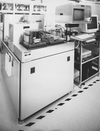
Since most photoresists are ultraviolet (UV) light sensitive, the processing area is lit with special yellow lights lacking sensitive UV wavelengths (see figure 1).
Figure 1. Photolithographic “Yellow room” equipment
Negative and positive UV resists are primarily in use in the industry. E-beam and x-ray resists, however, are gaining in market share because of their higher resolutions. Health concerns in lithography are primarily caused by potential reproductive hazards associated with selected positive resists (e.g., ethylene glycol monoethyl ether acetate as a carrier) that are currently being phased out by the industry. Occasional odours from the negative resists (e.g., xylene) also result in employee concerns. Because of these concerns, a great deal of time is spent by semiconductor industry industrial hygienists sampling photoresist operations. While this is useful in characterizing these operations, routine exposures during spinner and developer operations are typically less than 5% of the airborne standards for occupational exposure for the solvents used in the process (Scarpace et al. 1989).
A 1 hour exposure to ethylene glycol monoethyl ether acetate of 6.3 ppm was found during the operation of a spinner system. This exposure was primarily caused by poor work practices during the maintenance operation (Baldwin, Rubin and Horowitz 1993).
Drying and pre-baking
After the resist has been applied, the wafers are moved on a track or manually moved from the spinner to a temperature-controlled oven with a nitrogen atmosphere. A moderate temperature (70 to 90°C) causes the photoresist to cure (soft bake) and the remaining solvents to evaporate.
To ensure adhesion of the resist layer to the wafer, a primer, hexamethyldisilizane (HMDS), is applied to the wafer. The primer ties up molecular water on the surface of the wafer. HMDS is applied either directly in an immersion or spin-on process or through a vapour prime that offers process and cost advantages over the other methods.
Mask aligning and exposure
The mask and wafer are brought close together using a precise piece of optical/mechanical equipment, and the image on the mask is aligned to any pattern already existing in the wafer beneath the layer of photoresist. For the first mask, no alignment is necessary. In older technologies, alignment for successive layers is made possible by the use of a biscope (dual lens microscope) and precision controls for positioning the wafer with respect to the mask. In newer technologies alignment is done automatically using reference points on the wafers.
Once the alignment is done, a high-intensity ultraviolet mercury vapour or arc lamp source shines through the mask, exposing the resist in places not protected by opaque regions of the mask.
The various methods of wafer alignment and exposure include UV flood exposure (contact or proximity), UV exposure through projection lens for reduction (projection), UV step and repeat reduction exposure (projection), x-ray flood (proximity) and electron beam scan exposure (direct writing). The primary method in use involves UV exposure from mercury vapour and arc lamps through proximity or projection aligners. The UV resists are either designed to react to a broad spectrum of UV wavelengths, or they are formulated to react preferentially to one or more of the main spectrum lines emitted from the lamp (e.g., g-line at 435 nm, h-line at 405 nm and i-line at 365 nm).
The predominant wavelengths of UV light currently used in photomasking are 365 nm or above, but UV lamp spectra also contain significant energy in the wavelength region of health concern, the actinic region below 315 nm. Normally, the intensity of the UV radiation escaping from the equipment is less than both what is present from sunlight in the actinic region and the standards set for occupational exposure to UV.
Occasionally during maintenance, the alignment of the UV lamp requires that it be energized outside the equipment cabinet or without normal protective filters. Exposure levels during this operation can exceed occupational exposure limits, but standard cleanroom attire (e.g., smocks, vinyl gloves, face masks and polycarbonate safety glasses with UV inhibitor) is usually adequate to attenuate the UV light to below exposure limits (Baldwin and Stewart 1989).
While the predominant wavelengths for ultraviolet lamps used in photolithography are 365 nm or above, the quest for smaller features in advanced ICs is leading to the use of exposure sources with smaller wavelengths, such as deep UV and x rays. One new technology for this purpose is the use of krypton-fluoride excimer lasers used in steppers. These steppers use a wavelength of 248 nm with high laser power outputs. However, enclosures for these systems contain the beam during normal operation.
As with other equipment containing high-power laser systems used in semiconductor manufacturing, the main concern is when interlocks for the system must be defeated during beam alignment. High-powered lasers are also one of the most significant electrical hazards in the semiconductor industry. Even after power is off, a significant shock potential exists within the tool. Controls and safety design considerations for these systems are covered by Escher, Weathers and Labonville (1993).
One advanced-technology exposure source used in lithography is x rays. Emission levels from x-ray lithography sources may result in dose rates approaching 50 millisieverts (5 rems) per year in the centre of the equipment. Restricting access to areas inside the shielded wall is recommended to minimize exposure (Rooney and Leavey 1989).
Developing
During the development step the unpolymerized areas of the resist are dissolved and removed. Solvent-based developer is applied to the resist-covered wafer surface by either immersion, spraying or atomization. Developer solutions are identified in table 1. A solvent rinse (n-butyl acetate, isopropyl alcohol, acetone, etc.) is usually applied following the developer to remove any residual material. The resist remaining after developing protect the individual layers during subsequent processing.
Baking
After aligning, exposing and developing the resist, the wafers then move to another temperature-controlled oven with a nitrogen atmosphere. The higher-temperature oven (120 to 135°C) causes the photoresist to cure and fully polymerize on the wafer surface (hard bake).
Photoresist stripping
The developed wafer is then selectively etched using wet or dry chemicals (see “Etching” below). The remaining photoresist must be stripped from the wafer prior to further processing. This is done either by using wet chemical solutions in temperature-controlled baths or through the use of a plasma asher or dry chemical. Table 2 identifies both wet and dry chemical constituents. A discussion of dry chemical plasma etching—using the same equipment and principles of operation as plasma ashing—follows.
Table 2. Photoresist strippers
Wet chemical
Acid
Sulphuric (H2SO4) and chromic (CrO3)
Sulphuric (H2SO4) and ammonium persulphate ((NH4)2S2O8)
Sulphuric (H2SO4) and hydrogen peroxide (H2O2)
Organics
Phenols, sulphuric acids, trichlorobenzene, perchloroethylene
Glycol ethers, ethanolamine, triethanolamine
Sodium hydroxide and silicates (positive resist)
Dry chemical
Plasma ashing (stripping)
RF (radio frequency) power source—13.56 MHz or 2,450 MHz frequency
Oxygen (O2) source gas
Vacuum pump systems
—Oil lubricated with liquid nitrogen trap (old technology)
—Lubricated with inert perfluoropolyether fluids (newer technology)
—Dry pump (newest technology)
Etching
Etching removes layers of silicon dioxide (SiO2), metals and polysilicon, as well as resists, according to the desired patterns delineated by the resist. The two major categories of etching are wet and dry chemical. Wet etching is predominantly used and involves solutions containing the etchants (usually an acid mixture) at the desired strengths, which react with the materials to be removed. Dry etching involves the use of reactive gases under vacuum in a highly energized chamber, which also removes the desired layers not protected by resist.
Wet chemical
The wet chemical etching solutions are housed in temperature-controlled etch baths made of polypropylene (poly-pro), flame-resistant polypropylene (FRPP) or polyvinyl chloride (PVC). The baths generally are equipped with either ring-type plenum exhaust ventilation or slotted exhaust at the rear of the wet chemical etch station. Vertical laminar flow hoods supply uniformly filtered particulate-free air to the top surface of the etch baths. Common wet etchant chemical solutions are presented in table 3, in relation to the surface layer being etched.
Table 3. Wet chemical etchants
|
Material to etch |
Etchants |
|
|
Silicon |
||
|
Polycrystalline silicon (Si) |
Hydrofluoric, nitric, acetic acids and iodine |
|
|
Silicon dioxide (SiO2) |
Buffered oxide etch (BOE) - Hydrofluoric and |
|
|
Silicon nitride (Si3N4) |
Phosphoric and hydrofluoric acids |
|
|
CVD Oxide or Pad Etch |
Ammonium fluoride, acetic and hydrofluoric acids |
|
|
Metals |
||
|
Aluminium (Al) |
Phosphoric, nitric, acetic and hydrochloric acids |
|
|
Chromium-Nickel (Cr/Ni) |
Ceric ammonium nitrate and nitric acid |
|
|
Gold (Au) |
Hydrochloric and nitric acids (aqua regia) |
|
|
Silver (Ag) |
Ferric nitrate (FeNO3) and ethylene glycol |
|
|
Compound |
Formula |
Standard concentration (%) |
|
Acetic acid |
CH3COOH |
36 |
|
Ammonium fluoride |
NH4F |
40 |
|
Glacial acetic acid |
CH3COOH |
99.5 |
|
Hydrochloric acid |
HCl |
36 |
|
Hydrofluoric acid |
HF |
49 |
|
Nitric acid |
HNO3 |
67 |
|
Phosphoric acid |
H3PO4 |
85 |
|
Potassium hydroxide |
KOH |
50 or 10 |
|
Sodium hydroxide |
NaOH |
50 or 10 |
|
Sulphuric acid |
H2SO4 |
96 |
Vertically mounted flow supply hoods, when used in conjunction with splash shields and exhaust ventilation, can create areas of air turbulence within the wet chemical etch station. As a result, a decrease is possible in the effectiveness of the local exhaust ventilation in capturing and routing fugitive air contaminants from the etch baths in use.
The main concern with wet etching is the possibility of skin contact with the concentrated acids. While all the acids used in etching can cause acid burns, exposure to hydrofluoric acid (HF) is of particular concern. The lag time between skin contact and pain (up to 24 hours for solutions less than 20% HF and 1 to 8 hours for 20 to 50% solutions) can result in delayed treatment and more severe burns than expected (Hathaway et al. 1991).
Historically acid burns have been a particular problem within the industry. However, the incidence of skin contact with acids have been reduced in recent years. Some of this reduction was caused by product-related improvements in the etch process, such as the shift to dry etching, the use of more robotics and the installation of chemical dispense systems. The reduction in the rate of acid burns may also be attributed to better handling techniques, greater use of personal protective equipment, better designed wet decks and better training—all of which require continued attention if the rate is to decline further (Baldwin and Williams 1996).
Dry chemical
Dry chemical etching is an area of growing interest and usage due to its ability to better control the etching process and reduce contamination levels. Dry chemical processing effectively etches desired layers through the use of chemically reactive gases or through physical bombardment.
Chemically reactive plasma etching systems have been developed which can effectively etch silicon, silicon dioxide, silicon nitride, aluminium, tantalum, tantalum compounds, chromium, tungsten, gold and glass. Two kinds of plasma etching reactor systems are in use—the barrel, or cylindrical, and the parallel plate, or planar. Both operate on the same principles and primarily vary in configuration only.
A plasma is similar to a gas except that some of the atoms or molecules of the plasma are ionized and may contain a substantial number of free radicals. The typical reactor consists of a vacuum reactor chamber containing the wafer, usually made of aluminium, glass or quartz; a radio-frequency (RF) energy source—usually at 450 kHz, 13.56 MHz or 40.5 MHz and a control module to control processing time, composition of reactant gas, flow rate of gas and RF power level. In addition, an oil-lubricated (older technology) or dry (newer technology) roughing pump vacuum source is in line with the reactor chamber. Wafers are loaded into the reactor, either individually or in cassettes, a pump evacuates the chamber and the reagent gas (usually carbon tetrafluoride) is introduced. Ionization of the gas forms the etching plasma, which reacts with the wafers to form volatile products which are pumped away. The introduction of fresh reactant gas into the chamber maintains etching activity. Table 4 identifies the materials and plasma gases in use for etching various layers.
Table 4. Plasma etching gases and etched materials
|
Material |
Gas |
|
Silicon |
|
|
Polysilicon (polySi) and Silicon |
CF + O2, CCl4 or CF3Cl, CF4 and HCl |
|
Silicon dioxide (SiO2) |
C2F6, C3F8, CF4, SiF4, C5F12, CHF3, CCl2F2, SF6, HF |
|
Silicon nitride (Si3N4) |
CF4 + Ar, CF4 + O2, CF4 + H2 |
|
Metals |
|
|
Aluminium (Al) |
CCl4 or BCl3 + He or Ar |
|
Chromium (Cr) |
CCl4 |
|
Chromium oxide (CrO3) |
Cl2 + Ar or CCl4 + Ar |
|
Gallium arsenide (GaAs) |
CCl2F2 |
|
Vanadium (V) |
CF4 |
|
Titanium (Ti) |
CF4 |
|
Tantulum (Ta) |
CF4 |
|
Molybdenum (Mo) |
CF4 |
|
Tungsten (W) |
CF4 |
Another method that currently is being developed for etching is microwave downstream. It uses a high-power-density microwave discharge to produce metastable atoms with long lifetimes that etch material almost as if it were immersed in acid.
Physical etching processes are similar to sandblasting in that argon gas atoms are used to physically bombard the layer to be etched. A vacuum pump system is used to remove dislocated material. Reactive ion etching involves a combination of chemical and physical dry etching.
The sputtering process is one of ion impact and energy transfer. Sputter etching incorporates a sputtering system, where the wafer to be etched is attached to a negative electrode or target in a glow-discharge circuit. Material sputters from the wafer by bombardment with positive ions, usually argon, and results in the dislocation of the surface atoms. Power is provided by an RF source at 450 kHz frequency. An in-line vacuum system is used for pressure control and reactant removal.
Ion-beam etching and milling is a gentle etching process which uses a beam of low-energy ions. The ion-beam system consists of a source to generate the ion beam, a work chamber in which the etching or milling occurs, fixturing with a target plate for holding the wafers in the ion beam, a vacuum pump system, supporting electronics and instruments. The ion beam is extracted from an ionized gas (argon or argon/oxygen) or plasma, which is created by the electrical discharge. The discharge is obtained by applying a voltage between an electron-emitting hot-filament cathode and an anode cylinder located in the outer diameter of the discharge region.
Ion-beam milling is done in the low-energy range of ion bombardment, where only surface interactions occur. These ions, usually in the 500 to 1,000 eV range, strike a target and sputter off surface atoms by breaking the forces bonding the atom to its neighbour. Ion-beam etching is done in a slightly higher energy range, which involves a more dramatic dislocation of surface atoms.
Reactive ion etching (RIE) is a combination of physical sputtering and chemical reactive species etching at low pressures. RIE uses ion bombardment to achieve directional etching and also a chemically reactive gas, carbon tetrafluoride (CF4) or carbon tetrachloride (CCl4), to maintain good etched layer selectivity. A wafer is placed in a chamber with an atmosphere of chemically reactive gas compound at a low pressure of about 0.1 torr (1.3 x 10⁻⁴ atmosphere). An electrical discharge creates a plasma of reactive “free radicals” (ions) with an energy of a few hundred electron volts. The ions strike the wafer surface vertically, where they react to form volatile species that are removed by a low-pressure in-line vacuum system.
Dry etchers sometimes have a cleaning cycle that is used to remove deposits that accumulate on the inside of the reaction chambers. Parent compounds used for the cleaning cycle plasmas include nitrogen trifluoride (NF3), hexafluoroethane (C2F6) and octafluoropropane (C3F8).
These three gases used in the cleaning process, and many of the gases used in etching, are a cornerstone to an environmental issue facing the semiconductor industry which surfaced in the mid-1990s. Several of the highly fluorinated gases were identified as having significant global warming (or greenhouse effect) potential. (These gases are also referred to as PFCs, perfluorinated compounds.) The long atmospheric lifetime, high global warming potential and significant increased usage of PFCs like NF3, C2F6, C3F8, CF4, trifluoromethane (CHF3) and sulphur hexafluoride (SF6) had the semiconductor industry focus on ways to reduce their emissions.
Atmospheric emissions of PFCs from the semiconductor industry have been due to poor tool efficiency (many tools consumed only 10 to 40% of the gas used) and inadequate air emission abatement equipment. Wet scrubbers are not effective in removing PFCs, and tests on many combustion units found poor destruction efficiencies for some gases, especially CF4. Many of these combustion units broke down C2F6 and C3F8 into CF4. Also, the high cost of ownership for these abatement tools, their power demand, their release of other global warming gases and their combustion by-products of hazardous air pollutants indicated combustion abatement was not a suitable method for controlling PFC emissions.
Making process tools more efficient, identifying and developing more environmentally friendly alternatives to these dry etchant gases and recovery/recycling of the exhaust gases have been the environmental emphases associated with dry etchers.
The major occupational hygiene emphasis for dry etchers has been on potential exposures to maintenance personnel working on the reaction chambers, pumps and other associated equipment that may contain reaction product residues. The complexity of plasma metal etchers and the difficulty in characterizing the odours associated with their maintenance has made them the subject of many investigations.
The reaction products formed in plasma metal etchers are a complex mixture of chlorinated and fluorinated compounds. The maintenance of metal etchers often involves short-duration operations that generate strong odours. Hexachloroethane was found to be the major cause of odour in one type of aluminium etcher (Helb et al. 1983). In another, cyanogen chloride was the main problem: exposure levels were 11 times the 0.3 ppm occupational exposure limit (Baldwin 1985). In still other types of etchers, hydrogen chloride is associated with the odour; maximum exposure measured was 68 ppm (Baldwin, Rubin and Horowitz 1993). For additional information on the subject see Mueller and Kunesh (1989).
The complexity of the chemistries present in metal etcher exhausts has led researchers to develop experimental methods for investigating the toxicity of these mixtures (Bauer et al. 1992a). Application of these methods in rodent studies indicates certain of these chemical mixtures are suspected mutagens (Bauer et al. 1992b) and suspected reproductive toxins (Schmidt et al. 1995).
Because dry etchers operate as closed systems, chemical exposure to the operators of the equipment typically does not occur while the system is closed. One rare exception to this is when the purge cycle for older batch etchers is not long enough to adequately remove the etchant gases. Brief but irritating exposures to fluorine compounds that are below the detection limit for typical industrial hygiene monitoring procedures have been reported when the doors to these etchers are opened. Normally this can be corrected by simply increasing the length of the purge cycle prior to opening the etch chamber door.
The primary concern for operator exposure to RF energy comes during plasma etching and ashing (Cohen 1986; Jones 1988). Typically, the leakage of RF energy can be caused by:
- misaligned doors
- cracks and holes in the cabinets
- metal tables and electrical cables acting as antennae due to improper grounding of the etcher
- no attenuating screen in the viewing window of the etcher (Jones 1988; Horowitz 1992).
RF exposure can also occur during the maintenance of etchers, particularly if the equipment cabinet has been removed. An exposure of 12.9 mW/cm2 was found at the top of an older model plasma etcher with the cover removed for maintenance (Horowitz 1992). The actual RF radiation leakage in the area where the operator stands was typically less than 4.9 mW/cm2.
Doping
The formation of an electrical junction or boundary between p and n regions in a single crystal silicon wafer is the essential element for the functioning of all semiconductor devices. Junctions permit current to flow in one direction much more easily than in the other. They provide the basis for diode and transistor effects in all semiconductors. In an integrated circuit, a controlled number of elemental impurities or dopants, must be introduced into selected etched regions of the silicon substrate, or wafer. This can be done either by diffusion or ion implantation techniques. Regardless of the technique used, the same types or dopants are used for the production of semiconductor junctions. Table 5 identifies the main components used for doping, their physical state, electrical type (p or n) and the primary junction technique in use—diffusion or ion implantation.
Table 5. Junction formation dopants for diffusion and ion implantation
|
Element |
Compound |
Formula |
State |
Technique |
|
n-type |
||||
|
Antimony |
Antimony trioxide |
Sb2O3 |
Solid |
Diffusion |
|
Arsenic |
Arsenic trioxide |
As2O3 |
Solid |
Diffusion |
|
Phosphorus |
Phosphorus pentoxide |
P2O5 |
Solid |
Diffusion |
|
p-type |
||||
|
Boron |
Boron nitride |
BN |
Solid |
Diffusion |
Routine chemical exposures to operators of both diffusion furnaces and ion implanters are low—typically less that the detection limit of standard occupational hygiene sampling procedures. Chemical concerns with the process centre on the possibility of toxic gas releases.
As early as the 1970s, progressive semiconductor manufacturers began installing the first continuous gas-monitoring systems for flammable and toxic gases. The main focus of this monitoring was to detect accidental releases of the most toxic dopant gases with odour thresholds above their occupational exposure limits (e.g., arsine and diborane).
Most industrial hygiene air monitors in the semiconductor industry are used for flammable and toxic gas leak detection. However, some facilities are also using continuous monitoring systems to:
- analyse exhaust duct (stack) emissions
- quantify ambient air concentrations of volatile chemicals
- identify and quantify odours in the fab areas.
The technologies most used in the semiconductor industry for this type of monitoring are colorimetric gas detection (e.g., MDA continuous gas detector), electrochemical sensors (e.g., sensydyne monitors) and Fourier transform infrared (e.g., Telos ACM) (Baldwin and Williams 1996).
Diffusion
Diffusion is a term used to describe the movement of dopants away from regions of high concentration at the source end of the diffusion furnace to regions of lower concentration within the silicon wafer. Diffusion is the most established method of junction formation.
This technique involves subjecting a wafer to a heated atmosphere within the diffusion furnace. The furnace contains the desired dopants in a vapour form and results in creating regions of doped electrical activity, either p or n. The most commonly used dopants are boron for p-type; and phosphorus (P), arsenic (As) or antimony (Sb) for n-type (see table 5).
Typically, wafers are stacked in a quartz carrier or boat and placed in the diffusion furnace. The diffusion furnace contains a long quartz tube and a mechanism for accurate temperature control. Temperature control is extremely important, as the rates of diffusion of the various silicon dopants are primarily a function of temperature. The temperatures in use range from 900 to 1,300 oC, depending on the specific dopant and process.
The heating of the silicon wafer to a high temperature allows the impurity atoms to diffuse slowly through the crystal structure. Impurities move more slowly through silicon dioxide than through the silicon itself, enabling the thin oxide pattern to serve as a mask and thereby permitting the dopant to enter silicon only where it is unprotected. After enough impurities have accumulated, the wafers are removed from the furnace and diffusion effectively ceases.
For maximum control, most diffusions are performed in two steps—predeposition and drive in. The predeposit, or diffusion with constant source, is the first step and takes place in a furnace in which the temperature is selected to achieve the best control of impurity amounts. The temperature determines the solubility of the dopant. After a comparatively short predeposit treatment, the wafer is physically moved to a second furnace, usually at a higher temperature, where a second heat treatment drives in the dopant to the desired depth of diffusion in the silicon wafer lattice.
The dopant sources used in the predeposit step are in three distinct chemical states: gas, liquid and solid. Table 5 identifies the various types of diffusion source dopants and their physical states.
Gases are generally supplied from compressed gas cylinders with pressure controls or regulators, shut-off valves and various purging attachments and are dispensed through small-diameter metal tubing.
Liquids are dispensed normally from bubblers, which saturate a carrier gas stream, usually nitrogen, with the liquid dopant vapours, as is described in the section on wet oxidation. Another form of liquid dispensing is through the use of the spin-on dopant apparatus. This entails putting a solid dopant in solution with a liquid solvent carrier, then dripping the solution on the wafer and spinning, in a manner similar to the application of photoresists.
Solid sources may be in the shape of a boron nitride wafer, which is sandwiched between two silicon wafers to be doped and then placed in a diffusion furnace. Also, the solid dopants, in powder or bead form, may be placed in a quartz bomb enclosure (arsenic trioxide), manually dumped in the source end of a diffusion tube or loaded in a separate source furnace in line with the main diffusion furnace.
In the absence of proper controls, arsenic exposures above 0.01 mg/m3 were reported during the cleaning of a deposition furnace (Wade et al. 1981) and during the cleaning of source housing chambers for solid-source ion implanters (McCarthy 1985; Baldwin, King and Scarpace 1988). These exposures occurred when no precautions were taken to limit the amount of dust in the air. However, when residues were kept wet during cleaning, exposures were reduced to far below the airborne exposure limit.
In the older diffusion technologies safety hazards exist during the removal, cleaning and installation of furnace tubes. The hazards include potential cuts from broken quartz ware and acid burns during the manual cleaning. In newer technologies these hazards are lessened by in situ tube cleaning that eliminates much of the manual handling.
Diffusion furnace operators experience the highest routine cleanroom exposure to extremely low-frequency electromagnetic fields (e.g., 50 to 60 hertz) in semiconductor manufacturing. Average exposures greater than 0.5 microteslas (5 milligauss) were reported during actual operation of the furnaces (Crawford et al. 1993). This study also noted that cleanroom personnel working in the vicinity of diffusion furnaces had average measured exposures that were noticeably higher than those of other cleanroom workers. This finding was consistent with point measurements reported by Rosenthal and Abdollahzadeh (1991), who found that diffusion furnaces produced proximity readings (5 cm or 2 inches away) as high as 10 to 15 microteslas, with the surrounding fields falling off more gradually with distance than other cleanroom equipment studied; even at 6 feet away from diffusion furnaces, the reported flux densities were 1.2 to 2 microteslas (Crawford et al. 1993). These emission levels are well below current health-based exposure limits set by the World Health Organization and those set by individual countries.
Ion implantation
Ion implantation is the newer method of introducing impurities elements at room temperature into silicon wafers for junction formation. Ionized dopant atoms (i.e., atoms stripped of one or more of their electrons) are accelerated to a high energy by passing them through a potential difference of tens of thousands of volts. At the end of their path, they strike the wafer and are embedded at various depths, depending on their mass and energy. As in conventional diffusion, a patterned oxide layer or a photoresist pattern selectively masks the wafer from the ions.
A typical ion implantation system consists of an ion source (gaseous dopant source, usually in small lecture bottles), analysis equipment, accelerator, focusing lens, neutral beam trap, scanner process chamber and a vacuum system (normally three separate sets of in-line roughing and oil-diffusion pumps). The stream of electrons is generated from a hot filament by resistance, an arc discharge or cold cathode electron beam.
Generally, after wafers are implanted, a high temperature annealing step (900 to 1,000°C) is performed by a laser beam anneal or pulsed annealing with an electron-beam source. The annealing process helps repair the damage to the exterior surface of the implanted wafer caused by the bombardment of dopant ions.
With the advent of a safe delivery system for arsine, phosphine and boron trifluoride gas cylinders used in ion implanters, the potential for catastrophic release of these gases has been greatly reduced. These small gas cylinders are filled with a compound to which the arsine, phosphine and boron trifluoride are adsorbed. The gases are pulled out of the cylinders by use of a vacuum.
Ion implanters are one of the most significant electrical hazards in the semiconductor industry. Even after power is off, a significant shock potential exists within the tool and must be dissipated prior to working inside the implanter. A careful review of maintenance operations and the electrical hazards is warranted for all newly installed equipment, but especially for ion implanters.
Exposures to hydrides (probably a mixture of arsine and phosphine) as high as 60 ppb have been found during ion implanter cryo-pump maintenance (Baldwin, Rubin and Horowitz 1993). Also, high concentrations of both arsine and phosphine can off-gas from contaminated implanter parts that are removed during preventive maintenance (Flipp, Hunsaker and Herring 1992).
Portable vacuum cleaners with high-efficiency particulate attenuator (HEPA) filters are used to clean arsenic-contaminated work surfaces in ion implantation areas. Exposures above 1,000 μg/m3 were measured when HEPA vacuums were improperly cleaned. HEPA vacuums, when discharging to the workspace, can also efficiently distribute the distinctive, hydride-like odour associated with ion implanter beam line cleaning (Baldwin, Rubin and Horowitz 1993).
While a concern, there have been no published reports of significant dopant gas exposures during oil changes of vacuum pumps used with dopants—possibly because this is usually done as a closed system. The lack of reported exposure may also be a result of low levels of off-gassing of hydrides from the used oil.
The result of a field study where 700 ml of used roughing pump oil from an ion implanter which used both arsine and phosphine was heated only showed detectable concentrations of airborne hydrides in the pump head space when the pump oil exceeded 70oC (Baldwin, King and Scarpace 1988). Since normal operating temperatures for mechanical roughing pumps are 60 to 80oC, this study did not indicate the potential for a significant exposure.
During ion implantation, x rays are formed incidental to the operation. Most implanters are designed with sufficient cabinet shielding (which includes lead sheeting strategically placed around the ion source housing and adjacent access doors) to maintain employee exposure below 2.5 microsieverts (0.25 millirems) per hour (Maletskos and Hanley 1983). However, an older model of implanters was found to have x-ray leakage above 20 microsieverts per hour (μSv/hr) at the unit’s surface (Baldwin, King and Scarpace 1988). These levels were reduced to less than 2.5 μSv/hr after additional lead shielding was installed. Another older model of ion implanter was found to have x-ray leakage around an access door (up to 15 μSv/hr) and at a viewport (up to 3 μSv/hr). Additional lead shielding was added to attenuate possible exposures (Baldwin, Rubin and Horowitz 1993).
In addition to x-ray exposures from ion implanters, the possibility of neutron formation has been postulated if the implanter is operated above 8 million electron volts (MeV) or deuterium gas is used as an ion source (Rogers 1994). However, typically implanters are designed to operate at well below 8 MeV, and deuterium is not commonly used in the industry (Baldwin and Williams 1996).
Chemical vapour deposition
Chemical vapour deposition (CVD) involves the layering of additional material on the silicon wafer surface. CVD units normally operate as a closed system resulting in little or no chemical exposure to the operators. However, brief hydrogen chloride exposure above 5 ppm can occur when certain CVD prescrubbers are cleaned (Baldwin and Stewart 1989). Two broad categories of deposition are in common use—epitaxial and the more general category of non-epitaxial CVD.
Epitaxial chemical vapour deposition
Epitaxial growth is rigidly controlled deposition of a thin single crystal film of a material which maintains the same crystal structure as the existing substrate wafer layer. It serves as a matrix for fabricating semiconductor components in subsequent diffusion processes. Most epitaxial films are grown on substrates of the same material, such as silicon on silicon, in a process referred to as homoepitaxy. Growing layers of different materials on a substrate, such as silicon on sapphire, is called heteroepitaxy IC device processing.
Three primary techniques are used to grow epitaxial layers: vapour phase, liquid phase and molecular beam. Liquid-phase and molecular-beam epitaxy are primarily used in the processing of III-V (e.g., GaAs) devices. These are discussed in the article “III-V semiconductor manufacturing”.
Vapour-phase epitaxy is used to grow a film by the CVD of molecules at a temperature of 900 to 1,300oC. Vapours containing the silicon and controlled amounts of p- or n-type dopants in a carrier gas (usually hydrogen) are passed over heated wafers to deposit doped layers of silicon. The process is generally performed at atmospheric pressure.
Table 6 identifies the four major types of vapour-phase epitaxy, parameters and the chemical reactions taking place.
Table 6. Major categories of silicon vapour-phase epitaxy
|
Parameters |
||
|
Pressure |
Atmospheric |
|
|
Temperature |
900–1300 °C |
|
|
Silicon sources |
Silane (SiH4), silicon tetrachloride (SiCl4), trichlorosilane (SiHCl3), |
|
|
Dopant gases |
Arsine (AsH3), phosphine (PH3), diborane (B2H6) |
|
|
Dopant gas concentration |
≈100 ppm |
|
|
Etchant gas |
Hydrogen chloride (HCl) |
|
|
Etchant gas concentration |
≈1–4% |
|
|
Carrier gases |
Hydrogen (H2), nitrogen (N2) |
|
|
Heating source |
Radio frequency (RF) or infrared (IR) |
|
|
Vapour-phase epitaxy types |
Chemical reactions |
|
|
Hydrogen reduction of silicon tetrachloride |
SiCl4 + 2H2 → Si + 4HCl |
|
|
Pyrolytic decomposition of silane |
SiH4 → Si + 2H2 |
|
|
Hydrogen reduction of trichlorosilane |
SiHCl3 + H2 → Si + 3HCl |
|
|
Reduction of dichlorosilane |
SiH2Cl2 → Si + 2HCl |
|
The deposition sequence normally followed in an epitaxial process involves:
- substrate cleaning—physical scrubbing, solvent degreasing, acid cleaning (sulphuric, nitric and hydrochloric, and hydrofluoric is a common sequence) and drying operation
- wafer loading
- heat up—nitrogen purging and heating to approximately 500 °C, then hydrogen gas is used and RF generators inductively heat wafers
- hydrogen chloride (HCl) etch—usually 1 to 4% concentration of HCl is dispensed to the reactor chamber
- deposition—silicon source and dopant gases are metered in and deposited on wafer surface
- cool down—hydrogen gas switched to nitrogen again at 500°C
- unloading.
Non-epitaxial chemical vapour deposition
Whereas epitaxial growth is a highly specific form of CVD where the deposited layer has the same crystalline structure orientation as the substrate layer, non-epitaxial CVD is the formation of a stable compound on a heated substrate by the thermal reaction or decomposition of gaseous compounds.
CVD can be used to deposit many materials, but in silicon semiconductor processing the materials generally encountered, in addition to epitaxial silicon, are:
- polycrystalline silicon (poly Si)
- silicon dioxide (SiO2—both doped and undoped; p-doped glass)
- silicon nitride (Si3N4).
Each of these materials may be deposited in a variety of ways, and each has many applications.
Table 7 identifies the three major categories of CVD using operating temperature as a mechanism of differentiation.
Table 7. Major categories of silicon chemical vapour deposition (CVD)
|
Parameters |
||||
|
Pressure |
Atmospheric (APCVD) or low pressure (LPCVD) |
|||
|
Temperature |
500–1,100 °C |
|||
|
Silicon and nitride sources |
Silane (SiH4), silicon tetrachloride (SiCl4), ammonia (NH3), nitrous oxide (N20) |
|||
|
Dopant sources |
Arsine (AsH3), phosphine (PH3), diborane (B2H6) |
|||
|
Carrier gases |
Nitrogen (N2), hydrogen (H2) |
|||
|
Heating source |
Cold wall system—radio frequency (RF) or infrared (IR) |
|||
|
CVD type |
Reaction |
Carrier gas |
Temperature |
|
|
Medium temperature (≈ 600–1,100 °C) |
||||
|
Silicon nitride (Si3N4) |
3SiH4 + 4 NH3 → Si3N4 + 12H2 |
H2 |
900–1,100 °C |
|
|
Polysilicon (poly Si) |
SiH4 + Heat → Si + 2H2 |
H2 |
850–1,000 °C |
|
|
Silicon dioxide (SiO2) |
SiH4 + 4CO2 → SiO2 + 4CO + 2H2O |
N2 |
500–900 °C |
|
|
Low temperature (≈<600 C) Silox, Pyrox, Vapox and Nitrox** |
||||
|
Silicon dioxide (SiO2) or p-doped SiO2 |
||||
|
Silox |
SiH4 + 2O2 + Dopant → SiO2 + 2H2O |
N2 |
200–500 °C |
|
|
Pyrox |
SiH4 + 2O2 + Dopant → SiO2 + 2H2O |
N2 |
<600 °C |
|
|
Vapox |
SiH4 + 2O2 + Dopant → SiO2 + 2H2O |
N2 |
<600 °C |
|
|
Silicon nitride (Si3N4) |
||||
|
Nitrox |
3SiH4 + 4NH3 (or N2O*) → Si3N4 + 12H2 |
N2 |
600–700 °C |
|
|
Low temperature plasma enhanced (passivation) (<600°C) |
||||
|
Utilizing radio-frequency (RF) or |
||||
|
Silicon dioxide (SiO2) |
SiH4 + 2O2 → SiO2 + 2H20 |
|||
|
Silicon nitride (Si3N4) |
3SiH4 + 4NH3 (or N2O*) → Si3N4 + 12H2 |
|||
* Note: Reactions are not stoichiometrically balanced.
**Generic, proprietary or trademark names for CVD reactor systems
The following components are found in nearly all the types of CVD equipment:
- reaction chamber
- gas control section
- time and sequence control
- heat source for substrates
- effluent handling.
Basically, the CVD process entails supplying controlled amounts of silicon or nitride source gases, in conjunction with nitrogen and/or hydrogen carrier gases, and a dopant gas if desired, for chemical reaction within the reactor chamber. Heat is applied to provide the necessary energy for the chemical reaction in addition to controlling the surface temperatures of the reactor and wafers. After the reaction is complete, the unreacted source gas plus the carrier gas are exhausted through the effluent handling system and vented to the atmosphere.
Passivation is a functional type of CVD. It involves the growth of a protective oxide layer on the surface of the silicon wafer, generally as the last fabrication step prior to non-fabrication processing. The layer provides electrical stability by isolating the integrated circuit’s surface from electrical and chemical conditions in the environment.
Metallization
After the devices have been fabricated in the silicon substrate, they must be connected together to perform circuit functions. This process is known as metallization. Metallization provides a means of wiring or interconnecting the uppermost layers of integrated circuits by depositing complex patterns of conductive materials, which route electrical energy within the circuits.
The broad process of metallization is differentiated according to the size and thickness of the layers of metals and other materials being deposited. These are:
- thin film—approximate film thickness of one micron or less
- thick film—approximate film thickness of 10 microns or greater
- plating—film thicknesses are variable from thin to thick, but generally thick films.
The most common metals used for silicon semiconductor metallization are: aluminium, nickel, chromium or an alloy called nichrome, gold, germanium, copper, silver, titanium, tungsten, platinum and tantalum.
Thin or thick films may also be evaporated or deposited on various ceramic or glass substrates. Some examples of these substrates are: alumina (96% Al203), beryllia (99% BeO), borosilicate glass, pyroceram and quartz (SiO2).
Thin film
Thin film metallization is often applied through the use of a high-vacuum or partial-vacuum deposition or evaporation technique. The major types of high-vacuum evaporation are electron beam, flash and resistive, while partial-vacuum deposition is primarily done by sputtering.
To perform any type of thin film vacuum metallization, a system usually consists of the following basic components:
- a chamber that can be evacuated to provide a sufficient vacuum for deposition
- a vacuum pump (or pumps) to reduce ambient gases in the chamber
- instrumentation for monitoring the vacuum level and other parameters
- a method of depositing or evaporating the layers of metallizing material.
Electron-beam evaporation, frequently called E beam, uses a focused beamof electrons to heat the metallization material. A high-intensity beam of electrons is generated in a manner similar to that used in a television picture tube. A stream of electrons is accelerated through an electrical field of typically 5 to 10 kV and focused on the material to be evaporated. The focused beam of electrons melts the material contained in a water-cooled block with a large depression called a hearth. The melted material then vaporizes within the vacuum chamber and condenses on the cool wafers as well as on the entire chamber surface. Then standard photoresist, exposure, development and wet or dry etch operations are performed to delineate the intricate metallized circuitry.
Flash evaporation is another technique for the deposition of thin metallized films. This method is primarily used when a mixture of two materials (alloys) are to be simultaneously evaporated. Some examples of two component films are: nickel/chromium (Nichrome), chromium/silicon monoxide (SiO) and aluminium/silicon.
In flash evaporation, a ceramic bar is heated by thermal resistance and a continuously fed spool of wire, stream of pellets or vibrationally dispensed powder is brought in contact with the hot filament or bar. The vaporized metals then coat the interior chamber and wafer surfaces.
Resistive evaporation (also known as filament evaporation) is the simplest and least expensive form of deposition. The evaporation is accomplished by gradually increasing the current flowing through the filament to first melt the loops of material to be evaporated, thereby wetting the filament. Once the filament is wetted, the current through the filament is increased until evaporation occurs. The primary advantage of resistive evaporation is the wide variety of materials that can be evaporated.
Maintenance work is sometimes done on the inside surface of E-beam evaporator deposition chambers called bell jars. When the maintenance technicians have their heads inside the bell jars, significant exposures can occur. Removing the metal residues that deposit on the inside surface of bell jars may result in such exposures. For example, technician exposures far above the airborne exposure limit for silver were measured during residue removal from an evaporator used to deposit silver (Baldwin and Stewart 1989).
Cleaning bell jar residues with organic cleaning solvents can also result in high solvent exposure. Technician exposures to methanol above 250 ppm have occurred during this type of cleaning. This exposure can be eliminated by using water as the cleaning solvent instead of methanol (Baldwin and Stewart 1989).
The sputtering deposition process takes place in a low-pressure or partial-vacuum gas atmosphere, using either direct electric current (DC, or cathode sputtering) or RF voltages as a high-energy source. In sputtering, ions of argon inert gas are introduced into a vacuum chamber after a satisfactory vacuum level has been reached through the use of a roughing pump. An electric field is formed by applying a high voltage, typically 5,000 V, between two oppositely charged plates. This high-energy discharge ionizes the argon gas atoms and causes them to move and accelerate to one of the plates in the chamber called the target. When the argon ions strike the target made of the material to be deposited, they dislodge, or sputter, these atoms or molecules. The dislodged atoms of the metallization material are then deposited in a thin film on the silicon substrates which face the target.
RF leakage from the sides and backs on many older sputter units was found to exceed the occupational exposure limit (Baldwin and Stewart 1989). Most of the leakage was attributable to cracks in the cabinets caused by repeated removal of the maintenance panels. In newer models by the same manufacturer, panels with wire mesh along the seams prevent significant leakage. The older sputterers can be retrofitted with wire mesh or, alternatively, copper tape can be used to cover the seams to reduce the leakage.
Thick film
The structure and dimension of most thick films are not compatible with the metallization of silicon integrated circuits, primarily due to size constraints. Thick films are used mostly for metallization of hybrid electronic structures, such as in the manufacture of LCDs.
The silk-screening process is the dominant method of thick film application. Thick film materials typically used are palladium, silver, titanium dioxide and glass, gold-platinum and glass, gold-glass and silver-glass.
Resistive thick films are normally deposited and patterned on a ceramic substrate using silk-screening techniques. Cermet is a form of resistive thick film composed of a suspension of conductive metal particles in a ceramic matrix with an organic resin as filler. Typical cermet structures are composed of chromium, silver or lead oxide in a silicon monoxide or dioxide matrix.
Plating
Two basic types of plating techniques are used in forming metallic films on semiconductor substrates: electroplating and electroless plating.
In electroplating, the substrate to be plated is placed at the cathode, or negatively charged terminal, of the plating tank and immersed in an electrolytic solution. An electrode made of the metal to be plated serves as the anode, or positively charged terminal. When a direct current is passed through the solution, the positively charged metal ions, which dissolve into the solution from the anode, migrate and plate on the cathode (substrate). This method of plating is used for forming conductive films of gold or copper.
In electroless plating, the simultaneous reduction and oxidation of the metal to be plated is used in forming a free metal atom or molecule. Since this method does not require electrical conduction during the plating process, it can be used with insulating-type substrates. Nickel, copper and gold are the most common metals deposited in this manner.
Alloying/annealing
After the metallized interconnections have been deposited and etched, a final step of alloying and annealing may be performed. The alloying consists of placing the metallized substrates, usually with aluminium, in a low-temperature diffusion furnace to assure a low-resistance contact between the aluminium metal and silicon substrate. Finally, either during the alloy step or directly following it, the wafers are often exposed to a gas mixture containing hydrogen in a diffusion furnace at 400 to 500°C. The annealing step is designed to optimize and stabilize the characteristics of the device by combining the hydrogen with uncommitted atoms at or near the silicon-silicon dioxide interface.
Backlapping and backside metallization
There is also an optional metallization processing step called backlapping. The backside of the wafer may be lapped or ground down using a wet abrasive solution and pressure. A metal such as gold may be deposited on the back side of the wafer by sputtering. This makes attachment of the separated die to the package easier in the final assembly.
Assembly and testing
Non-fabrication processing, which includes external packaging, attachments, encapsulation, assembly and testing, is normally performed in separate production facilities and many times is done in Southeast Asian countries, where these labour-intensive jobs are less expensive to perform. In addition, ventilation requirements for process and particulate control are generally different (non-cleanroom) in the non-fabrication processing areas. These final steps in the manufacturing process involve operations that include soldering, degreasing, testing with chemicals and radiation sources, and trimming and marking with lasers.
Soldering during semiconductor manufacturing normally does not result in high lead exposures. To prevent thermal damage to the integrated circuit, the solder temperature is kept below the temperature where significant molten lead fume formation can occur (430°C). However, cleaning solder equipment by scraping or brushing of the lead-containing residues can result in lead exposures above 50 μg/m3 (Baldwin and Stewart 1989). Also, lead exposures of 200 μg/m3 have occurred when improper dross removal techniques are used during wave solder operations (Baldwin and Williams 1996).
One growing concern with solder operations is respiratory irritation and asthma due to exposure to the pyrolysis products of the solder fluxes, particularly during hand soldering or touch-up operations, where historically local exhaust ventilation has not been commonly used (unlike wave solder operations, which for the last few decades have typically been enclosed in exhausted cabinets) (Goh and Ng 1987). See the article “Printed circuit board and computer assembly” for more details.
Since colophony in the solder flux is a sensitizer, all exposures should be reduced to as low as possible, regardless of air sampling results. New soldering installations particularly should include local exhaust ventilation when soldering is to be performed for extended periods of time (e.g., greater than 2 hours).
Fumes from hand soldering will rise vertically on thermal currents, entering the employee’s breathing zone as the person leans over the point of soldering. Control usually is achieved by means of effective high velocity and low volume local exhaust ventilation at the solder tip.
Devices that return filtered air to the workplace may, if the filtration efficiency is inadequate, cause secondary pollution which can affect people in the workroom other than those soldering. Filtered air should not be returned to the workroom unless the amount of soldering is small and the room has good general dilution ventilation.
Wafer sort and test
After wafer fabrication is completed, each intrinsically finished wafer undergoes a wafer sort process where integrated circuitry on each specific die is electrically tested with computer-controlled probes. An individual wafer may contain from one hundred to many hundreds of separate dies or chips which must be tested. After the test results are finished, the dies are physically marked with an automatically dispensed one-component epoxy resin. Red and blue are used to identify and sort dies which do not meet the desired electrical specifications.
Die separation
With the devices or circuits on the wafer tested, marked and sorted, the individual dies on the wafer must be physically separated. A number of methods have been designed for separating the individual dies—diamond scribing, laser scribing and diamond wheel sawing.
Diamond scribing is the oldest method in use and involves drawing a precisely shaped diamond-imbedded tip across the wafer along the scribe line or “street” separating the individual dies on the wafer surface. The imperfection in the crystal structure caused by scribing allows the wafer to be bent and fractured along this line.
Laser scribing is a relatively recent die separation technique. A laser beam is generated by a pulsed, high-powered neodymium-yttrium laser. The beam generates a groove in the silicon wafer along the scribe lines. The groove serves as the line along which the wafer breaks.
A widely used method of die separation is wet sawing—cutting substrates along the street with a high-speed circular diamond saw. Sawing can either partially cut (scribe) or completely cut (dice) through the silicon substrate. A wet slurry of material removed from the street is generated by sawing.
Die attach and bonding
The individual die or chip must be attached to a carrier package and metal lead-frame. Carriers are typically made of an insulating material, either ceramic or plastic. Ceramic carrier materials are usually made of alumina (Al2O3), but can possibly consist of beryllia (BeO) or steatite (MgO-SiO2). Plastic carrier materials are either of the thermoplastic or thermosetting resin type.
The attachment of the individual die is generally accomplished by one of three distinct types of attachment: eutectic, preform and epoxy. Eutectic die attachment involves using an eutectic brazing alloy, such as gold-silicon. In this method, a layer of gold metal is predeposited on the backside of the die. By heating the package above the eutectic temperature (370°C for gold-silicon) and placing the die on it, a bond is formed between the die and package.
Preform bonding involves the use of a small piece of special composition material that will adhere to both the die and the package. A preform is placed on the die-attach area of a package and allowed to melt. The die is then scrubbed across the region until the die is attached, and then the package is cooled.
Epoxy bonding involves the use of an epoxy glue to attach the die to the package. A drop of epoxy is dispensed on the package and the die placed on top of it. The package may need to be baked at an elevated temperature to cure the epoxy properly.
Once the die is physically attached to the package, electrical connections must be provided between the integrated circuit and package leads. This is accomplished by using either thermocompression, ultrasonic or thermosonic bonding techniques to attach gold or aluminium wires between the contact areas on the silicon chip and the package leads.
Thermocompression bonding is often used with gold wire and involves heating the package to approximately 300oC and forming the bond between the wire and bonding pads using both heat and pressure. Two major types of thermocompression bonding are in use—ball bonding and wedge bonding. Ball bonding, which is used only with gold wire, feeds the wire through a capillary tube, compresses it, and then a hydrogen flame melts the wire. In addition, this forms a new ball on the end of the wire for the next bonding cycle. Wedge bonding involves a wedge-shaped bonding tool and a microscope used for positioning the silicon chip and package accurately over the bonding pad. The process is performed in an inert atmosphere.
Ultrasonic bonding uses a pulse of ultrasonic, high-frequency energy to provide a scrubbing action that forms a bond between the wire and the bonding pad. Ultrasonic bonding is primarily used with aluminium wire and is often preferred to thermocompression bonding, since it does not require the circuit chip to be heated during the bonding operation.
Thermosonic bonding is a recent technological change in gold wire bonding. It involves the use of a combination of ultrasonic and heat energies and requires less heat than thermocompression bonding.
Encapsulation
The primary purpose of encapsulation is to put an integrated circuit into a package which meets the electrical, thermal, chemical and physical requirements associated with the application of the integrated circuit.
The most widely used package types are the radial-lead type, the flat pack and the dual-in-line (DIP) package. The radial-lead type of packages are mostly made of Kovar, an alloy of iron, nickel and cobalt, with hard glass seals and Kovar leads. Flat packs use metal-lead frames, usually made of an aluminium alloy combined with ceramic, glass and metal components. Dual-in-line packages are generally the most common and often use ceramic or moulded plastics.
Moulded plastic semiconductor packages are primarily produced by two separate processes—transfer moulding and injection moulding. Transfer moulding is the predominant plastic encapsulation method. In this method, the chips are mounted on untrimmed lead frames and then batch loaded into moulds. Powdered or pellet forms of thermosetting plastic moulding compounds are melted in a heated pot and then forced (transferred) under pressure into the loaded moulds. The powdered or pellet form plastic moulding compound systems can be used on epoxy, silicone or silicone/epoxy resins. The system usually consists of a mixture of:
- thermosetting resins—epoxy, silicone or silicone/epoxy
- hardeners—epoxy novolacs and epoxy anhydrides
- fillers—silica-fused or crystalline silicon dioxide (SiO2) and alumina (Al2O3), generally 50-70% by weight
- fire retardant—antimony trioxide (Sb2O3) generally 1-5% by weight.
Injection moulding uses either a thermoplastic or thermosetting moulding compound which is heated to its melting point in a cylinder at a controlled temperature and forced under pressure through a nozzle into the mould. The resin solidifies rapidly, the mould is opened and the encapsulation package ejected. A wide variety of plastic compounds are used in injection moulding, with epoxy and polyphenylene sulphide (PPS) resins being the newest entries in semiconductor encapsulating.
The final packaging of the silicon semiconductor device is classified according to its resistance to leakage or ability to isolate the integrated circuit from its environment. These are differentiated as being hermetically (airtight) or non-hermetically sealed.
Leak testing and burn in
Leak testing is a procedure developed to test the actual sealing ability or hermetism of the packaged device. Two common forms of leak testing are in use: helium leak detection and radioactive tracer leak detection.
In helium leak detection, the completed packages are placed in an atmosphere of helium pressure for a period of time. Helium is able to penetrate through imperfections into the package. After removal from the helium pressurization chamber, the package is transferred to a mass-spectrometer chamber and tested for helium leaking out of imperfections in the package.
Radioactive tracer gas, usually krypton-85 (Kr-85), is substituted for helium in the second method, and the radioactive gas leaking out of the package is measured. Under normal conditions, personnel exposure from this process is less than 5 millisieverts (500 millirems) per year (Baldwin and Stewart 1989). Controls for these systems usually include:
- isolation in rooms with access limited only to necessary personnel
- posted radiation warning signs on the doors to the rooms containing Kr-85
- continuous radiation monitors with alarms and auto shutdown/isolation
- dedicated exhaust system and negative pressure room
- monitoring exposures with personal dosimetry (e.g., radiation film badges)
- regular maintenance of alarms and interlocks
- regular checks for radioactive material leakage
- safety training for operators and technicians
- ensuring radiation exposures are kept as low as reasonably achievable (ALARA).
Also, materials that come in contact with Kr-85 (e.g., exposed ICs, used pump oil, valves and O-rings) are surveyed to ensure they do not emit excessive levels of radiation because of residual gas in them before they are removed from the controlled area. Leach-Marshal (1991) provides detailed information on exposures and controls from Kr-85 fine-leak detection systems.
Burn in is a temperature and electrical stressing operation to determine the reliability of the final packaged device. Devices are placed in a temperature-controlled oven for an extended period of time using either ambient atmosphere or an inert atmosphere of nitrogen. Temperatures range from 125°C to 200°C (150°C is an average), and time periods from a few hours to 1,000 hours (48 hours is an average).
Final test
For a final characterization of the packaged silicon semiconductor device’s performance, a final electrical test is performed. Because of the large number and the complexity of the tests required, a computer performs and evaluates the testing of numerous parameters important to the eventual functioning of the device.
Mark and pack
Physical identification of the final packaged device is accomplished by the use of a variety of marking systems. The two major categories of component marking are contact and non-contact printing. Contact printing typically incorporates a rotary offset technique using solvent-based inks. Non-contact printing, which transfers markings without physical contact, involves ink-jet head or toner printing using solvent-based inks or laser marking.
The solvents used as a carrier for the printing inks and as a pre-cleaner are typically composed of a mixture of alcohols (ethanol) and esters (ethyl acetate). Most of the component marking systems, other than laser marking, use inks which require an additional step for setting, or curing. These curing methods are air curing, heat curing (thermal or infrared) and ultraviolet curing. Ultraviolet-curing inks contain no solvents.
Laser marking systems utilize either a high-powered carbon dioxide (CO2) laser, or a high-powered neodymium:yttrium laser. These lasers are typically embedded in the equipment and have interlocked cabinets that enclose the beam path and the point where the beam contacts the target. This eliminates the laser beam hazard during normal operations, but there is a concern when the safety interlocks are defeated. The most common operation where it is necessary to remove the beam enclosures and defeat the interlocks is alignment of the laser beam.
During these maintenance operations, ideally the room containing the laser should be evacuated, except for necessary maintenance technicians, with the doors to the room locked and posted with appropriate laser safety signs. However, high-powered lasers used in semiconductor manufacturing are often located in large, open manufacturing areas, making it impractical to relocate non-maintenance personnel during maintenance. For these situations, a temporary control area is typically established. Normally these control areas consist of laser curtains or welding screens capable of withstanding direct contact with the laser beam. Entrance to the temporary control area is usually through a maze entry that is posted with a warning sign whenever the interlocks for the laser are defeated. Other safety precautions during beam alignment are similar to those required for the operation of an open-beamed high-powered laser (e.g., training, eye protection, written procedures and so on).
High-powered lasers are also one of the most significant electrical hazards in the semiconductor industry. Even after power is off, a significant shock potential exists within the tool and must be dissipated prior to working inside the cabinet.
Along with the beam hazard and electrical hazard, care should also be taken in performing maintenance on laser marking systems because of the potential for chemical contamination from the fire retardant antimony trioxide and beryllium (ceramic packages containing this compound will be labelled). Fumes can be created during the marking with the high-powered lasers and create residues on the equipment surfaces and fume extraction filters.
Degreasers have been used in the past to clean semiconductors before they are marked with identification codes. Solvent exposure above the applicable occupational airborne exposure limit can easily occur if an operator’s head is placed below the cooling coils that cause the vapours to recondense, as can happen when an operator attempts to retrieve dropped parts or when a technician cleans residue from the bottom of the unit (Baldwin and Stewart 1989). The use of degreasers has been greatly reduced in the semiconductor industry due to restrictions on the use of ozone-depleting substances such as chlorofluorocarbons and chlorinated solvents.
Failure analysis and quality assurance
Failure analysis and quality analysis laboratories typically perform various operations used to ensure the reliability of the devices. Some of the operations performed in these laboratories present the potential for employee exposure. These include:
- marking tests utilizing various solvent and corrosive mixtures in heated beakers on hotplates. Local exhaust ventilation (LEV) in the form of a metal hood with adequate face velocities is needed to control fugitive emissions. Monoethanolamine solutions can result in exposures in excess of its airborne exposure limit (Baldwin and Williams 1996).
- bubble/leak testing utilizing high molecular weight fluorocarbons (tradename Fluorinerts)
- x-ray packaging units.
Cobalt-60 (up to 26,000 curies) is used in irradiators for testing the ability of ICs to withstand exposure to gamma radiation in military and space applications. Under normal conditions, personnel exposures from this operation are less than 5 millisieverts (500 millirems) per year (Baldwin and Stewart 1989). Controls for this somewhat specialized operation are similar to those utilized for Kr-85 fine-leak systems (e.g., isolated room, continuous radiation monitors, personnel exposure monitoring and so on).
Small “specific licence” alpha sources (e.g., micro- and millicuries of Americium-241) are used in the failure analysis process. These sources are covered by a thin protective coating called a window that allows alpha particles to be emitted from the source to test the integrated circuit’s ability to operate when bombarded by alpha particles. Typically the sources are periodically checked (e.g., semi-annually) for leakage of radioactive material that can occur if the protective window is damaged. Any detectable leakage usually triggers removal of the source and its shipment back to the manufacturer.
Cabinet x-ray systems are used to check the thickness of metal coatings and to identify defects (e.g., air bubbles in mould compound packages). While not a significant source of leakage, these units are typically checked on a periodic basis (e.g., annually) with a hand-held survey meter for x-ray leakage and inspected to ensure that door interlocks operate properly.
Shipping
Shipping is the endpoint of most silicon semiconductor device manufacturers’ involvement. Merchant semiconductor manufacturers sell their product to other end-product producers, while captive manufacturers use the devices for their own end products.
Health Study
Each process step uses a particular set of chemistries and tools that result in specific EHS concerns. In addition to concerns associated with specific process steps in silicon semiconductor device processing, an epidemiological study investigated health effects among employees of the semiconductor industry (Schenker et al. 1992). See also the discussion in the article “Health effects and disease patterns”.
The main conclusion of the study was that work in semiconductor fabrication facilities is associated with an increased rate of spontaneous abortion (SAB). In the historical component of the study, the number of pregnancies studied in fabrication and nonfabrication employees were approximately equal (447 and 444 respectively), but there were more spontaneous abortions in fabrication (n=67) than non-fabrication (n=46). When adjusted for various factors that could cause bias (age, ethnicity, smoking, stress, socio-economic status and pregnancy history) the relative risk (RR) for fabrication verses non-fabrication was 1.43 (95% confidence interval=0.95-2.09).
The researchers linked the increased SAB rate with exposure to certain ethylene-based glycol ethers (EGE) used in semiconductor manufacturing. The specific glycol ethers that were involved in the study and are suspected of causing adverse reproductive effects are:
- 2-methoxyethanol (CAS 109-86-4)
- 2-methoxyethyl acetate (CAS 110-49-6)
- 2-ethoxyethyl acetate (CAS 111-15-9).
While not part of the study, two other glycol ethers used in the industry, 2-ethoxyethanol (CAS 110-80-5) and diethylene glycol dimethyl ether (CAS 111-96-6) have similar toxic effects and have been banned by some semiconductor manufacturers.
In addition to an increased SAB rate associated with exposure to certain glycol ethers, the study also concluded:
- An inconsistent association existed for fluoride exposure (in etching) and SAB.
- Self-reported stress was a strong independent risk factor for SAB among women working in the fabrication areas.
- It took longer for women working in the fabrication area to get pregnant compared to women in non-fabrication areas.
- An increase in respiratory symptoms (eye, nose and throat irritation and wheezing) was present for fabrication workers compared to non-fabrication workers.
- Musculoskeletal symptoms of the distal upper extremity, such as hand, wrist, elbow and forearm pain, were associated with fabrication room work.
- Dermatitis and hair loss (alopecia) were reported more frequently among fabrication workers than non-fabrication workers.
Equipment Review
The complexity of semiconductor manufacturing equipment, coupled with continuous advancements in the manufacturing processes, makes the pre-installation review of new process equipment important for minimizing EHS risks. Two equipment review processes help ensure that new semiconductor process equipment will have appropriate EHS controls: CE marking and Semiconductor Equipment and Materials International (SEMI) standards.
CE marking is a manufacturer’s declaration that the equipment so marked conforms to the requirements of all applicable Directives of the European Union (EU). For semiconductor manufacturing equipment, the Machinery Directive (MD), Electromagnetic Compatibility (EMC) Directive and Low Voltage Directive (LVD) are considered those directives most applicable.
In the case of the EMC Directive, the services of a competent body (organization officially authorized by an EU member state) need to be retained to define testing requirements and approve findings of the examination. The MD and LVD may be assessed by either the manufacturer or a notified body (organization officially authorized by an EU member state). Regardless of the path chosen (self assessment or third party) it is the importer of record who is responsible for the imported product being CE marked. They may use the third party or self assessment information as the basis for their belief that the equipment meets the requirements for the applicable directives, but, ultimately, they will prepare the declaration of conformity and affix the CE marking themselves.
Semiconductor Equipment and Materials International is an international trade association that represents semiconductor and flat panel display equipment and materials suppliers. Among its activities is the development of voluntary technical standards that are agreements between suppliers and customers aimed at improving product quality and reliability at a reasonable price and steady supply.
Two SEMI standards that specifically apply to EHS concerns for new equipment are SEMI S2 and SEMI S8. SEMI S2-93, Safety Guidelines for Semiconductor Manufacturing Equipment, is intended as a minimum set of performance-based EHS considerations for equipment used in semiconductor manufacturing. SEMI S8-95, Supplier Ergonomic Success Criteria User’s Guide, expands on the ergonomics section in SEMI S2.
Many semiconductor manufacturers require that new equipment be certified by a third party as meeting the requirements of SEMI S2. Guidelines for interpreting SEMI S2-93 and SEMI S8-95 are contained in a publication by the industry consortium SEMATECH (SEMATECH 1996). Additional information on SEMI is available on the worldwide web (http://www.semi.org).
Chemical Handling
Liquid dispensing
With automated chemical-dispensing systems becoming the rule, not the exception, the number of chemical burns to employees has decreased. However, proper safeguards need to be installed in these automated chemical-dispensing systems. These include:
- leak detection and automatic shut-off at the bulk supply source and at junction boxes
- double containment of lines if the chemical is considered a hazardous material
- high-level sensors at endpoints (bath or tool vessel)
- timed pump shut-off (allows only a specific quantity to be pumped to a location before it automatically shuts off).
Gas dispensing
Gas distribution safety has improved significantly over the years with the advent of new types of cylinder valves, restricted flow orifices incorporated into the cylinder, automated gas purge panels, high flow rate detection and shut-off and more sophisticated leak detection equipment. Because of its pyrophoric property and its wide use as a feed stock, silane gas represents the most significant explosion hazard within the industry. However, silane gas incidents have become more predictable with new research conducted by Factory Mutual and SEMATECH. With proper reduced-flow orifices (RFOs), delivery pressures and ventilation rates, most explosive incidents have been eliminated (SEMATECH 1995).
Several safety incidents have occurred in recent years due to an uncontrolled mixing of incompatible gases. Because of these incidents, semiconductor manufacturers often review gas line installations and tool gas boxes to ensure that improper mixing and/or back flow of gases cannot occur.
Chemical issues typically generate the greatest concerns in semiconductor manufacturing. However, most injuries and deaths within the industry result from non-chemical hazards.
Electrical Safety
There are numerous electrical hazards associated with equipment used in this industry. Safety interlocks play an important role in electrical safety, but these interlocks are often overridden by maintenance technicians. A significant amount of maintenance work is typically performed while equipment is still energized or only partially de-energized. The most significant electrical hazards are associated with ion implanters and laser power supplies. Even after power is off, a significant shock potential exists within the tool and must be dissipated prior to working inside the tool. The SEMI S2 review process in the United States and the CE mark in Europe have helped improve electrical safety for new equipment, but maintenance operations are not always adequately considered. A careful review of maintenance operations and the electrical hazards is needed for all newly installed equipment.
Second on the electrical hazard list is the set of equipment that generates RF energy during etching, sputtering and chamber cleaning processes. Proper shielding and grounding are needed to minimize the risk of RF burns.
These electrical hazards and the many tools not being powered down during maintenance operations require the maintenance technicians to employ other means to protect themselves, such as lockout/tagout procedures. Electrical hazards are not the only energy sources which are addressed with lockout/tagout. Other energy sources include pressurized lines, many containing hazardous gas or liquids, and pneumatic controls. Disconnections for controlling these energy sources need to be in a readily available location—within the fab (fabrication) or chase area where the employee will be working, rather than in inconvenient locations such as subfabs.
Ergonomics
The interface between the employee and the tool continues to cause injuries. Muscle strain and sprains are fairly common within the semiconductor industry, especially with the maintenance technician. The access to pumps, chamber covers and so on often is not well designed during manufacturing of the tool and during the placement of the tool in the fab. Pumps should be on wheels or placed in pull-out drawers or trays. Lifting devices need to be incorporated for many operations.
Simple wafer handling causes ergonomic hazards, especially in older facilities. Newer facilities typically have larger wafers and thus require more automated handling systems. Many of these wafer-handling systems are considered robotic devices, and the safety concerns with these systems must be accounted for when they are designed and installed (ANSI 1986).
Fire Safety
In addition to silane gas, which has already been addressed, hydrogen gas has the potential for being a significant fire hazard. However, it is better understood and the industry has not seen many major issues associated with hydrogen.
The most serious fire hazard now is associated with wet decks or etching baths. The typical plastic materials of construction (polyvinyl chloride, polypropylene and flame-resistant polypropylene) all have been involved in fab fires. The ignition source may be an etch or plating bath heater, the electrical controls mounted directly to the plastic or an adjacent tool. If a fire occurs with one of these plastic tools, particle contamination and corrosive combustion products spread throughout the fab. The economic loss is high due to the down time in the fab while the area and equipment are brought back to cleanroom standards. Often some expensive equipment cannot be adequately decontaminated, and new equipment must be purchased. Therefore, adequate fire prevention and fire protection are both critical.
Fire prevention can be addressed with different non-combustible building materials. Stainless steel is the preferred material of construction for these wet decks, but often the process will not “accept” a metal tool. Plastics with less fire/smoke potential exist, but have not yet been adequately tested to determine if they will be compatible with semiconductor manufacturing processes.
For fire protection, these tools must be protected by unobstructed sprinkler protection. The placement of HEPA filters above wet benches often blocks sprinkler heads. If this occurs, additional sprinkler heads are installed below the filters. Many companies also require that a fire detection and suppression system be installed inside the plenum cavities on these tools, where many fires start.