- You are here:
-
Home

- Part XIII. Manufacturing Industries

Children categories

81. Electrical Appliances and Equipment (7)

81. Electrical Appliances and Equipment
Chapter Editor: N. A. Smith
Table of Contents
Tables and Figures
General Profile
N. A. Smith
Lead-Acid Battery Manufacture
Barry P. Kelley
Batteries
N. A. Smith
Electric Cable Manufacture
David A. O’Malley
Electric Lamp and Tube Manufacture
Albert M. Zielinski
Domestic Electrical Appliance Manufacture
N. A. Smith and W. Klost
Environmental and Public Health Issues
Pittman, Alexander
Tables
Click a link below to view table in article context.
1. Composition of common batteries
2. Manufacture: domestic electrical appliances
Figures
Point to a thumbnail to see figure caption, click to see figure in article context.


82. Metal Processing and Metal Working Industry (14)
82. Metal Processing and Metal Working Industry
Chapter Editor: Michael McCann
Table of Contents
Tables and Figures
Smelting and Refining Operations
Smelting and Refining
Pekka Roto
Copper, Lead and Zinc Smelting and Refining
Aluminium Smelting and Refining
Bertram D. Dinman
Gold Smelting and Refining
I.D. Gadaskina and L.A. Ryzik
Metal Processing and Metal Working
Foundries
Franklin E. Mirer
Forging and Stamping
Robert M. Park
Welding and Thermal Cutting
Philip A. Platcow and G.S. Lyndon
Lathes
Toni Retsch
Grinding and Polishing
K. Welinder
Industrial Lubricants, Metal Working Fluids and Automotive Oils
Richard S. Kraus
Surface Treatment of Metals
J.G. Jones, J.R. Bevan, J.A. Catton, A. Zober, N. Fish, K.M. Morse, G. Thomas, M.A. El Kadeem and Philip A. Platcow
Metal Reclamation
Melvin E. Cassady and Richard D. Ringenwald, Jr.
Environmental Issues in Metal Finishing and Industrial Coatings
Stewart Forbes
Tables
Click a link below to view table in article context.
1. Inputs & outputs for copper smelting
2. Inputs & outputs for lead smelting
3. Inputs & outputs for zinc smelting
4. Inputs & outputs for aluminium smelting
5. Types of foundry furnaces
6. Process materials inputs and pollution outputs
7. Welding processes: Description & hazards
8. Summary of the hazards
9. Controls for aluminium, by operation
10. Controls for copper, by operation
11. Controls for lead, by operation
12. Controls for zinc, by operation
13. Controls for magnesium, by operation
14. Controls for mercury, by operation
15. Controls for nickel, by operation
16. Controls for precious metals
17. Controls for cadmium, by operation
18. Controls for selenium, by operation
19. Controls for cobalt, by operation
20. Controls for tin, by operation
21. Controls for titanium, by operation
Figures
Point to a thumbnail to see figure caption, click to see figure in article context.
|
|


83. Microelectronics and Semiconductors (7)
83. Microelectronics and Semiconductors
Chapter Editor: Michael E. Williams
Table of Contents
Tables and Figures
General Profile
Michael E. Williams
Silicon Semiconductor Manufacturing
David G. Baldwin, James R. Rubin and Afsaneh Gerami
Liquid Crystal Displays
David G. Baldwin, James R. Rubin and Afsaneh Gerami
III-V Semiconductor Manufacturing
David G. Baldwin, Afsaneh Gerami and James R. Rubin
Printed Circuit Board and Computer Assembly
Michael E. Williams
Health Effects and Disease Patterns
Donald V. Lassiter
Environmental and Public Health Issues
Corky Chew
Tables
Click a link below to view table in article context.
1. Photoresist systems
2. Photoresist strippers
3. Wet chemical etchants
4. Plasma etching gases & etched materials
5. Junction formation dopants for diffusion
6. Major categories of silicon epitaxy
7. Major categories of CVD
8. Cleaning of flat panel displays
9. PWB process: Environmental, health & safety
10. PWB waste generation & controls
11. PCB waste generation & controls
12. Waste generation & controls
13. Matrix of priority needs
Figures
Point to a thumbnail to see figure caption, click to see figure in article context.
|
|


84. Glass, Pottery and Related Materials (3)
84. Glass, Pottery and Related Materials
Chapter Editors: Joel Bender and Jonathan P. Hellerstein
Table of Contents
Tables and Figures
Glass, Ceramics and Related Materials
Jonathan P. Hellerstein, Joel Bender, John G. Hadley and Charles M. Hohman
Case Study: Optical Fibres
George R. Osborne
Case Study: Synthetic Gems
Basil Dolphin
Tables
Click a link below to view table in the article context.
1. Typical body constituents
2. Manufacturing processes
3. Selected chemical additives
4. Refractory usage by industry in the USA
5. Potential health & safety hazards
6. Nonfatal occupational injury & illness
Figures
Point to a thumbnail to see figure caption, click to see figure in article context.


85. Printing, Photography and Reproduction Industry (6)
85. Printing, Photography and Reproduction Industry
Chapter Editor: David Richardson
Table of Contents
Tables and Figures
Printing and Publication
Gordon C. Miller
Reproduction and Duplicating Services
Robert W. Kilpper
Health Issues and Disease Patterns
Barry R. Friedlander
Overview of Environmental Issues
Daniel R. English
Commercial Photographic Laboratories
David Richardson
Tables
Click a link below to view table in article context.
1. Exposures in the printing industry
2. Printing trade mortality risks
3. Chemical exposure in processing
Figures
Point to a thumbnail to see figure caption, click to see figure in article context.


86. Woodworking (5)
86. Woodworking
Chapter Editor: Jon Parish
Table of Contents
Tables and Figures
General Profile
Debra Osinsky
Woodworking Processes
Jon K. Parish
Routing Machines
Beat Wegmüller
Wood Planing Machines
Beat Wegmüller
Health Effects and Disease Patterns
Leon J. Warshaw
Tables
Click a link below to view table in article context.
1. Poisonous, allergenic & biologically active wood varieties
Figures
Point to a thumbnail to see figure caption, click to see figure in article context.


General Profile
Overview of the Sector
Electrical equipment includes a wide-ranging field of devices. It would be impossible to include information on all items of equipment, and this chapter will therefore be limited to coverage of products of some of the major industries. Numerous processes are involved in the manufacture of such equipment. This chapter discusses the hazards likely to be encountered by persons working in the manufacture of batteries, electric cables, electric lamps and general domestic electrical equipment. It concentrates upon electrical equipment; electronic equipment is discussed in detail in the chapter Microelectronics and semiconductors.
Evolution of the Industry
The pioneering discovery of electromagnetic induction was instrumental in the development of today’s vast electrical industry. The discovery of the electrochemical effect led to the development of batteries as a means of supplying electrical equipment from portable power sources using direct current systems. As devices which relied upon power from mains were invented, a system of transmission and distribution of electricity was required, which led to the introduction of flexible electrical conductors (cables).
The early forms of artificial lighting (i.e., carbon arc and gas lighting) were superseded by the filament lamp (originally with a carbon filament, exhibited by Joseph Swan in England in January 1879). The filament lamp was to enjoy an unprecedented monopoly in domestic, commercial and industrial applications prior to the outbreak of the Second World War, at which stage the fluorescent lamp was introduced. Other forms of discharge lighting, all of which depend upon the passage of an electric current through a gas or vapour, have subsequently been developed and have a variety of applications in commerce and industry.
Other electrical appliances in many fields (e.g., audio-visual, heating, cooking and refrigeration) are constantly being developed, and the range of such devices is increasing. This is typified by the introduction of satellite television and the microwave cooker.
While the availability and accessibility of raw materials had a significant effect upon the development of the industries, the locations of the industries were not necessarily determined by the locations of the raw material sources. The raw materials are often processed by a third party before being used in the assembly of electrical appliances and equipment.
Characteristics of the Workforce
The skills and expertise possessed by those who work in the industry now are different from those possessed by the workforce in earlier years. Equipment used in the production and manufacture of batteries, cables, lamps and domestic electrical appliances is highly automated.
In many instances those who are currently involved in the industry require specialized training in order to carry out their work. Teamwork is a significant factor in the industry, since many processes involve production line systems, where the work of individuals depends upon the work of others.
An ever-increasing number of manufacturing processes involved in the production of electrical appliances rely on some form of computerization. It is necessary, therefore, for the workforce to be familiar with computer techniques. This may not present any problems to the younger workforce, but older workers may not have had any previous computer experience, and it is likely that they will need to be re-trained.
Economic Importance of the Industry
Some countries benefit more than others from the electrical appliances and equipment industry. The industry has economic importance for those countries from which raw materials are obtained and those in which the end products are assembled and/or constructed. Assembly and construction take place in many different countries.
Raw materials do not have infinite availability. Discarded equipment should be re-used wherever possible. However, the costs involved in recovering those parts of discarded equipment which may be re-used may ultimately be prohibitive.
Smelting and Refining
Adapted from the 3rd edition, Encyclopaedia of Occupational Health and Safety.
In the production and refining of metals, valuable components are separated from worthless material in a series of different physical and chemical reactions. The end-product is metal containing controlled amounts of impurities. Primary smelting and refining produces metals directly from ore concentrates, while secondary smelting and refining produces metals from scrap and process waste. Scrap includes bits and pieces of metal parts, bars, turnings, sheets and wire that are off-specification or worn-out but are capable of being recycled (see the article “Metal reclamation” in this chapter).
Overview of Processes
Two metal recovery technologies are generally used to produce refined metals, pyrometallurgical and hydrometallurgical. Pyrometallurgical processes use heat to separate desired metals from other materials. These processes use differences between oxidation potentials, melting points, vapour pressures, densities and/or miscibility of the ore components when melted. Hydrometallurgical technologies differ from pyrometallurgical processes in that the desired metals are separated from other materials using techniques that capitalize on differences between constituent solubilities and/or electrochemical properties while in aqueous solutions.
Pyrometallurgy
During pyrometallic processing, an ore, after being beneficiated (concentrated by crushing, grinding, floating and drying), is sintered or roasted (calcined) with other materials such as baghouse dust and flux. The concentrate is then smelted, or melted, in a blast furnace in order to fuse the desired metals into an impure molten bullion. This bullion then undergoes a third pyrometallic process to refine the metal to the desired level of purity. Each time the ore or bullion is heated, waste materials are created. Dust from ventilation and process gases may be captured in a baghouse and are either disposed of or returned to the process, depending upon the residual metal content. Sulphur in the gas is also captured, and when concentrations are above 4% it can be turned into sulphuric acid. Depending upon the origin of the ore and its residual metals content, various metals such as gold and silver may also be produced as by-products.
Roasting is an important pyrometallurgical process. Sulphating roasting is used in the production of cobalt and zinc. Its purpose is to separate the metals so that they can be transformed into a water-soluble form for further hydrometallurgical processing.
The smelting of sulphidic ores produces a partially oxidized metal concentrate (matte). In smelting, the worthless material, usually iron, forms a slag with fluxing material and is converted into the oxide. The valuable metals acquire the metallic form at the converting stage, which takes place in converting furnaces. This method is used in copper and nickel production. Iron, ferrochromium, lead, magnesium and ferrous compounds are produced by reduction of the ore with charcoal and a flux (limestone), the smelting process usually taking place in an electric furnace. (See also the Iron and steel industry chapter.) Fused salt electrolysis, used in aluminium production, is another example of a pyrometallurgical process.
The high temperature required for the pyrometallurgical treatment of metals is obtained by burning fossil fuels or by using the exothermic reaction of the ore itself (e.g., in the flash smelting process). The flash smelting process is an example of an energy-saving pyrometallurgical process in which iron and sulphur of the ore concentrate are oxidized. The exothermic reaction coupled with a heat recovery system saves a lot of energy for smelting. The high sulphur recovery of the process is also beneficial for environmental protection. Most of the recently built copper and nickel smelters use this process.
Hydrometallurgy
Examples of hydrometallurgical processes are leaching, precipitation, electrolytic reduction, ion exchange, membrane separation and solvent extraction. The first stage of hydrometallurgical processes is the leaching of valuable metals from less valuable material, for example, with sulphuric acid. Leaching is often preceded by pre-treatment (e.g., sulphating roasting). The leaching process often requires high pressure, the addition of oxygen or high temperatures. Leaching may also be carried out with electricity. From the leaching solution the desired metal or its compound is recovered by precipitation or reduction using different methods. Reduction is carried out, for example, in cobalt and nickel production with gas.
Electrolysis of metals in aqueous solutions is also considered to be a hydrometallurgical process. In the process of electrolysis the metallic ion is reduced to the metal. The metal is in a weak acid solution from which it precipitates on cathodes under the influence of an electrical current. Most non-ferrous metals can also be refined by electrolysis.
Often metallurgical processes are a combination of pyro- and hydrometallurgical processes, depending on the ore concentrate to be treated and the type of metal to be refined. An example is nickel production.
Hazards and Their Prevention
Prevention of health risks and accidents in the metallurgical industry is primarily an educational and technical question. Medical examinations are secondary and have only a complementary role in the prevention of health risks. A harmonious exchange of information and collaboration between the planning, line, safety and occupational health departments within the company give the most efficient result in the prevention of health risks.
The best and least costly preventive measures are those taken at the planning stage of a new plant or process. In planning of new production facilities, the following aspects should be taken into account as a minimum:
- The potential sources of air contaminants should be enclosed and isolated.
- The design and placement of the process equipment should allow easy access for maintenance purposes.
- Areas in which a sudden and unexpected hazard may occur should be monitored continuously. Adequate warning notices should be included. For example, areas in which arsine or hydrogen cyanide exposure might be possible should be under continuous monitoring.
- Addition and handling of poisonous process chemicals should be planned so that manual handling can be avoided.
- Personal occupational hygiene sampling devices should be used in order to evaluate the real exposure of the individual worker, whenever possible. Regular fixed monitoring of gases, dusts and noise gives an overview of exposure but has only a complementary role in the evaluation of exposure dose.
- In space planning, the requirements of future changes or extensions of the process should be taken into account so that the occupational hygiene standards of the plant will not worsen.
- There should be a continuous system of training and education for safety and health personnel, as well as for foremen and workers. New workers in particular should be thoroughly informed about potential health risks and how to prevent them in their own working environments. In addition, training should be done whenever a new process is introduced.
- Work practices are important. For example, poor personal hygiene by eating and smoking in the worksite may considerably increase personal exposure.
- The management should have a health and safety monitoring system which produces adequate data for technical and economic decision making.
The following are some of the specific hazards and precautions that are found in smelting and refining.
Injuries
The smelting and refining industry has a higher rate of injuries than most other industries. Sources of these injuries include: splattering and spills of molten metal and slag resulting in burns; gas explosions and explosions from contact of molten metal with water; collisions with moving locomotives, wagons, travelling cranes and other mobile equipment; falls of heavy objects; falls from a height (e.g., while accessing a crane cab); and slipping and tripping injuries from obstruction of floors and passageways.
Precautions include: adequate training, appropriate personal protective equipment (PPE) (e.g., hard hats, safety shoes, work gloves and protective clothing); good storage, housekeeping and equipment maintenance; traffic rules for moving equipment (including defined routes and an effective signal and warning system); and a fall protection programme.
Heat
Heat stress illnesses such as heat stroke are a common hazard, primarily due to infrared radiation from furnaces and molten metal. This is especially a problem when strenuous work must be done in hot environments.
Prevention of heat illnesses can involve water screens or air curtains in front of furnaces, spot cooling, enclosed air-conditioned booths, heat-protective clothing and air-cooled suits, allowing sufficient time for acclimatization, work breaks in cool areas and an adequate supply of beverages for frequent drinking.
Chemical hazards
Exposure to a wide variety of hazardous dusts, fumes, gases and other chemicals can occur during smelting and refining operations. Crushing and grinding ore in particular can result in high exposures to silica and toxic metal dusts (e.g., containing lead, arsenic and cadmium). There can also be dust exposures during furnace maintenance operations. During smelting operations, metal fumes can be a major problem.
Dust and fume emissions can be controlled by enclosure, automation of processes, local and dilution exhaust ventilation, wetting down of materials, reduced handling of materials and other process changes. Where these are not adequate, respiratory protection would be needed.
Many smelting operations involve the production of large amounts of sulphur dioxide from sulphide ores and carbon monoxide from combustion processes. Dilution and local exhaust ventilation (LEV) are essential.
Sulphuric acid is produced as a by-product of smelting operations and is used in electrolytic refining and leaching of metals. Exposure can occur both to the liquid and to sulphuric acid mists. Skin and eye protection and LEV is needed.
The smelting and refining of some metals can have special hazards. Examples include nickel carbonyl in nickel refining, fluorides in aluminium smelting, arsenic in copper and lead smelting and refining, and mercury and cyanide exposures during gold refining. These processes require their own special precautions.
Other hazards
Glare and infrared radiation from furnaces and molten metal can cause eye damage including cataracts. Proper goggles and face shields should be worn. High levels of infrared radiation may also cause skin burns unless protective clothing is worn.
High noise levels from crushing and grinding ore, gas discharge blowers and high-power electric furnaces can cause hearing loss. If the source of the noise cannot be enclosed or isolated, then hearing protectors should be worn. A hearing conservation program including audiometric testing and training should be instituted.
Electrical hazards can occur during electrolytic processes. Precautions include proper electrical maintenance with lockout/tagout procedures; insulated gloves, clothing and tools; and ground fault circuit interrupters where needed.
Manual lifting and handling of materials can cause back and upper extremity injuries. Mechanical lifting aids and proper training in lifting methods can reduce this problem.
Pollution and Environmental Protection
Emissions of irritant and corrosive gases like sulphur dioxide, hydrogen sulphide and hydrogen chloride may contribute to air pollution and cause corrosion of metals and concrete within the plant and in the surrounding environment. The tolerance of vegetation to sulphur dioxide varies depending on the type of forest and soil. In general, evergreen trees tolerate lower concentrations of sulphur dioxide than deciduous ones. Particulate emissions may contain non-specific particulates, fluorides, lead, arsenic, cadmium and many other toxic metals. Wastewater effluent may contain a variety of toxic metals, sulphuric acid and other impurities. Solid wastes can be contaminated with arsenic, lead, iron sulphides, silica and other pollutants.
Smelter management should include evaluation and control of emissions from the plant. This is specialized work which should be carried out only by personnel thoroughly familiar with the chemical properties and toxicities of the materials discharged from the plant processes. The physical state of the material, the temperature at which it leaves the process, other materials in the gas stream and other factors must all be considered when planning measures to control air pollution. It is also desirable to maintain a weather station, to keep meteorological records and to be prepared to reduce output when weather conditions are unfavourable for dispersal of stack effluents. Field trips are necessary to observe the effect of air pollution on residential and farming areas.
Sulphur dioxide, one of the major contaminants, is recovered as sulphuric acid when present in sufficient quantity. Otherwise, to meet emission standards, sulphur dioxide and other hazardous gaseous wastes are controlled by scrubbing. Particulate emissions are commonly controlled by fabric filters and electrostatic precipitators.
Large amounts of water are used in flotation processes such as copper concentration. Most of this water is recycled back into the process. Tailings from the flotation process are pumped as slurry into sedimentation ponds. Water is recycled in the process. Metal-containing process water and rainwater are cleaned in water-treatment plants before discharging or recycling.
Solid-phase wastes include slags from smelting, blowdown slurries from sulphur dioxide conversion to sulphuric acid and sludges from surface impoundments (e.g., sedimentation ponds). Some slags can be reconcentrated and returned to smelters for reprocessing or recovery of other metals present. Many of these solid-phase wastes are hazardous wastes that must be stored according to environmental regulations.
Lead-Acid Battery Manufacture
The first practical design of a lead-acid battery was developed by Gaston Planté in 1860, and production has continued to grow steadily since. Automotive batteries represent the major use of lead-acid technology, followed by industrial batteries (stand-by power and traction). More than half the worldwide production of lead goes into batteries.
The low cost and ease of manufacture of lead-acid batteries in relation to other electrochemical couples should ensure a continuing demand for this system in the future.
The lead-acid battery has a positive electrode of lead peroxide (PbO2) and a negative electrode of high surface area spongy lead (Pb). The electrolyte is a sulphuric acid solution with specific gravity in the range 1.21 to 1.30 (28 to 39% by weight). On discharge, both electrodes convert to lead sulphate, as shown below:
![]()
Manufacturing Process
The manufacturing process, which is shown in the process flow chart (figure 1), is described below:
Figure 1. Lead-acid battery manufacturing process
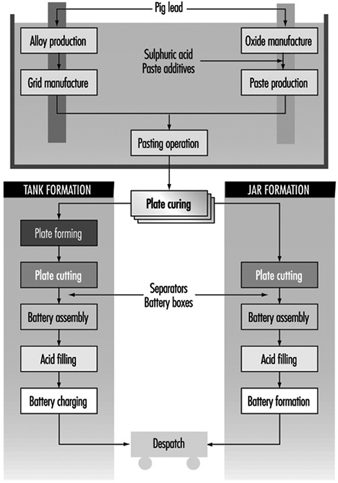
Oxide manufacture: Lead oxide is manufactured from pigs of lead (masses of lead from smelting furnaces) by one of two methods—a Barton Pot or a milling process. In the Barton Pot process, air is blown over molten lead to produce a fine stream of lead droplets. The droplets react with oxygen in the air to form the oxide, which consists of a core of lead with a lead oxide (PbO) coating.
In the milling process, solid lead (which may range in size from small balls to complete pigs) is fed into a rotating mill. The tumbling action of the lead generates heat and the surface of the lead oxidizes. As the particles roll around in the drum, the surface layers of oxide are removed to expose more clean lead for oxidation. The airstream carries the powder to a bag filter, where it is collected.
Grid production: Grids are produced mainly by casting (both automatic and manual) or, particularly for automotive batteries, expansion from wrought or cast lead alloy.
Pasting: Battery paste is made by mixing the oxide with water, sulphuric acid and a range of proprietary additives. The paste is pressed by machine or hand into the grid lattice, and the plates are usually flash-dried in a high-temperature oven.
Pasted plates are cured by storing them in ovens under carefully controlled conditions of temperature, humidity and time. Free lead in the paste converts to lead oxide.
Formation, plate cutting and assembly: Battery plates undergo an electrical formation process in one of two ways. In tank formation, plates are loaded into large baths of dilute sulphuric acid and a direct current is passed to form the positive and negative plates. After drying, the plates are cut and assembled, with separators between them, into battery boxes. Plates of like polarity are connected by welding together the plate lugs.
In jar formation, the plates are electrically formed after being assembled into battery boxes.
Occupational Health Hazards and Controls
Lead
Lead is the major health hazard associated with battery manufacture. The principal exposure route is through inhalation, but ingestion can also pose a problem if insufficient attention is paid to personal hygiene. Exposure can occur at all stages of production.
Lead oxide manufacture is potentially very hazardous. Exposures are controlled by automating the process, thus removing the workers from the hazard. In many factories the process is operated by one person.
In grid casting, exposures to lead fumes are minimized by the use of local exhaust ventilation (LEV) together with thermostatic control of lead pots (lead fume emissions increase markedly above 500 C). Lead-bearing dross, which forms on top of the molten lead, can also cause problems. The dross contains a large amount of very fine dust, and great care has to be exercised when disposing of it.
Pasting areas have traditionally resulted in high lead exposures. The manufacturing method often results in splashes of lead slurry getting onto machinery, the floor, aprons and boots. These splashes dry out and produce airborne lead dust. Control is achieved by keeping the floor permanently wetted and frequently sponging down aprons.
Lead exposures in other departments (forming, plate cutting and assembly) occur through handling dry, dusty plates. Exposures are minimized by LEV together with appropriate use of personal protective equipment.
Many countries have legislation in place to limit the degree of occupational exposure, and numerical standards exist for lead-in-air and blood lead levels.
An occupational health professional is normally employed to take blood samples from exposed workers. The frequency of blood testing can range from annual for low-risk workers to quarterly for those in high-risk departments (e.g., pasting). If a worker’s blood lead level exceeds the statutory limit, then the worker should be removed from any work exposure to lead until the blood lead falls to a level deemed acceptable by the medical adviser.
Air sampling for lead is complementary to blood lead testing. Personal, rather than static, sampling is the preferred method. A large number of lead-in-air samples is usually required because of the inherent variability in results. Use of the correct statistical procedures in analysing the data can give information on sources of lead and can provide a basis for making improvements to engineering design. Regular air sampling can be used to assess the continuing effectiveness of control systems.
The allowable lead-in-air concentrations and blood lead concentrations vary from country to country, and presently range from 0.05 to 0.20 mg/m3 and 50 to 80 mg/dl respectively. There is a continuing downward trend in these limits.
In addition to the normal engineering controls, other measures are necessary to minimize lead exposures. There should be no eating, smoking, drinking or gum chewing in any production area.
Suitable washing and changing facilities should be provided to enable work clothing to be kept in a separate area from personal clothing and footwear. Washing/shower facilities should be located between the clean and dirty areas.
Sulphuric acid
During the formation process the active material on the plates is converted to PbO2 at the positive and Pb at the negative electrode. As the plates become fully charged, the formation current begins to dissociate the water in the electrolyte into hydrogen and oxygen:
Positive: ![]()
Negative: ![]()
Gassing generates sulphuric acid mist. Tooth erosion was, at one time, a common feature among workers in formation areas. Battery companies have traditionally employed the services of a dentist, and many continue to do so.
Recent studies (IARC 1992) have suggested a possible link between exposures to inorganic acid mists (including sulphuric acid) and cancer of the larynx. Research continues in this area.
The occupational exposure standard in the UK for sulphuric acid mist is 1 mg/m3. Exposures can be kept below this level with LEV in place over the formation circuits.
Skin exposure to the corrosive sulphuric acid liquid is also of concern. Precautions include personal protection equipment, eyewash fountains and emergency showers.
Talc
Talc is used in certain hand-casting operations as a mould release agent. Long-term exposure to talc dust can cause pneumoconiosis, and it is important that the dust be controlled by suitable ventilation and process control measures.
Man-made mineral fibres (MMFs)
Separators are used in lead-acid batteries to electrically insulate the positive from the negative plates. Various types of material have been used over the years (e.g., rubber, cellulose, polyvinyl chloride (PVC), polyethylene), but, increasingly, glass fibre separators are being used. These separators are manufactured from MMFs.
An increased risk of lung cancer amongst workers was demonstrated in the early days of the mineral wool industry (HSE 1990). However, this may have been caused by other carcinogenic materials in use at the time. It is prudent nevertheless to ensure that any exposure to MMFs is kept to a minimum by either total enclosure or LEV.
Stibine and arsine
Antimony and arsenic are commonly used in lead alloys, and stibine (SbH3) or arsine (AsH3) can be produced under certain circumstances:
- when a cell is given excessive overcharge
- when dross from a lead calcium alloy is mixed with dross from a lead antimony or lead arsenic alloy. The two drosses can react chemically to form calcium stibide or calcium arsenide which, on subsequent wetting, can generate SbH3 or AsH3.
Stibine and arsine are both highly toxic gases which act by destroying red blood cells. Strict process controls during battery manufacture should prevent any risk of exposure to these gases.
Physical hazards
A variety of physical hazards also exists in battery manufacturing (e.g., noise, molten metal and acid splashes, electrical hazards and manual handling), but the risks from these can be reduced by appropriate engineering and process controls.
Environmental Issues
The effect of lead on the health of children has been extensively studied. It is therefore very important that environmental releases of lead be kept to a minimum. For battery factories, the most polluting air emissions should be filtered. All process waste (usually an acidic lead-bearing slurry) should be processed at an effluent treatment plant to neutralize the acid and settle out the lead from the suspension.
Future Developments
It is likely that there will be increasing restrictions on the use of lead in the future. In an occupational sense this will result in increasing automation of processes so that the worker is removed from the hazard.
Copper, Lead and Zinc Smelting and Refining
Adapted from EPA 1995.
Copper
Copper is mined in both open pits and underground mines, depending upon the ore grade and the nature of the ore deposit. Copper ore typically contains less that 1% copper in the form of sulphide minerals. Once the ore is delivered above the ground, it is crushed and ground to a powdery fineness and then concentrated for further processing. In the concentration process, ground ore is slurried with water, chemical reagents are added and air is blown through the slurry. The air bubbles attach themselves to the copper minerals and are then skimmed off the top of the flotation cells. The concentrate contains between 20 and 30% copper. The tailings, or gangue minerals, from the ore fall to the bottom of the cells and are removed, dewatered by thickeners and transported as a slurry to a tailings pond for disposal. All water used in this operation, from dewatering thickeners and the tailings pond, is recovered and recycled back into the process.
Copper can be produced either pyrometallurgically or hydrometallurgically depending upon the ore-type used as a charge. The ore concentrates, which contain copper sulphide and iron sulphide minerals, are treated by pyrometallurgical processes to yield high purity copper products. Oxide ores, which contain copper oxide minerals that may occur in other parts of the mine, together with other oxidized waste materials, are treated by hydrometallurgical processes to yield high purity copper products.
Copper conversion from the ore to metal is accomplished by smelting. During smelting the concentrates are dried and fed into one of several different types of furnaces. There the sulphide minerals are partially oxidized and melted to yield a layer of matte, a mixed copper-iron sulphide and slag, an upper layer of waste.
The matte is further processed by converting. The slag is tapped from the furnace and stored or discarded in slag piles onsite. A small amount of slag is sold for railroad ballast and for sand blasting grit. A third product of the smelting process is sulphur dioxide, a gas which is collected, purified and made into sulphuric acid for sale or for use in hydrometallurgical leaching operations.
Following smelting, the copper matte is fed into a converter. During this process the copper matte is poured into a horizontal cylindrical vessel (approximately 10ґ4 m) fitted with a row of pipes. The pipes, known as tuyères, project into the cylinder and are used to introduce air into the converter. Lime and silica are added to the copper matte to react with the iron oxide produced in the process to form slag. Scrap copper may also be added to the converter. The furnace is rotated so that the tuyères are submerged, and air is blown into the molten matte causing the remainder of the iron sulphide to react with oxygen to form iron oxide and sulphur dioxide. Then the converter is rotated to pour off the iron silicate slag.
Once all of the iron is removed, the converter is rotated back and given a second blow of air during which the remainder of the sulphur is oxidized and removed from the copper sulphide. The converter is then rotated to pour off the molten copper, which at this point is called blister copper (so named because if allowed to solidify at this point, it will have a bumpy surface due to the presence of gaseous oxygen and sulphur). Sulphur dioxide from the converters is collected and fed into the gas purification system together with that from the smelting furnace and made into sulphuric acid. Due to its residual copper content, slag is recycled back to the smelting furnace.
Blister copper, containing a minimum of 98.5% copper, is refined to high purity copper in two steps. The first step is fire refining, in which the molten blister copper is poured into a cylindrical furnace, similar in appearance to a converter, where first air and then natural gas or propane are blown through the melt to remove the last of the sulphur and any residual oxygen from the copper. The molten copper is then poured into a casting wheel to form anodes pure enough for electrorefining.
In electrorefining, the copper anodes are loaded into electrolytic cells and interspaced with copper starting sheets, or cathodes, in a bath of copper sulphate solution. When a direct current is passed through the cell the copper is dissolved from the anode, transported through the electrolyte and re-deposited on the cathode starting sheets. When the cathodes have built-up to sufficient thickness they are removed from the electrolytic cell and a new set of starting sheets is put in their place. Solid impurities in the anodes fall to the bottom of the cell as a sludge where they are ultimately collected and processed for the recovery of precious metals such as gold and silver. This material is known as anode slime.
The cathodes removed from the electrolytic cell are the primary product of the copper producer and contain 99.99% copper. These may be sold to wire-rod mills as cathodes or processed further to a product called rod. In manufacturing rod, cathodes are melted in a shaft furnace and the molten copper is poured onto a casting wheel to form a bar suitable for rolling into a 3/8 inch diameter continuous rod. This rod product is shipped to wire mills where it is extruded into various sizes of copper wire.
In the hydrometallurgical process, the oxidized ores and waste materials are leached with sulphuric acid from the smelting process. Leaching is performed in situ, or in specially prepared piles by distributing acid across the top and allowing it to percolate down through the material where it is collected. The ground under the leach pads is lined with an acid-proof, impermeable plastic material to prevent leach liquor from contaminating groundwater. Once the copper-rich solutions are collected they can be processed by either of two processes—the cementation process or the solvent extraction/electrowinning process (SXEW). In the cementation process (which is rarely used today), the copper in the acidic solution is deposited on the surface of scrap iron in exchange for the iron. When sufficient copper has been cemented out, the copper-rich iron is put into the smelter together with the ore concentrates for copper recovery via the pyrometallurgical route.
In the SXEW process, the pregnant leach solution (PLS) is concentrated by solvent extraction, which extracts copper but not impurity metals (iron and other impurities). The copper-laden organic solution is then separated from the leachate in a settling tank. Sulphuric acid is added to the pregnant organic mixture, which strips the copper into an electrolytic solution. The leachate, containing the iron and other impurities, is returned to the leaching operation where its acid is used for further leaching. The copper-rich strip solution is passed into an electrolytic cell known as an electrowinning cell. An electrowinning cell differs from an electrorefining cell in that it uses a permanent, insoluble anode. The copper in solution is then plated onto a starting sheet cathode in much the same manner as it is on the cathode in an electrorefining cell. The copper-depleted electrolyte is returned to the solvent extraction process where it is used to strip more copper from the organic solution. The cathodes produced from the electrowinning process are then sold or made into rods in the same manner as those produced from the electrorefining process.
Electrowinning cells are used also for the preparation of starting sheets for both the electrorefining and electrowinning processes by plating the copper onto either stainless steel or titanium cathodes and then stripping off the plated copper.
Hazards and their prevention
The major hazards are exposure to ore dusts during ore processing and smelting, metal fumes (including copper, lead and arsenic) during smelting, sulphur dioxide and carbon monoxide during most smelting operations, noise from crushing and grinding operations and from furnaces, heat stress from the furnaces and sulphuric acid and electrical hazards during electrolytic processes.
Precautions include: LEV for dusts during transfer operations; local exhaust and dilution ventilation for sulphur dioxide and carbon monoxide; a noise control and hearing protection programme; protective clothing and shields, rest breaks and fluids for heat stress; and LEV, PPE and electrical precautions for electrolytic processes. Respiratory protection is commonly worn to protect against dusts, fumes and sulphur dioxide.
Table 1 lists environmental pollutants for various steps in copper smelting and refining.
Table 1. Process materials inputs and pollution outputs for copper smelting and refining
|
Process |
Material input |
Air emissions |
Process wastes |
Other wastes |
|
Copper concentration |
Copper ore, water, chemical reagents, thickeners |
Flotation wastewaters |
Tailings containing waste minerals such as limestone and quartz |
|
|
Copper leaching |
Copper concentrate, sulphuric acid |
Uncontrolled leachate |
Heap leach waste |
|
|
Copper smelting |
Copper concentrate, siliceous flux |
Sulphur dioxide, particulate matter containing arsenic, antimony, cadmium, lead, mercury and zinc |
Acid plant blowdown slurry/sludge, slag containing iron sulphides, silica |
|
|
Copper conversion |
Copper matte, scrap copper, siliceous flux |
Sulphur dioxide, particulate matter containing arsenic, antimony, cadmium, lead, mercury and zinc |
Acid plant blowdown slurry/sludge, slag containing iron sulphides, silica |
|
|
Electrolytic copper refining |
Blister copper, sulphuric acid |
Slimes containing impurities such as gold, silver, antimony, arsenic, bismuth, iron, lead, nickel, selenium, sulphur and zinc |
Lead
The primary lead production process consists of four steps: sintering, smelting, drossing and pyrometallurgical refining. To begin, a feedstock comprising mainly of lead concentrate in the form of lead sulphide is fed into a sintering machine. Other raw materials may be added including iron, silica, limestone flux, coke, soda, ash, pyrite, zinc, caustic and particulates gathered from pollution control devices. In the sintering machine the lead feedstock is subjected to blasts of hot air which burn off the sulphur, creating sulphur dioxide. The lead oxide material existing after this process contains about 9% of its weight in carbon. The sinter is then fed along with coke, various recycled and cleanup materials, limestone and other fluxing agents into a blast furnace for reducing, where the carbon acts as a fuel and smelts or melts the lead material. The molten lead flows to the bottom of the furnace where four layers form: “speiss” (the lightest material, basically arsenic and antimony); “matte” (copper sulphide and other metal sulphides); blast furnace slag (primarily silicates); and lead bullion (98% lead, by weight). All layers are then drained off. The speiss and matte are sold to copper smelters for recovery of copper and precious metals. The blast furnace slag which contains zinc, iron, silica and lime is stored in piles and partially recycled. Sulphur oxide emissions are generated in blast furnaces from small quantities of residual lead sulphide and lead sulphates in the sinter feed.
Rough lead bullion from the blast furnace usually requires preliminary treatment in kettles before undergoing refining operations. During drossing, the bullion is agitated in a drossing kettle and cooled to just above its freezing point (370 to 425°C). A dross, which is composed of lead oxide, along with copper, antimony and other elements, floats to the top and solidifies above the molten lead.
The dross is removed and fed into a dross furnace for recovery of the non-lead useful metals. To enhance copper recovery, drossed lead bullion is treated by adding sulphur-bearing materials, zinc, and/or aluminium, lowering the copper content to approximately 0.01%.
During the fourth step, the lead bullion is refined using pyrometallurgical methods to remove any remaining non-lead saleable materials (e.g., gold, silver, bismuth, zinc, and metal oxides such as antimony, arsenic, tin and copper oxide). The lead is refined in a cast iron kettle by five stages. Antimony, tin and arsenic are removed first. Then zinc is added and gold and silver are removed in the zinc slag. Next, the lead is refined by vacuum removal (distillation) of zinc. Refining continues with the addition of calcium and magnesium. These two materials combine with bismuth to form an insoluble compound that is skimmed from the kettle. In the final step caustic soda and/or nitrates may be added to the lead to remove any remaining traces of metal impurities. The refined lead will have a purity of 99.90 to 99.99% and may be mixed with other metals to form alloys or it may be directly cast into shapes.
Hazards and their prevention
The major hazards are exposure to ore dusts during ore processing and smelting, metal fumes (including lead, arsenic and antimony) during smelting, sulphur dioxide and carbon monoxide during most smelting operations, noise from grinding and crushing operations and from furnaces, and heat stress from the furnaces.
Precautions include: LEV for dusts during transfer operations; local exhaust and dilution ventilation for sulphur dioxide and carbon monoxide; a noise control and hearing protection programme; and protective clothing and shields, rest breaks and fluids for heat stress. Respiratory protection is commonly worn to protect against dusts, fumes and sulphur dioxide. Biological monitoring for lead is essential.
Table 2 lists environmental pollutants for various steps in lead smelting and refining.
Table 2. Process materials inputs and pollution outputs for lead smelting and refining
|
Process |
Material input |
Air emissions |
Process wastes |
Other wastes |
|
Lead sintering |
Lead ore, iron, silica, limestone flux, coke, soda, ash, pyrite, zinc, caustic, baghouse dust |
Sulphur dioxide, particulate matter contain-ing cadmium and lead |
||
|
Lead smelting |
Lead sinter, coke |
Sulphur dioxide, particulate matter contain-ing cadmium and lead |
Plant washdown wastewater, slag granulation water |
Slag containing impurities such as zinc, iron, silica and lime, surface impoundment solids |
|
Lead drossing |
Lead bullion, soda ash, sulphur, baghouse dust, coke |
Slag containing such impurities as copper, surface impoundment solids |
||
|
Lead refining |
Lead drossing bullion |
Zinc
Zinc concentrate is produced by separating the ore, which may contain as little as 2% zinc, from waste rock by crushing and flotation, a process normally performed at the mining site. The zinc concentrate is then reduced to zinc metal in one of two ways: either pyrometallurgically by distillation (retorting in a furnace) or hydrometallurgically by electrowinning. The latter accounts for approximately 80% of total zinc refining.
Four processing stages are generally used in hydrometallurgic zinc refining: calcining, leaching, purification and electrowinning. Calcining, or roasting, is a high-temperature process (700 to 1000 °C) that converts zinc sulphide concentrate to an impure zinc oxide called calcine. Roaster types include multiple-hearth, suspension or fluidized-bed. In general, calcining begins with the mixing of zinc-containing materials with coal. This mixture is then heated, or roasted, to vaporize the zinc oxide which is then moved out of the reaction chamber with the resulting gas stream. The gas stream is directed to the baghouse (filter) area where the zinc oxide is captured in baghouse dust.
All of the calcining processes generate sulphur dioxide, which is controlled and converted to sulphuric acid as a marketable process by-product.
Electrolytic processing of desulphurized calcine consists of three basic steps: leaching, purification and electrolysis. Leaching refers to the dissolving of the captured calcine in a solution of sulphuric acid to form a zinc sulphate solution. The calcine may be leached once or twice. In the double-leach method, the calcine is dissolved in a slightly acidic solution to remove the sulphates. The calcine is then leached a second time in a stronger solution which dissolves the zinc. This second leaching step is actually the beginning of the third step of purification because many of the iron impurities drop out of the solution as well as the zinc.
After leaching, the solution is purified in two or more stages by adding zinc dust. The solution is purified as the dust forces deleterious elements to precipitate so that they can be filtered out. Purification is usually conducted in large agitation tanks. The process takes place at temperatures ranging from 40 to 85°C and pressures ranging from atmospheric to 2.4 atmospheres. The elements recovered during purification include copper as a cake and cadmium as a metal. After purification the solution is ready for the final step, electrowinning.
Zinc electrowinning takes place in an electrolytic cell and involves running an electric current from a lead-silver alloy anode through the aqueous zinc solution. This process charges the suspended zinc and forces it to deposit onto an aluminium cathode which is immersed in the solution. Every 24 to 48 hours, each cell is shut down, the zinc-coated cathodes removed and rinsed, and the zinc mechanically stripped from the aluminium plates. The zinc concentrate is then melted and cast into ingots and is often as high as 99.995% pure.
Electrolytic zinc smelters contain as many as several hundred cells. A portion of the electrical energy is converted into heat, which increases the temperature of the electrolyte. Electrolytic cells operate at temperature ranges from 30 to 35°C at atmospheric pressure. During electrowinning a portion of the electrolyte passes through cooling towers to decrease its temperature and to evaporate the water it collects during the process.
Hazards and their prevention
The major hazards are exposure to ore dusts during ore processing and smelting, metal fumes (including zinc and lead) during refining and roasting, sulphur dioxide and carbon monoxide during most smelting operations, noise from crushing and grinding operations and from furnaces, heat stress from the furnaces and sulphuric acid and electrical hazards during electrolytic processes.
Precautions include: LEV for dusts during transfer operations; local exhaust and dilution ventilation for sulphur dioxide and carbon monoxide; a noise control and hearing protection programme; protective clothing and shields, rest breaks and fluids for heat stress; and LEV, PPE, and electrical precautions for electrolytic processes. Respiratory protection is commonly worn to protect against dusts, fumes and sulphur dioxide.
Table 3 lists environmental pollutants for various steps in zinc smelting and refining.
Table 3. Process materials inputs and pollution outputs for zinc smelting and refining
|
Process |
Material input |
Air emissions |
Process wastes |
Other wastes |
|
Zinc calcining |
Zinc ore, coke |
Sulphur dioxide, particulate matter containing zinc and lead |
Acid plant blowdown slurry |
|
|
Zinc leaching |
Zinc calcine, sulphuric acid, limestone, spent electrolyte |
Wastewaters containing sulphuric acid |
||
|
Zinc purification |
Zinc-acid solution, zinc dust |
Wastewaters containing sulphuric acid, iron |
Copper cake, cadmium |
|
|
Zinc electrowinning |
Zinc in a sulphuric acid/aqueous solution, lead-silver alloy anodes, aluminium cathodes, barium carbonate or strontium, colloidal additives |
Dilute sulphuric acid |
Electrolytic cell slimes/sludges |
Batteries
The term battery refers to a collection of individual cells, which can generate electricity though chemical reactions. Cells are categorized as either primary or secondary. In primary cells, the chemical reactions that produce the electron flow are not reversible, and therefore the cells are not easily recharged. Conversely, secondary cells must be charged prior to their use, which is achieved by passing an electrical current through the cell. Secondary cells have the advantage that they can often be repeatedly recharged and discharged through use.
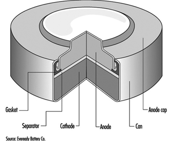
The classic primary battery in everyday use is the Leclanché dry cell, so called because the electrolyte is a paste, not a liquid. The Leclanché cell is typified by the cylindrical batteries used in flashlights, portable radios, calculators, electric toys and the like. In recent years, alkaline batteries, such as the zinc-manganese dioxide cell, have become more prevalent for this type of use. Miniature or “button” batteries have found use in hearing aids, computers, watches, cameras and other electronic equipment. The silver oxide-zinc cell, mercury cell, the zinc-air cell, and the lithium-manganese dioxide cell are some examples. See figure 1 for a cutaway view of a typical alkaline miniature battery.
Figure 1. Cutaway view of alkaline miniature battery
The classic secondary or storage battery is the lead-acid battery, widely used in the transportation industry. Secondary batteries are also used in power plants and industry. Rechargeable, battery-operated tools, toothbrushes, flashlights and the like are a new market for secondary cells. Nickel-cadmium secondary cells are becoming more popular, especially in pocket cells for emergency lighting, diesel starting and stationary and traction applications, where the reliability, long life, frequent rechargeability and low-temperature performance outweigh their extra cost.
Rechargeable batteries under development for use in electric vehicles utilize lithium-ferrous sulphide, zinc-chlorine and sodium-sulphur.
Table 1 gives the composition of some common batteries.
Table 1. Composition of common batteries
|
Type of battery |
Negative electrode |
Positive electrode |
Electrolyte |
|
Primary cells |
|||
|
Leclanché dry cell |
Zinc |
Manganese dioxide |
Water, zinc chloride, ammonium chloride |
|
Alkaline |
Zinc |
Manganese dioxide |
Potassium hydroxide |
|
Mercury (Ruben’s cell) |
Zinc |
Mercuric oxide |
Potassium hydroxide, zinc oxide, water |
|
Silver |
Zinc |
Silver oxide |
Potassium hydroxide, zinc oxide, water |
|
Lithium |
Lithium |
Manganese dioxide |
Lithium chlorate, LiCF3SO3 |
|
Lithium |
Lithium |
Sulphur dioxide |
Sulphur dioxide, acetonitrile, lithium bromide |
|
Thionyl chloride |
Lithium aluminium chloride |
||
|
Zinc in air |
Zinc |
Oxygen |
Zinc oxide, potassium hydroxide |
|
Secondary cells |
|||
|
Lead-acid |
Lead |
Lead dioxide |
Dilute sulphuric acid |
|
Nickel-iron (Edison battery) |
Iron |
Nickel oxide |
Potassium hydroxide |
|
Nickel-cadmium |
Cadmium hydroxide |
Nickel hydroxide |
Potassium hydroxide, possibly lithium hydroxide |
|
Silver-zinc |
Zinc powder |
Silver oxide |
Potassium hydroxide |
Manufacturing Processes
While there are clear differences in the manufacture of the different types of batteries, there are several processes which are common: weighing, grinding, mixing, compressing and drying of constituent ingredients. In modern battery plants many of these processes are enclosed and highly automated, using sealed equipment. Therefore, exposure to the various ingredients can occur during weighing and loading and during cleaning of the equipment.
In older battery plants, many of the grinding, mixing and other operations are done manually, or the transfer of ingredients from one step of the process to another is done manually. In these instances, the risk of inhalation of dusts or skin contact with corrosive substances is high. Precautions for dust-producing operations include total enclosure and mechanized handling and weighing of powders, local exhaust ventilation, daily wet mopping and/or vacuuming and wearing of respirators and other personal protective equipment during maintenance operations.
Noise is also a hazard, since compressing machines and wrapping machines are noisy. Noise control methods and hearing conservation programmes are essential.
The electrolytes in many batteries contain corrosive potassium hydroxide. Enclosure and skin and eye protection are indicated precautions. Exposures can also occur to the particulates of toxic metals such as cadmium oxide, mercury, mercuric oxide, nickel and nickel compounds, and lithium and lithium compounds, which are used as anodes or cathodes in particular types of batteries. The lead-acid storage battery, sometimes referred to as the accumulator, can involve considerable lead exposure hazards and is discussed separately in the article “Lead-acid battery manufacture”.
Lithium metal is highly reactive, thus lithium batteries must be assembled in a dry atmosphere in order to avoid the lithium reacting with water vapour. Sulphur dioxide and thionyl chloride, used in some lithium batteries, are respiratory hazards. Hydrogen gas, used in nickel-hydrogen batteries, is a fire and explosion hazard. These, as well as materials in newly developed batteries, will require special precautions.
Leclanché Cells
Leclanché dry-cell batteries are produced as shown in figure 2. The positive electrode or cathode mixture comprises 60 to 70% manganese dioxide, the remainder being made up of graphite, acetylene black, ammonium salts, zinc chloride and water. Dry, finely ground manganese dioxide, graphite and acetylene black are weighed and fed into a grinder-mixer; electrolyte containing water, zinc chloride and ammonium chloride is added, and the prepared mixture is pressed on a hand-fed tableting or agglomerating press. In certain cases, the mixture is dried in an oven, sifted and remoistened before tableting. The tablets are inspected and wrapped on hand-fed machines after being allowed to harden for a few days. The agglomerates are then placed in trays and soaked in electrolyte, and are now ready for assembly.
Figure 2. Leclanché cell battery production

The anode is the zinc case, which is prepared from zinc blanks on a hot press (or zinc sheets are folded and welded to the case). An organic gelatinous paste consisting of maize and flour starches soaked in electrolyte is mixed in large vats. The ingredients are usually poured in from sacks without weighing. The mixture is then purified with zinc chips and manganese dioxide. Mercuric chloride is added to the electrolyte to form an amalgam with the interior of the zinc container. This paste will form the conducting medium or electrolyte.
Cells are assembled by automatic pouring of the required amount of gelatinous paste into the zinc cases to form an inner sleeve lining on the zinc container. In some cases, the cases receive a chromate finish by the pouring in and emptying of a mixture of chromic and hydrochloric acid before adding the gelatinous paste. The cathode agglomerate is then placed in position in the centre of the case. A carbon rod is placed centrally in the cathode to act as the current collector.
The zinc cell is then sealed with molten wax or paraffin and heated with a flame to give a better seal. The cells are then welded together to form the battery. The reaction of the battery is:
2 MnO2 + 2 NH4Cl + Zn → ZnCl2 + H2O2 + Mn2O3
Workers may be exposed to manganese dioxide during weighing, mixer loading, grinding, cleaning the oven, sifting, hand pressing and wrapping, depending on the degree of automation, sealed enclosure and local exhaust ventilation. In manual pressing and wet wrapping, there may be exposure to the wet mixture, which can dry to produce inhalable dust; dermatitis may occur from exposure to the slightly corrosive electrolyte. Personal hygiene measures, gloves and respiratory protection for cleaning and maintenance operations, showering facilities and separate lockers for work and street clothes can reduce these risks. As mentioned above, noise hazards can result from the wrapping and tableting press.
Mixing is automatic during manufacture of the gelatinous paste, and the only exposure is during addition of the materials. During addition of mercuric chloride to the gelatinous paste, there is the risk of inhalation and skin absorption and possible mercury poisoning. LEV or personal protective equipment is necessary.
Exposure to spills of chromic acid and hydrochloric acid during chromating and exposure to welding fumes and fumes from heating the sealing compound are also possible. Mechanization of the chromating process, use of gloves and LEV for heat sealing and welding are suitable precautions.
Nickel-Cadmium Batteries
The most common method today of making nickel-cadmium electrodes is by depositing the active electrode material directly into a porous sintered nickel substrate, or plate. (See figure 3.) The plate is prepared by pressing a paste of sintered grade nickel powder (often made by decomposition of nickel carbonyl) into the open grid of nickel-plated perforated sheet steel (or nickel gauze or nickel-plated steel gauze) and then sintering or drying in an oven. These plates may then be cut, weighed and coined (compressed) for particular purposes or rolled into a spiral for household-type cells.
Figure 3. Nickel-cadmium battery production
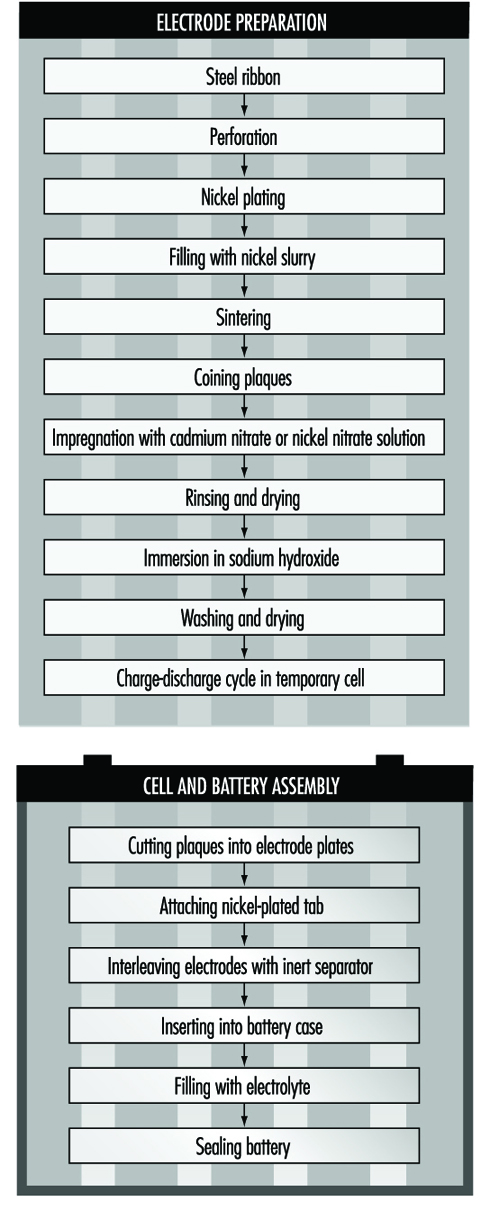
The sintered plaque is then impregnated with nickel nitrate solution for the positive electrode or cadmium nitrate for the negative electrode. These plaques are rinsed and dried, immersed in sodium hydroxide to form nickel hydroxide or cadmium hydroxide and washed and dried again. Usually the next step is to immerse the positive and negative electrodes in a large temporary cell containing 20 to 30% sodium hydroxide. Charge-discharge cycles are run to remove impurities and the electrodes are removed, washed and dried.
An alternative way of making cadmium electrodes is to prepare a paste of cadmium oxide mixed with graphite, iron oxide and paraffin, which is milled and finally compacted between rollers to form the active material. This is then pressed into a moving perforated steel strip that is dried, sometimes compressed, and cut into plates. Lugs may be attached at this stage.
The next steps involve cell and battery assembly. For large batteries, the individual electrodes are then assembled into electrode groups with plates of opposite polarity interleaved with plastic separators. These electrode groups may be bolted or welded together and placed in a nickel-plated steel casing. More recently, plastic battery casings have been introduced. The cells are filled with an electrolyte solution of potassium hydroxide, which may also contain lithium hydroxide. The cells are then assembled into batteries and bolted together. Plastic cells may be cemented or taped together. Each cell is connected with a lead connector to the adjacent cell, leaving a positive and negative terminal at the ends of the battery.
For cylindrical batteries, the impregnated plates are assembled into electrode groups by winding the positive and negative electrodes, separated by an inert material, into a tight cylinder. The electrode cylinder is then placed in a nickel-plated metal case, potassium hydroxide electrolyte is added and the cell is sealed by welding.
The chemical reaction involved in the charging and discharging of nickel-cadmium batteries is:
![]()
The major potential exposure to cadmium occurs from handling of cadmium nitrate and its solution while making paste from cadmium oxide powder and handling the dried active powders. Exposure can also occur during reclamation of cadmium from scrap plates. Enclosure and automated weighing and mixing can reduce these hazards during the early steps.
Similar measures can control exposures to nickel compounds. The production of sintered nickel from nickel carbonyl, although done in sealed machinery, involves potential exposure to extremely toxic nickel carbonyl and carbon monoxide. The process requires continuous monitoring for gas leaks.
The handling of caustic potassium or lithium hydroxide requires suitable ventilation and personal protection. Welding generates fumes and requires LEV.
Health Effects and Disease Patterns
The most serious health hazards in traditional battery making are lead, cadmium, mercury and manganese dioxide exposures. Lead hazards are discussed elsewhere in this chapter and Encyclopaedia. Cadmium can cause kidney disease and is carcinogenic. Cadmium exposure was found to be widespread in US nickel-cadmium battery plants, and many workers have had to be medically removed under the Occupational Safety and Health Administration’s Cadmium Standard provisions due to high cadmium levels in blood and urine (McDiarmid et al. 1996). Mercury affects the kidneys and nervous system. Excessive exposure to mercury vapour has been shown in studies of several mercury battery plants (Telesca 1983). Manganese dioxide exposures have been shown to be high in powder mixing and handling in alkaline dry cell manufacturing (Wallis, Menke and Chelton 1993). This can result in neurofunctional deficits in battery workers (Roels et al. 1992). Manganese dusts can, if absorbed in excessive quantities, lead to disorders of the central nervous system similar to Parkinson’s syndrome. Other metals of concern include nickel, lithium, silver and cobalt.
Skin burns can result from exposure to zinc chloride, potassium hydroxide, sodium hydroxide and lithium hydroxide solutions used in the electrolytes of batteries.
Aluminium Smelting and Refining
Process Overview
Bauxite is extracted by open-pit mining. The richer ores are used as mined. The lower grade ores may be beneficiated by crushing and washing to remove clay and silica waste. The production of the metal comprises two basic steps:
- Refining. Production of alumina from bauxite by the Bayer process in which bauxite is digested at high temperature and pressure in a strong solution of caustic soda. The resulting hydrate is crystallized and calcined to the oxide in a kiln or fluid bed calciner.
- Reduction. Reduction of alumina to virgin aluminium metal employing the Hall-Heroult electrolytic process using carbon electrodes and cryolite flux.
Experimental development suggests that in the future aluminium may be reduced to the metal by direct reduction from the ore.
There are presently two major types of Hall-Heroult electrolytic cells in use. The so-called “pre-bake” process utilizes electrodes manufactured as noted below. In such smelters exposure to polycyclic hydrocarbons normally occurs in the electrode manufacturing facilities, especially during mixing mills and forming presses. Smelters utilizing the Soderberg-type cell do not require facilities for the manufacture of baked carbon anodes. Rather, the mixture of coke and pitch binder is put into hoppers whose lower ends are immersed in the molten cryolite-alumina bath mixture. As the mixture of pitch and coke is heated by the molten metal-cryolite bath within the cell, this mixture bakes into a hard graphitic mass in situ. Metal rods are inserted into the anodic mass as conductors for a direct current electric flow. These rods must be replaced periodically; in extracting these, considerable amounts of coal tar pitch volatiles are evolved into the cell room environment. To this exposure is added those pitch volatiles generated as the baking of the pitch-coke mass proceeds.
Within the last decade the industry has tended to either not replace or to modify existent Soderberg type reduction facilities as a consequence of the demonstrated carcinogenic hazard they present. In addition, with the increasing automation of reduction cell operations—particularly the changing of anodes, tasks are more commonly performed from enclosed mechanical cranes. Consequently worker exposures and the risk of developing those disorders associated with aluminium smelting are gradually decreasing in modern facilities. By contrast, in those economies wherein adequate capital investment is not readily available, the persistence of older, manually operated reduction processes will continue to present the risks of those occupational disorders (see below) previously associated with aluminium reduction plants. Indeed, this tendency will tend to become more aggravated in such older, unimproved operations, especially as they age.
Carbon electrode manufacture
The electrodes required by pre-bake electrolytic reduction to pure metal are normally made by a facility associated with this type of aluminium smelting plant. The anodes and cathodes are most frequently made from a mixture of ground petroleum-derived coke and pitch. Coke first is ground in ball mills, then conveyed and mixed mechanically with the pitch and finally cast into blocks in a moulding presses. These anode or cathode blocks are next heated in a gas-fired furnace for several days until they form hard graphitic masses with essentially all volatiles having been driven off. Finally they are attached to anode rods or saw-grooved to receive the cathode bars.
It should be noted that the pitch used to form such electrodes represents a distillate which is derived from coal or petroleum tar. In the conversion of this tar to pitch by heating, the final pitch product has boiled off essentially all of its low-boiling point inorganics, e.g., SO2, as well as aliphatic compounds and one- and two ring aromatic compounds. Thus, such pitch should not present the same hazards in its use as coal or petroleum tars since these classes of compounds ought not to be present. There are some indications that the carcinogenic potential of such pitch products may not be as great as the more complex mixture of tars and other volatiles associated with the incomplete combustion of coal.
Hazards and Their Prevention
The hazards and preventive measures for aluminium smelting and refining processes are basically the same as those found in smelting and refining in general; however, the individual processes present certain specific hazards.
Mining
Although sporadic references to “bauxite lung” occur in the literature, there is little convincing evidence that such an entity exists. However, the possibility of the presence of crystalline silica in bauxite ores should be considered.
Bayer process
The extensive use of caustic soda in the Bayer process presents frequent risks of chemical burns of the skin and eyes. Descaling of tanks by pneumatic hammers is responsible for severe noise exposure. The potential hazards associated with the inhalation of excessive doses of aluminium oxide produced in this process are discussed below.
All workers involved in the Bayer process should be well informed of the hazards associated with handling caustic soda. In all sites at risk, eyewash fountains and basins with running water and deluge showers should be provided, with notices explaining their use. PPE (e.g., goggles, gloves, aprons and boots) should be supplied. Showers and double locker accommodations (one locker for work clothing, the other for personal clothing) should be provided and all employees encouraged to wash thoroughly at the end of the shift. All workers handling molten metal should be supplied with visors, respirators, gauntlets, aprons, armlets and spats to protect them against burns, dust and fumes. Workers employed on the Gadeau low-temperature process should be supplied with special gloves and suits to protect them from hydrochloric acid fumes given off when the cells start up; wool has proved to have a good resistance to these fumes. Respirators with charcoal cartridges or alumina-impregnated masks give adequate protection against pitch and fluorine fumes; efficient dust masks are necessary for protection against carbon dust. Workers with more severe dust and fume exposure, particularly in Soderberg operations, should be provided with air-supplied respiratory protective equipment. As mechanized potroom work is remotely performed from enclosed cabins, these protective measures will become less necessary.
Electrolytic reduction
Electrolytic reduction exposes workers to the potential for skin burns and accidents due to molten metal splashes, heat stress disorders, noise, electrical hazards, cryolite and hydrofluoric acid fumes. Electrolytic reduction cells may emit large quantities of dusts of fluoride and alumina.
In carbon-electrode manufacturing shops, exhaust ventilation equipment with bag filters should be installed; enclosure of pitch and carbon grinding equipment further effectively minimizes exposures to heated pitches and carbon dusts. Regular checks on atmospheric dust concentrations should be made with a suitable sampling device. Periodic x-ray examinations should be carried out on workers exposed to dust, and these should be followed up by clinical examinations when necessary.
In order to reduce the risk of handling pitch, transport of this material should be mechanized as far as possible (e.g., heated road tankers can be used to transport liquid pitch to the works where it is pumped automatically into heated pitch tanks). Regular skin examinations to detect erythema, epitheliomata or dermatitis are also prudent, and extra protection can be provided by alginate-base barrier creams.
Workers doing hot work should be instructed prior to the onset of hot weather to increase fluid intake and heavily salt their food. They and their supervisors should also be trained to recognise incipient heat-induced disorders in themselves and their co-workers. All those working here should be trained to take the proper measure necessary to prevent the occurrence or progression of the heat disorders.
Workers exposed to high noise levels should be supplied with hearing protection equipment such as earplugs which allow the passage of low-frequency noise (to allow perception of orders) but reduce the transmission of intense, high-frequency noise. Moreover, workers should undergo regular audiometric examination to detect hearing loss. Finally, personnel should also be trained to give cardiopulmonary resuscitation to victims of electric shock accidents.
The potential for molten metal splashes and severe burns are widespread at many sites in reduction plants and associated operations. In addition to protective clothing (e.g., gauntlets, aprons, spats and face visors) the wearing of synthetic apparel should be prohibited, since the heat of molten metal causes such heated fibers to melt and adhere to the skin, further intensifying skin burns.
Individuals using cardiac pacemakers should be excluded from reduction operations because of the risk of magnetic field induced dysrhythmias.
Other Health Effects
The hazards to workers, the general population and the environment resulting from the emission of fluoride-containing gases, smokes and dusts due to the use of cryolite flux have been widely reported (see table 1). In children living in the vicinity of poorly controlled aluminium smelters, variable degrees of mottling of permanent teeth have been reported if exposure occurred during the developmental phase of permanent teeth growth. Among smelter workers prior to 1950, or where inadequate control of fluoride effluents continued, variable degrees of bony fluorosis have been seen. The first stage of this condition consists of a simple increase in bone density, particularly marked in the vertebral bodies and pelvis. As fluoride is further absorbed into bone, calcification of the ligaments of the pelvis is next seen. Finally, in the event of extreme and protracted exposure to fluoride, calcification of the paraspinal and other ligamentous structures as well as joints are noted. While this last stage has been seen in its severe form in cryolite processing plants, such advanced stages have rarely if ever been seen in aluminium smelter workers. Apparently the less severe x-ray changes in bony and ligamentous structures are not associated with alterations of the architectural or metabolic function of bone. By proper work practices and adequate ventilatory control, workers in such reduction operations can be readily prevented from developing any of the foregoing x-ray changes, despite 25 to 40 years of such work. Finally, mechanization of potroom operations should minimize if not totally eliminate any fluoride associated hazards.
Table 1. Process materials inputs and pollution outputs for aluminium smelting and refining
|
Process |
Material input |
Air emissions |
Process wastes |
Other wastes |
|
Bauxite refining |
Bauxite, sodium hydroxide |
Particulates, caustic/water |
Residue containing silicon, iron, titanium, calcium oxides and caustic |
|
|
Alumina clarification and precipitation |
Alumina slurry, starch, water |
Wastewater containing starch, sand and caustic |
||
|
Alumina calcination |
Aluminium hydrate |
Particulates and water vapour |
||
|
Primary electrolytic |
Alumina, carbon anodes, electrolytic cells, cryolite |
Fluoride—both gaseous and particulates, carbon dioxide, sulphur dioxide, carbon monoxide, C2F6 ,CF4 and perfluorinated carbons (PFC) |
Spent potliners |
Since the early 1980s an asthma-like condition has been definitively demonstrated among workers in aluminium reduction potrooms. This aberration, referred to as occupational asthma associated with aluminium smelting (OAAAS), is characterized by variable airflow resistance, bronchial hyperresponsiveness, or both, and is not precipitated by stimuli outside the workplace. Its clinical symptoms consist of wheezing, chest tightness and breathlessness and non-productive cough which are usually delayed some several hours following work exposures. The latent period between commencement of work exposure and the onset of OAAAS is highly variable, ranging from 1 week to 10 years, depending upon the intensity and character of the exposure. The condition usually is ameliorated with removal from the workplace following vacations and so on, but will become more frequent and severe with continued work exposures.
While the occurrence of this condition has been correlated with potroom concentrations of fluoride, it is not clear that the aetiology of the disorder arises specifically from exposure to this chemical agent. Given the complex mixture of dusts and fumes (e.g., particulate and gaseous fluorides, sulphur dioxide, plus low concentrations of the oxides of vanadium, nickel and chromium) it is more likely that such fluorides measurements represent a surrogate for this complex mixture of fumes, gases and particulates found in potrooms.
It presently appears that this condition is one of an increasingly important group of occupational diseases: occupational asthma. The causal process which results in this disorder is determined with difficulty in an individual case. Signs and symptoms of OAAAS may result from: pre-existing allergy-based asthma, non-specific bronchial hyperresponsiveness, the reactive airway dysfunction syndrome (RADS), or true occupational asthma. Diagnosis of this condition is presently problematic, requiring a compatible history, the presence of variable airflow limitation, or in its absence, production of pharmacologically induced bronchial hyperresponsivity. But if the latter is not demonstrable, this diagnosis is unlikely. (However, this phenomenon can eventually disappear after the disorder subsides with removal from work exposures.)
Since this disorder tends to become progressively more severe with continued exposure, affected individuals most usually need be removed from continued work exposures. While individuals with pre-existent atopic asthma should initially be restricted from aluminium reduction cell rooms, the absence of atopy cannot predict whether this condition will occur subsequent to work exposures.
There are presently reports suggesting that aluminium may be associated with neurotoxicity among workers engaged in smelting and welding this metal. It has been clearly shown that aluminium is absorbed via the lungs and excreted in the urine at levels greater than normal, particularly in reduction cell room workers. However, much of the literature regarding neurological effects in such workers derives from the presumption that aluminium absorption results in human neurotoxicity. Accordingly, until such associations are more reproducibly demonstrable, the connection between aluminium and occupational neurotoxicity must be considered speculative at this time.
Because of the occasional need to expend in excess of 300 kcal/h in the course of changing anodes or performing other strenuous work in the presence of molten cryolite and aluminium, heat disorders may be seen during periods of hot weather. Such episodes are most likely to occur when the weather initially changes from the moderate to hot, humid conditions of summer. In addition, work practices which result in accelerated anode changing or employment over two successive work shifts during hot weather will also predispose workers to such heat disorders. Workers inadequately heat acclimatized or physically conditioned, whose salt intake is inadequate or who have intercurrent or recent illness are particularly prone to development of heat exhaustion and/or heat cramps while performing such arduous tasks. Heat stroke has occurred but rarely among aluminium smelter workers except among those with known predisposing health alterations (e.g., alcoholism, ageing).
Exposure to the polycyclic aromatics associated with breathing of pitch fume and particulates have been demonstrated to place Soderberg-type reduction cell personnel in particular at an excessive risk of developing urinary bladder cancer; the excess cancer risk is less well-established. Workers in carbon electrode plants where mixtures of heated coke and tar are heated are assumed to also be at such risk. However, after electrodes have been baked for several days at about 1,200 °C, polycyclic aromatic compounds are practically totally combusted or volatilized and are no longer associated with such anodes or cathodes. Hence the reduction cells utilizing prebaked electrodes have not been as clearly shown to present an undue risk of development of these malignant disorders. Other neoplasia (e.g., non-granulocytic leukaemia and brain cancers) have been suggested to occur in aluminium reduction operations; at present such evidence is fragmentary and inconsistent.
In the vicinity of the electrolytic cells, the use of pneumatic crust breakers in the potrooms produce noise levels of the order of 100 dBA. The electrolytic reduction cells are run in series from a low-voltage high-amperage current supply and, consequently, cases of electric shock are not usually severe. However, in the power house at the point where the high-voltage supply joins the series-connection network of the potroom, severe electrical shock accidents may occur particularly as the electrical supply is an alternating, high voltage current.
Because health concerns have been raised regarding exposures associated with electromagnetic power fields, the exposure of workers in this industry has been brought into question. It must be recognized that the power supplied to electrolytic reduction cells is direct current; accordingly, the electromagnetic fields generated in the potrooms are mainly of the static or standing field type. Such fields, in contrast to low frequency electromagnetic fields, are even less readily shown to exert consistent or reproducible biological effects, either experimentally or clinically. In addition, the flux levels of the magnetic fields measured in present day cell rooms are commonly found to be within presently proposed, tentative threshold limit values for static magnetic fields, sub-radio frequency and static electric fields. Exposure to ultra-low frequency electromagnetic fields also occur in reduction plants, especially at the far-ends of these rooms adjacent to rectifier rooms. However, the flux levels found in the nearby potrooms are minimal, well below present standards. Finally, coherent or reproducible epidemiological evidence of adverse health effects due to electromagnetic fields in aluminium reduction plants have not been convincingly demonstrated.
Electrode manufacture
Workers in contact with pitch fumes may develop erythema; exposure to sunlight induces photosensitization with increased irritation. Cases of localized skin tumours have occurred among carbon electrode workers where inadequate personal hygiene was practised; after excision and change of job no further spread or recurrence is usually noted. During electrode manufacture, considerable quantities of carbon and pitch dust can be generated. Where such dust exposures have been severe and inadequately controlled, there have been occasional reports that carbon electrode makers may develop simple pneumoconiosis with focal emphysema, complicated by the development of massive fibrotic lesions. Both the simple and complicated pneumoconioses are indistinguishable from the corresponding condition of coalworkers’ pneumoconiosis. The grinding of coke in ball mills produces noise levels of up to 100 dBA.
Editor’s note: The aluminium production industry has been classified as a Group 1 known cause of human cancers by the International Agency for Research on Cancer (IARC). A variety of exposures have been associated with other diseases (e.g., “potroom asthma”) which are described elsewhere in this Encyclopaedia.
Electric Cable Manufacture
Cables come in a variety of sizes for different uses, from supertension power cables which carry electrical power at more than 100 kilovolts, down to telecommunication cables. The latter in the past utilized copper conductors, but these have been superseded by fibre optic cables, which carry more information in a much smaller cable. In between there are the general cables used for house wiring purposes, other flexible cables and power cables at voltages below those of the supertension cables. In addition, there are more specialized cables such as mineral insulated cables (used where their inherent protection from burning in a fire is crucial—for example, in a factory, in a hotel or on board a ship), enamelled wires (used as electrical windings for motors), tinsel wire (used in the curly connection of a telephone handset), cooker cables (which historically used asbestos insulation but now use other materials) and so on.
Materials and Processes
Conductors
The most common material used as the conductor in cables has always been copper, due to its electrical conductivity. Copper has to be refined to high purity before it can be made into a conductor. The refining of copper from ore or scrap is a two-stage process:
- fire refining in a large furnace to remove unwanted impurities and cast a copper anode
- electrolytic refining in an electrical cell containing sulphuric acid, from which very pure copper is deposited on to the cathode.
In modern plants, copper cathodes are melted in a shaft furnace and continuously cast and rolled into copper rod. This rod is drawn down to the required size on a wire-drawing machine by pulling the copper through a series of precise dies. Historically, the wire-drawing operation was conducted in one central location, with many machines producing wires of different sizes. More recently, smaller autonomous factories have their own, smaller wire-drawing operation. For some specialist applications the copper conductor is plated with a metal coating, such as tin, silver or zinc.
Aluminium conductors are used in overhead power cables where the lighter weight more than compensates for the inferior conductivity compared to copper. Aluminium conductors are made by squeezing a heated billet of aluminium through a die using an extrusion press.
More specialized metallic conductors utilize special alloys for a particular application. A cadmium-copper alloy has been used for overhead catenaries (the overhead conductor used on a railway) and for the tinsel wire used in a telephone handset. The cadmium increases the tensile strength compared to pure copper, and is used so that the catenary does not sag between supports. Beryllium-copper alloy is also used in certain applications.
Optical fibres, consisting of a continuous filament of high optical quality glass to transmit telecommunications, were developed in the early 1980s. This required a totally new manufacturing technology. Silicon tetrachloride is burnt inside a lathe to deposit silicon dioxide on a blank. The silicon dioxide is converted to glass by heating in a chlorine atmosphere; then it is drawn to size, and a protective coating is applied.
Insulation
Many insulation materials have been used on different types of cables. The most common types are plastic materials, such as PVC, polyethylene, polytetrafluoroethylene (PTFE) and poly- amides. In each case, the plastic is formulated to meet a technical specification, and is applied to the outside of the conductor using an extrusion machine. In some instances, materials may be added to the plastic compound for a particular application. Some power cables, for example, incorporate a silane compound for cross-linking the plastic. In cases where the cable is going to be buried in the ground, a pesticide is added to prevent termites from eating the insulation.
Some flexible cables, particularly those in underground mines, use rubber insulation. Hundreds of different rubber compounds are needed to meet different specifications, and a specialist rubber compounding facility is required. The rubber is extruded on to the conductor. It must also be vulcanized by passing through either a bath of hot nitrite salt or a pressurized liquid. To prevent adjacent rubber-insulated conductors from sticking together, they are drawn through talc powder.
The conductor inside a cable may be wrapped with an insulator such as paper (which may have been soaked in a mineral or a synthetic oil) or mica. An outer sheath is then applied, typically by plastic extrusion.
Two methods of manufacturing mineral insulated (MI) cables have been developed. In the first, a copper tube has a number of solid copper conductors inserted into it, and the space between is packed with a magnesium oxide powder. The whole assembly is then drawn down through a series of dies to the required size. The other technique involves continuous welding of a copper spiral around conductors separated by powder. In use, the outer copper sheath of an MI cable is the earth connection, and the inner conductors carry the current. Although no outer layer is needed, some customers specify a PVC sheath for aesthetic reasons. This is counter-productive, since the main advantage of MI cable is that it does not burn, and a PVC sheath negates this advantage somewhat.
In recent years the behaviour of cables in fires has received increasing attention for two reasons:
- Most rubbers and plastics, the traditional insulation materials, emit copious quantities of smoke and toxic gases in a fire, and in a number of high-profile fire incidents this has been the main cause of death.
- Once a cable has burnt through, the conductors touch and fuse the circuit, and so electrical power is lost. This has led to the development of low smoke and fire (LSF) compounds, both for plastic and rubber materials. It should be realized, however, that the best performance in a fire will always be obtained from an MI cable.
A number of specialized materials are used for certain cables. Supertension cables are oil-filled both for insulation and cooling properties. Other cables use a hydrocarbon grease known as MIND, petroleum jelly or a lead sheath. Enamelled wires are typically made by coating them with a polyurethane enamel dissolved in cresol.
Cablemaking
In many cables the individual, insulated conductors are twisted together to form a particular configuration. A number of reels containing the individual conductors revolve around a central axis as the cable is drawn through the machine, in operations known as stranding and lay-up.
Some cables need to be protected from mechanical damage. This is often done by braiding, where a material is interwoven around the outer insulation of a flexible cable such that each strand crosses each other one over and over again in a spiral. An example of such a braided cable (at least in the UK) is that used on electric irons, where textile thread is used as the braiding material. In other cases steel wire is used for the braiding, where the operation is referred to as armouring.
Ancillary operations
Larger cables are supplied on drums of up to a few metres in diameter. Traditionally, drums are wooden, but steel ones have been used. A wooden drum is made by nailing together sawn timber using either a machine or a pneumatic nailing gun. A copper-chrome-arsenic preservative is used to prevent the wood from rotting. Smaller cables are usually supplied on a cardboard reel.
The operation of connecting the two ends of cables together, known as jointing, may well have to be carried out in a remote location. The joint not only has to have a good electrical connection, but must also be able to withstand future environmental conditions. The jointing compounds used are commonly acrylic resins and incorporate both isocyanate compounds and silica powder.
Cable connectors are commonly made out of brass on automatic lathes which manufacture them from bar stock. The machines are cooled and lubricated using a water-oil emulsion. Cable clips are made by plastic injection machines.
Hazards and their Prevention
The most widespread health hazard throughout the cable industry is noise. The noisiest operations are:
- wire-drawing
- braiding
- the copper fire refinery
- continuous casting of copper rods
- cable drum manufacture.
Noise levels in excess of 90 dBA are common in these areas. For wire-drawing and braiding the overall noise level depends upon the number and location of machines and the acoustic environment. The machine layout should be planned to minimize noise exposures. Carefully designed acoustic enclosures are the most effective means of controlling the noise, but are expensive. For the copper fire refinery and continuous casting of copper rods the main sources of noise are the burners, which should be designed for low noise emission. In the case of cable drum manufacture the pneumatically operated nail guns are the principal source of noise, which can be reduced by lowering the air-line pressure and installing exhaust silencers. The industry’s norm in most of the above cases, however, is to issue hearing protection to workers in the areas affected, but such protection will be more uncomfortable than usual due to the hot environments in the copper fire refinery and continuous casting of copper rods. Regular audiometry should also be conducted to monitor each individual’s hearing.
Many of the safety hazards and their prevention are the same as those in many other manufacturing industries. However, special hazards are presented by some cablemaking machines, in that they have numerous reels of conductors rotating around two axes at the same time. It is essential to ensure that machine guards are interlocked to prevent the machine from operating unless the guards are in position to prevent access to running nips and other rotating parts, such as large cable drums. During the initial threading of the machine, when it may well be necessary to permit the operator access inside the machine guard, the machine should be capable of moving only a few centimetres at a time. Interlock arrangements can be achieved by having a unique key which either opens the guard or has to be inserted into the control console to allow it to operate.
An assessment of the risk from flying particles—for example, if a wire breaks and whips out—should be made.
Guards should preferably be designed to physically prevent such particles from reaching the operator. Where this is not possible, suitable eye protection must be issued and worn. Wire-drawing operations are often designated as areas where eye protection must be used.
Conductors
In any hot metal process, such as a copper fire refinery or casting copper rods, water must be prevented from coming into contact with molten metal to prevent an explosion. Loading the furnace can result in the escape of metal oxide fumes into the workplace. This should be controlled using effective local exhaust ventilation over the charging door. Similarly the launders down which the molten metal passes from the furnace to the casting machine and the casting machine itself need to be adequately controlled.
The principal hazard in the electrolytic refinery is the sulphuric acid mist evolved from each cell. Airborne concentrations must be kept below 1 mg/m3 by suitable ventilation to prevent irritation.
When casting copper rods, an additional hazard can be presented by the use of insulation boards or blankets to conserve heat around the casting wheel. Ceramic materials may have replaced asbestos in such applications, but ceramic fibres themselves must be handled with great care to prevent exposures. Such materials become more friable (i.e., easily broken up) after use when they have been affected by heat, and exposures to airborne respirable fibres have resulted from handling them.
An unusual hazard is presented in the manufacture of aluminium power cables. A suspension of graphite in a heavy oil is applied to the ram of the extrusion press to prevent the aluminium billet from sticking to the ram. As the ram is hot, some of this material is burnt off and rises into the roof space. Provided that there is no overhead crane operator in the vicinity and that roof fans are fitted and working, there should be no risk to the health of workers.
Making either cadmium-copper alloy or beryllium-copper alloy can present high risks to the employees involved. Since cadmium boils well below the melting point of copper, freshly generated cadmium oxide fumes will be generated in great quantities whenever cadmium is added to molten copper (which it must be to make the alloy). The process can be carried out safely only with very careful design of the local exhaust ventilation. Similarly the manufacture of beryllium-copper alloy requires great attention to detail, since beryllium is the most toxic of all the toxic metals and has the most stringent of exposure limits.
The manufacture of optical fibres is a highly specialized, high-technology operation. The chemicals used have their own special hazards, and control of the working environment requires the design, installation and maintenance of complex LEV and process ventilation systems. These systems must be controlled by computer-monitored control dampers. The main chemical hazards are from chlorine, hydrogen chloride and ozone. In addition, the solvents used to clean the dies must be handled in extracted fume cabinets, and skin contact with the acrylate-based resins used to coat the fibres must be avoided.
Insulation
Both plastic compounding and rubber compounding operations present particular hazards which must be adequately controlled (see the chapter Rubber Industry). Although the cable industry may use different compounds than other industries, the control techniques are the same.
When they are heated, plastic compounds will give off a complex mixture of thermal degradation products, the composition of which will depend upon the original plastic compound and the temperature to which it is subjected. At the normal processing temperature of plastic extruders, airborne contaminants are usually a relatively small problem, but it is prudent to install ventilation over the gap between the extruder head and the water trough used to cool the product down, mainly to control exposure to the phthalate plasticizers commonly used in PVC. The phase of the operation which may well warrant further investigation is during a changeover. The operator has to stand over the extruder head to remove the still-hot plastic compound, and then run the new compound through (and on to the floor) until only the new colour is coming through and the cable is centralized in the extruder head. It can be difficult to design effective LEV during this phase when the operator is so close to the extruder head.
Polytetrafluoroethylene (PTFE) has its own special hazard. It can cause polymer fume fever, which has symptoms resembling those of influenza. The condition is a temporary one, but should be prevented by adequately controlling exposures to the heated compound.
The use of rubber in making cables has presented a lower level of risk than other uses of rubber, such as in the tyre industry. In both industries the use of an antioxidant (Nonox S) containing β-naphthylamine, up to its withdrawal in 1949, resulted in cases of bladder cancer up to 30 years later in those who had been exposed prior to the withdrawal date, but none in those employed after 1949 only. The cable industry, however, has not experienced the increased incidence of other cancers, particularly of lung and stomach, seen in the tyre industry. The reason is almost certainly that in cable manufacture the extrusion and vulcanizing machines are enclosed, and employee exposures to rubber fumes and rubber dust were generally much lower than in the tyre industry. One exposure of potential concern in rubber cable factories is the use of talc. It is important to ensure that only the non-fibrous form of talc (i.e., one which does not contain any fibrous tremolite) is used and that the talc is applied in an enclosed box with local exhaust ventilation.
Many cables are printed with identification markings. Where modern video jet printers are used the risk to health is almost certainly negligible due to the very small quantities of solvent utilized. Other printing techniques, however, can result in significant solvent exposures, either during normal production, or more usually during cleaning operations. Suitable exhaust systems should therefore be used to control such exposures.
The main hazards from making MI cables are dust exposure, noise and vibration. The first two of these are controlled by standard techniques described elsewhere. Vibration exposure occurred in the past during swaging, when a point was formed at the end of the assembled tube by manual insertion into a machine with rotating hammers, so that the point could be inserted into the drawing machine. More recently this type of swaging machine has been replaced with pneumatic ones, and this has eliminated both the vibration and the noise generated by the older method.
Lead exposure during lead sheathing should be controlled by using adequate LEV and by prohibiting eating, drinking and cigarette smoking in areas liable to be contaminated with lead. Regular biological monitoring should be undertaken by analysing blood samples for lead content at a qualified laboratory.
The cresol used in the manufacture of enamelled wires is corrosive and has a distinctive odour at very low concentrations. Some of the polyurethane is thermally degraded in the enamelling ovens to release toluene di-isocyanate (TDI), a potent respiratory sensitizer. Good LEV is needed around the ovens with catalytic afterburners to ensure that the TDI does not pollute the surrounding area.
Ancillary operations
Jointing operations present hazards to two distinct groups of workers—those that make them and those that use them. Manufacture involves the handling of a fibrogenic dust (silica), a respiratory sensitizer (isocyanate) and a skin sensitizer (acrylic resin). Effective LEV must be used to adequately control employee exposures, and suitable gloves must be worn to prevent skin contact with the resin. The main hazard to users of the compounds is from skin sensitization to the resin. This can be difficult to control since the jointer may not be able to avoid skin contact altogether, and will often be in a remote location away from a source of water for cleaning purposes. A waterless hand cleanser is therefore essential.
Environmental hazards and their prevention
In the main, cable manufacture does not result in significant emissions outside the factory. There are three exceptions to this rule. The first is that exposure to the vapours of solvents used for printing and other purposes are controlled by the use of LEV systems which discharge the vapours to the atmosphere. Such emissions of volatile organic compounds (VOCs) are one of the components necessary to form photochemical smog, and so are coming under increasing pressure from regulatory authorities in a number of countries. The second exception is the potential release of TDI from enamelled wire manufacture. The third exception is that in a number of instances the manufacture of the raw materials used in cables can result in environmental emissions if control measures are not taken. Metal particulate emissions from a copper fire refinery, and from the manufacture of either cadmium-copper or beryllium-copper alloys, should each be ducted to suitable bag filter systems. Similarly any particulate emissions from rubber compounding should be ducted to a bag filter unit. Emissions of particulates, hydrogen chloride and chlorine from the manufacture of optical fibres should be ducted to a bag filter system followed by a caustic soda scrubber.
Gold Smelting and Refining
Adapted from the 3rd edition, Encyclopaedia of Occupational Health and Safety.
Gold mining is carried out on a small scale by individual prospectors (e.g., in China and Brazil) and on a large scale in underground mines (e.g., in South Africa) and in open pit mining (e.g., in the United States).
The simplest method of gold mining is panning, which involves filling a circular dish with gold-bearing sand or gravel, holding it under a stream of water and swirling it. The lighter sand and gravel are gradually washed off, leaving the gold particles near the centre of the pan. More advanced hydraulic gold mining consists of directing a powerful stream of water against the gold-bearing gravel or sand. This crumbles the material and washes it away through special sluices in which the gold settles, while the lighter gravel is floated off. For river mining, elevator dredges are used, consisting of flat-bottomed boats which use a chain of small buckets to scoop up material from the river bottom and empty it into a screening container (trommel). The material is rotated in the trommel as water is directed on it. The gold-bearing sand sinks through perforations in the trommel and drops onto shaking tables for further concentration.
There are two main methods for the extraction of gold from ore. These are the processes of amalgamation and cyanidation. The process of amalgamation is based on the ability of gold to alloy with metallic mercury to form amalgams of varying consistencies, from solid to liquid. The gold can be fairly easily removed from the amalgam by distilling off the mercury. In internal amalgamation, the gold is separated inside the crushing apparatus at the same time as the ore is crushed. The amalgam removed from the apparatus is washed free of any admixtures by water in special bowls. Then the remaining mercury is pressed out of the amalgam. In external amalgamation, the gold is separated outside the crushing apparatus, in amalgamators or sluices (an inclined table covered with copper sheets). Before the amalgam is removed, fresh mercury is added. The purified and washed amalgam is then pressed. In both processes the mercury is removed from the amalgam by distillation. The amalgamation process is rare today, except in small scale mining, because of environmental concerns.
Extraction of gold by means of cyanidation is based on the ability of gold to form a stable water-soluble double salt KAu(CN)2 when combined with potassium cyanide in association with oxygen. The pulp resulting from the crushing of gold ore consists of larger crystalline particles, known as sands, and smaller amorphous particles, known as silt. The sand, being heavier, is deposited at the bottom of the apparatus and allows solutions (including silt) to pass through. The gold extraction process consists of feeding finely ground ore into a leaching tub and filtering a solution of potassium or sodium cyanide through it. The silt is separated from the gold cyanide solutions by adding thickeners and by vacuum filtration. Heap leaching, in which the cyanide solution is poured over a levelled heap of coarsely crushed ore, is becoming more popular, especially with low grade ores and mine tailings. In both instances, the gold is recovered from the gold cyanide solution by adding aluminium or zinc dust. In a separate operation, concentrated acid is added in a digest reactor to dissolve the zinc or aluminium, leaving behind the solid gold.
Under the influence of carbonic acid, water and air, as well as the acids present in the ore, the cyanide solutions decompose and give off hydrogen cyanide gas. In order to prevent this, alkali is added (lime or caustic soda). Hydrogen cyanide is also produced when the acid is added to dissolve the aluminium or zinc.
Another cyanidation technique involves the use of activated charcoal to remove the gold. Thickeners are added to the gold cyanide solution before slurrying with activated charcoal in order to keep the charcoal in suspension. The gold-containing charcoal is removed by screening, and the gold extracted using concentrated alkaline cyanide in alcoholic solution. The gold is then recovered by electrolysis. The charcoal can be reactivated by roasting, and the cyanide can be recovered and reused.
Both amalgamation and cyanidation produce metal that contains a considerable quantity of impurities, the pure gold content rarely exceeding 900 per mil fineness, unless it is further electrolytically refined in order to produce a degree of fineness of up to 999.8 per mil and more.
Gold is also recovered as a by-product from the smelting of copper, lead and other metals (see the article “Copper, lead and zinc smelting and refining” in this chapter).
Hazards and Their Prevention
Gold ore occurring in great depths is extracted by underground mining. This necessitates measures to prevent the formation and spread of dust in mine workings. The separation of gold from arsenical ores gives rise to arsenic exposure of mine workers and to pollution of air and soil with arsenic-containing dust.
In the mercury extraction of gold, workers may be exposed to high airborne mercury concentrations when mercury is placed in or removed from the sluices, when the amalgam is purified or pressed and when the mercury is distilled off; mercury poisoning has been reported amongst amalgamation and distilling workers. The risk of mercury exposure in amalgamation has become a serious problem in several countries in the Far East and South America.
In amalgamation processes the mercury must be placed on the sluices and the amalgam removed in such a manner as to ensure that the mercury does not come in contact with the skin of the hands (by using shovels with long handles, protective clothing impervious to mercury and so on). The processing of the amalgam and the removal or pressing of mercury must also be as fully mechanized as possible, with no possibility of the hands being touched by mercury; the processing of amalgam and the distilling off of mercury must be carried out in separate isolated premises in which the walls, ceilings, floors, apparatus and work surfaces are covered with material which will not absorb mercury or its vapours; all surfaces must be regularly cleaned so as to remove all mercury deposits. All premises intended for operations involving the use of mercury must be equipped with general and local exhaust ventilation. These ventilation systems must be particularly efficient in premises where mercury is distilled off. Stocks of mercury must be kept in hermetically sealed metal containers under a special exhaust hood; workers must be provided with the PPE necessary for work with mercury; and the air must be monitored systematically in premises used for amalgamation and distilling. There should also be medical monitoring.
Contamination of the air by hydrogen cyanide in cyanidation plants is dependent on air temperature, ventilation, the volume of material being processed, the concentration of the cyanide solutions in use, the quality of the reagents and the number of open installations. Medical examination of workers in gold-extracting factories has revealed symptoms of chronic hydrogen cyanide poisoning, in addition to a high frequency of allergic dermatitis, eczema and pyoderma (an acute inflammatory skin disease with pus formation).
Proper organization of the preparation of cyanide solutions is particularly important. If the opening of drums containing cyanide salts and the feeding of these salts into dissolving tubs is not mechanized, there can be substantial contamination by cyanide dust and hydrogen cyanide gas. Cyanide solutions should be fed in through closed systems by automatic proportioning pumps. In gold cyanidation plants, the correct degree of alkalinity must be maintained in all cyanidation apparatus; in addition, cyanidation apparatus must be hermetically sealed and equipped with LEV backed up by adequate general ventilation and leak monitoring. All cyanidation apparatus and the walls, floors, open areas and stairs of the premises must be covered with non-porous materials and regularly cleaned with weak alkaline solutions.
The use of acids to break down zinc in the processing of gold slime may give off hydrogen cyanide and arsine. These operations must therefore be performed in specially equipped and separated premises, with the use of local exhaust hoods.
Smoking should be prohibited and workers should be provided with separate facilities for eating and drinking. First-aid equipment should be available and should contain material for immediately removing any cyanide solution that comes in contact with workers’ bodies and antidotes for cyanide poisoning. Workers must be supplied with personal protective clothing impervious to cyanide compounds.
Environmental Effects
There is evidence of exposure to metallic mercury vapour and methylation of mercury in nature, particularly where the gold is processed. In one study of water, settlements and fish from gold mining areas of Brazil, the mercury concentrations in edible parts of locally consumed fish surpassed by almost 6 times the Brazilian advisory level for human consumption (Palheta and Taylor 1995). In a contaminated area of Venezuela, gold prospectors have been using mercury to separate gold from auriferous sand and rock powders for many years. The high level of mercury in the surface soil and rubber sediments of the contaminated area constitutes a serious occupational and public health risk.
Cyanide contamination of wastewater is also a great concern. Cyanide solutions should be treated before being released or should be recovered and reused. Emissions of hydrogen cyanide gas, for example, in the digest reactor, are treated with a scrubber before being exhausted out the stack.
Electric Lamp and Tube Manufacture
Lamps consist of two basic types: filament (or incandescent) lamps and discharge lamps. The basic components of both lamp types include glass, various metal wire pieces, a fill gas and usually a base. Depending on the lamp manufacturer, these materials are either made in-house or may be obtained from an outside supplier. The typical lamp manufacturer will make its own glass bulbs, but may purchase other parts and glasses from speciality manufacturers or other lamp companies.
Depending on the lamp type, a variety of glasses may be used. Incandescent and fluorescent lamps typically use a soda-lime glass. Higher temperature lamps will use a borosilicate glass, while high-pressure discharge lamps will use either quartz or ceramic for the arc tube and borosilicate glass for the outer envelope. Leaded glass (containing approximately 20 to 30% lead) is typically used for sealing the ends of the lamp bulbs.
The wires used as supports or connectors in lamp construction may be made from a variety of materials including steel, nickel, copper, magnesium and iron, while the filaments are made from tungsten or tungsten-thorium alloy. One critical requirement for the support wire is that it must match the expansion characteristics of the glass where the wire penetrates the glass to conduct the electrical current for the lamp. Frequently, multi-part lead wires are used in this application.
Bases (or caps) are typically made from either brass or aluminium, brass being the preferred material when outdoor use is required.
Filament or Incandescent Lamps
Filament or incandescent lamps are the oldest lamp type still being manufactured. They take their name from the way these lamps produce their light: through the heating of a wire filament to a temperature high enough to cause it to glow. While it is possible to manufacture an incandescent lamp with almost any type of filament (early lamps used carbon), today most such lamps use a filament made of tungsten metal.
Tungsten lamps. The common household version of these lamps consists of a glass bulb enclosing a tungsten wire filament. Electricity is conducted to the filament by wires which support the filament and extend through the glass mount which is sealed to the bulb. The wires are then connected to the metal base, with one wire soldered at the centre eyelet of the base, the other connecting to the threaded shell. The supporting wires are of special composition, so that they have the same expansion characteristics as the glass, preventing leaks when the lamps become hot during use. The glass bulb is typically made from lime glass, while the glass mount is leaded glass. Sulphur dioxide is frequently used in preparing the mount. The sulphur dioxide acts as a lubricant during high-speed lamp assembly. Depending on the design of the lamp, the bulb may enclose a vacuum or may use a fill gas of argon or some other non-reactive gas.
Lamps of this design are sold using clear glass bulbs, frosted bulbs and bulbs coated with a variety of materials. Frosted bulbs and ones coated with a white material (frequently clay or amorphous silica) are used to reduce the glare from the filament found with clear bulbs. The bulbs are also coated with a variety of other decorative coatings, including coloured ceramics and lacquers on the outside of the bulbs and other colours, such as yellow or pink, on the inside of the bulb.
While the typical household shape is the most common, incandescent lamps can be made in many bulb shapes, including tubular, globes and reflector, as well as in many sizes and wattages, from subminiature through to large stage/studio lamps.
Tungsten-halogen lamps. One problem in the design of the standard tungsten filament lamp is that the tungsten evaporates during use and condenses on the cooler glass wall, darkening it and reducing the light transmission. Adding a halogen, such as hydrogen bromide or methyl bromide, to the fill gas eliminates this problem. The halogen reacts with the tungsten, preventing it from condensing on the glass wall. When the lamp cools, the tungsten will re-deposit back on the filament. Since this reaction works best at higher lamp pressures, tungsten-halogen lamps typically contain gas at several atmospheres pressure. Typically the halogen is added as a part of the lamp fill gas, usually at concentrations of 2% or less.
Tungsten-halogen lamps may also use bulbs made from quartz instead of glass. Quartz bulbs can withstand higher pressures than those made from glass. The quartz bulbs present a potential hazard, however, since the quartz is transparent to ultraviolet light. Although the tungsten filament produces relatively little ultraviolet, prolonged exposure at close range can produce reddening of the skin and cause eye irritation. Filtering the light through a cover glass will greatly reduce the amount of ultraviolet, as well as provide protection from the hot quartz in the event the lamp ruptures during use.
Hazards and Precautions
Overall, the greatest hazards in lamp production, regardless of product type, are due to the hazards of automated equipment and the handling of glass bulbs and lamps and other material. Cuts from the glass and reaching into the operating equipment are the most common causes of accidents; material-handling issues, such as repetitive motion or back injuries, are of particular concern.
Lead solder is frequently used on the lamps. For lamps used in higher temperature applications, solders containing cadmium may be used. In automated lamp assembly operations, exposure to both of these solders is minimal. Where hand soldering is done, as in repair or semi-automated operations, the exposures to lead or cadmium should be monitored.
Potential exposures to hazardous materials during lamp manufacturing have consistently decreased since the middle of the 20th century. In incandescent lamp manufacturing, large numbers of the lamps formerly were etched with hydrofluoric acid or bifluoride salt solutions to produce a frosted lamp. This has largely been replaced by the use of a low-toxicity clay coating. While not completely replaced, the use of hydrofluoric acid has been greatly reduced. This change has reduced the risk of burns to the skin and lung irritation due to the acid. The ceramic coloured coatings used on the outside of some lamp products formerly contained heavy metal pigments such as lead, cadmium, cobalt and others, as well as using a lead silicate glass frit as part of the composition. During recent years, many of the heavy metal pigments have been replaced by less toxic colourants. In cases where the heavy metals are still used, a lower toxicity form may be used (e.g., chromium III instead of chromium VI).
Coiled tungsten filaments continue to be made by wrapping the tungsten around a molybdenum or a steel mandrel wire. Once the coil has been formed and sintered, the mandrels are dissolved using either hydrochloric acid (for the steel) or a mixture of nitric and sulphuric acid for the molybdenum. Due to the potential acid exposures, this work is routinely done in hood systems or, more recently, in totally enclosed dissolvers (especially where the nitric/sulphuric mix is involved).
The fill gasses used in tungsten-halogen lamps are added to the lamps in totally enclosed systems with little loss or exposure. Hydrogen bromide use presents its own problems due to its corrosive nature. LEV must be provided, and corrosion-resistant piping must be used for the gas delivery systems. Thoriated tungsten wire (usually 1 to 2% thorium) is still used in some lamp types. However, there is little risk from the thorium in the wire form.
Sulphur dioxide must be carefully controlled. LEV should be used wherever the material is added to the process. Leak detectors may also be useful in storage areas. Use of smaller 75-kg gas cylinders is preferred over larger 1,000-kg containers due to the potential consequences of a catastrophic release.
Skin irritation can be a potential hazard from either the soldering fluxes or from the resins used in the basing cement. Some basing cement systems use paraformaldehyde instead of natural resins, resulting in potential formaldehyde exposure during curing of the basing cement.
All lamps use a chemical “gettering” system, in which a material is coated on the filament prior to assembly. The purpose of the getter is to react with and scavenge any residual moisture or oxygen in the lamp after the lamp is sealed. Typical getters include phosphorus nitride and mixtures of aluminium and zirconium metal powders. While the phosphorus nitride getter is fairly benign in use, handling aluminium and zirconium metal powders can be a flammability hazard. The getters are applied wet in an organic solvent, but if the material is spilled, the dry metal powders can be ignited by friction. Metal fires must be extinguished with special Class D fire extinguishers and cannot be fought with water, foam or other usual materials. A third type of getter includes use of phosphine or silane. These materials can be included in the gas fill of the lamp at low concentration or can be added at high concentration and “flashed” in the lamp prior to the final gas fill. Both these materials are highly toxic; if used at high concentration, totally enclosed systems with leakage detectors and alarms should be used at the site.
Discharge Lamps and Tubes
Discharge lamps, both low- and high-pressure models, are more efficient on a light per watt basis than incandescent lamps. Fluorescent lamps have been used for many years in commercial buildings and have been finding increased use in the home. Recently, compact versions of the fluorescent lamp have been developed specifically as replacements for the incandescent lamp.
High-pressure discharge lamps have long been used for large area and street lighting. Lower-wattage versions of these products are also being developed.
Fluorescent lamps
Fluorescent lamps are named for the fluorescent powder used to coat the inside of the glass tube. This powder absorbs ultraviolet light produced by the mercury vapour used in the lamp, and converts and re-emits it as visible light.
The glass used in this lamp is similar to that used in incandescent lamps, using lime glass for the tube and leaded glass for the mounts on each end. Two different families of phosphors are in use currently. Halophosphates, based on either calcium or strontium chloro-fluoro-phosphate, are the older phosphors, coming into wide use in the early 1950s when they replaced phosphors based on beryllium silicate. The second phosphor family includes phosphors made from rare earths, typically including yttrium, lanthanum and others. These rare-earth phosphors typically have a narrow emission spectrum, and a mixture of these are used—generally a red, a blue and a green phosphor.
The phosphors are mixed with a binder system, suspended in either an organic mix or a water/ammonia mixture and coated on the inside of the glass tube. The organic suspension uses butyl acetate, butyl acetate/naphtha or xylene. Due to environmental regulations, water-based suspensions are replacing those that are organic based. Once the coating is applied, it is dried onto the tube, and the tube is heated to a high temperature to remove the binder.
One mount is attached to each end of the lamp. Mercury is now introduced into the lamp. This can be done in a variety of ways. Although in some areas the mercury is added manually, the predominant way is automatically, with the lamp mounted either vertically or horizontally. On vertical machines, the mount stem on one end of the lamp is closed. Then mercury is dropped into the lamp from above, the lamp is filled with argon at low pressure, and the top mount stem is sealed, completely sealing the lamp. On horizontal machines, the mercury is introduced from one side, while the lamp is exhausted from the other side. Argon is again added to the proper pressure, and both ends of the lamp are sealed. Once sealed, the caps or bases are added to the ends, and the wire leads are then either soldered or welded to the electrical contacts.
Two other possible ways of introducing mercury vapour can be used. In one system, the mercury is contained on a mercury-impregnated strip, which releases the mercury when the lamp is first started. In the other system, liquid mercury is used, but it is contained within a glass capsule which is attached to the mount. The capsule is ruptured after the lamp has been sealed and exhausted, thereby releasing the mercury.
Compact fluorescent lamps are smaller versions of the standard fluorescent lamp, sometimes including the ballast electronics as an integral component of the lamp. Compact fluorescents generally will use a mixture of rare-earth phosphors. Some compact lamps will incorporate a glow starter containing small amounts of radioactive materials to aid in starting the lamp. These glow starters typically use krypton-85, hydrogen-3, promethium-147 or natural thorium to provide what is called a dark current, which helps the lamp start quicker. This is desirable from a consumer standpoint, where the customer wants the lamp to start immediately, without flickering.
Hazards and precautions
Fluorescent lamp manufacturing has seen a considerable number of changes. Early use of a beryllium-containing phosphor was discontinued in 1949, eliminating a significant respiratory hazard during phosphor production and use. In many operations, water-based phosphor suspensions have replaced organic suspensions in the coating of the fluorescent lamps, reducing exposure to the workers as well as reducing the emission of VOCs to the environment. Water-based suspensions do involve some minimal exposure to ammonia, particularly during mixing of the suspensions.
Mercury remains the material of greatest concern during fluorescent lamp making. While the exposures are relatively low except around the exhaust machines, there is potential for significant exposure to workers stationed around the exhaust machine, to mechanics working on these machines and during clean-up operations. Personal protective equipment, such as coveralls and gloves to avoid or limit exposure and, where needed, respiratory protection, should be used, especially during maintenance activities and clean-up. A biological monitoring programme, including mercury urinalysis, should be established for fluorescent lamp manufacturing sites.
The two phosphor systems currently in production utilize materials considered to have relatively low toxicity. While some of the additives to the parent phosphors (such as barium, lead and manganese) have exposure limits established by various governmental agencies, these components are usually present in relatively low percentages in the compositions.
Phenol-formaldehyde resins are used as electrical insulators in the end caps of the lamps. The cement typically includes natural and synthetic resins, which may include skin irritants such as hexamethylene-tetramine. Automated mixing and handling equipment limits the potential for skin contact to these materials, thereby limiting the potential for skin irritation.
High-pressure mercury lamps
High-pressure mercury lamps include two similar types: those using just mercury and those using a mixture of mercury and a variety of metal halides. The basic design of the lamps is similar. Both types use a quartz arc tube which will contain the mercury or mercury/halide mixture. This arc tube is then enclosed in a hard, borosilicate glass outer jacket, and a metal base is added to provide for electrical contacts. The outer jacket can be clear or coated with either a diffusing material or a phosphor to modify the colour of the light.
Mercury lamps contain only mercury and argon in the quartz arc tube of the lamp. The mercury, under high pressure, generates light with a high blue and ultraviolet content. The quartz arc tube is completely transparent to UV light, and in the event that the outer jacket is broken or removed, is a powerful UV light source that can produce skin and eye burns in those exposed. Though the typical mercury lamp design will continue to operate if the outer jacket is removed, manufacturers also offer some models in a fused design which will stop operating if the jacket is broken. During normal use, the borosilicate glass of the outer jacket absorbs a high percentage of the UV light, so that the intact lamp does not pose a hazard.
Because of the high blue content of the mercury lamp spectrum, the inside of the outer jacket is frequently coated with a phosphor such as yttrium vanadate phosphate or similar red-enhancing phosphor.
Metal halide lamps also contain mercury and argon in the arc tube, but add metal halides (typically a mixture of sodium and scandium, possibly with others). The addition of the metal halides enhances the red light output of the lamp, producing a lamp which has a more balanced light spectrum.
Hazards and precautions
Other than mercury, potentially hazardous materials used in high-pressure mercury lamp production include the coating materials used on the outer envelopes and the halide additives used in the metal halide lamps. One coating material is a simple diffuser, the same as that used in incandescent lamps. Another is a colour-correcting phosphor, yttrium vanadate or yttrium vanadate phosphate. While similar to vanadium pentoxide, the vanadate is considered to be less toxic. Exposure to the halide materials is normally not significant, since the halides react in moist air and must be kept dry and under an inert atmosphere during handling and use. Similarly, although the sodium is a highly reactive metal, it too needs to be handled under an inert atmosphere to avoid oxidizing the metal.
Sodium Lamps
Two types of sodium lamps are currently produced. Low-pressure lamps contain only metallic sodium as the light emitting source and produce a highly yellow light. High-pressure sodium lamps use mercury and sodium to generate a whiter light.
Low-pressure sodium lamps have one glass tube, which contains the metallic sodium, enclosed within a second glass tube.
High-pressure sodium lamps contain a mixture of mercury and sodium within a high-purity ceramic alumina arc tube. Other than the composition of the arc tube, the construction of the high-pressure sodium lamp is essentially the same as the mercury and metal halide lamps.
Hazards and precautions
There are few unique hazards during manufacturing of high- or low-pressure sodium lamps. In both lamp types, the sodium must be kept dry. Pure metallic sodium will violently react with water, producing hydrogen gas and enough heat to cause ignition. Metallic sodium left out in air will react with the moisture in the air, producing an oxide coating on the metal. To avoid this, the sodium is usually handled in a glove box, under a dry nitrogen or argon atmosphere. For sites manufacturing high-pressure sodium lamps, additional precautions are needed to handle the mercury, similar to those sites manufacturing high-pressure mercury lamps.
Environmental and Public Health Issues
Waste disposal and/or recycling of mercury-containing lamps is an issue that has received a high degree of attention in many areas of the world over the last several years. While at best a “break even” operation from a cost viewpoint, technology currently exists to reclaim the mercury from fluorescent and high-pressure discharge lamps. Recycling of lamp materials at the present time is more accurately described as reclamation, since the lamp materials are rarely reprocessed and used in making new lamps. Typically, the metal parts are sent to scrap metal dealers. The recovered glass may be used to make fibreglass or glass blocks or used as aggregate in cement or asphalt paving. Recycling may be the lower-cost alternative, depending on location and availability of recycling and hazardous or special waste disposal options.
The ballasts used in fluorescent lamp installations previously contained capacitors which used PCBs as the dielectric. While manufacture of PCB-containing ballasts has been discontinued, many of the older ballasts may still be in use due to their long life expectancy. Disposal of the PCB-containing ballasts may be regulated and may require disposal as a special or hazardous waste.
Glass manufacturing, particularly borosilicate glasses, can be a significant source of NOx emission to the atmosphere. Recently, pure oxygen instead of air has been used with gas burners as a means of reducing the NOx emissions.
Domestic Electrical Appliance Manufacture
Adapted from 3rd edition, Encyclopaedia of Occupational Health and Safety.
The domestic electrical appliance industry is responsible for the manufacture of a wide-ranging variety of equipment including appliances designed for audio-visual, cooking, heating, food preparation and storage (refrigeration) uses. The production and manufacture of such appliances involve many highly-automated processes which can have associated health hazards and disease patterns.
Manufacturing Processes
Materials used in the manufacture of domestic electrical appliances can be categorized into:
- metals which are used typically for electric conductors in cables and appliance structure and/or framework
- dielectrics or insulating materials used for prevention of accidental contact with live electrical equipment
- paints and finishes
- chemicals.
Examples of the materials included in the four categories referred to are shown in table 1.
Table 1. Examples of materials used in the manufacture of domestic electrical appliances
|
Metals |
Dielectrics |
Paints/finishes |
Chemicals |
|
Steel |
Inorganic materials (e.g., mica) |
Paints |
Acids |
|
Aluminium |
Plastics (e.g., PVC) |
Lacquers |
Alkalis |
|
Lead |
Rubber |
Varnishes |
Solvents |
|
Cadmium |
Silico-organic materials |
Corrosion-resistant treatments |
|
|
Mercury |
Other polymers (e.g., nylon) |
Note: Lead and mercury are decreasingly common in domestic electrical appliance manufacturing
The materials used in the domestic electrical appliance industry must satisfy exacting requirements, including the ability to withstand the handling likely to be encountered in normal operation, the ability to withstand metal fatigue and the ability to be unaffected by any other processes or treatment which could render the appliance dangerous to use either immediately or after a prolonged period of time.
The materials used in the industry will often be received at the appliance assembly stage having already undergone several manufacturing processes, each of which is likely to have its own hazards and health problems. Details of these hazards and problems are considered under the appropriate chapters elsewhere in this Encyclopaedia.
The manufacturing processes will vary from product to product, but in general will follow the production flow shown in figure 1. This chart also shows the hazards associated with the different processes.
Figure 1. Manufacturing process sequence & hazards
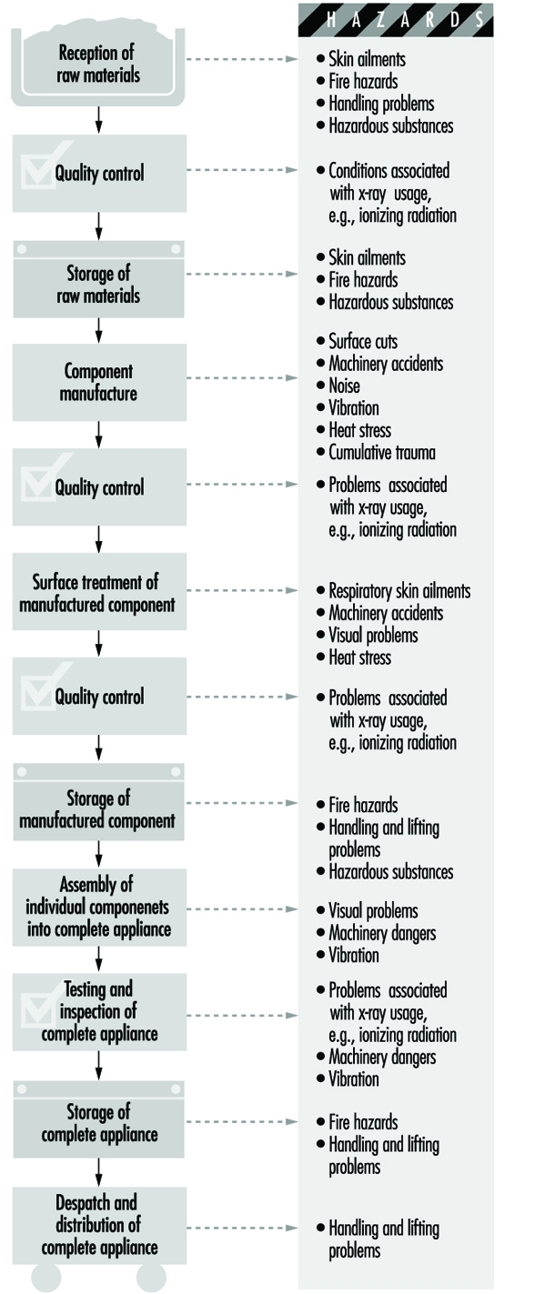
Health and Safety Issues
Fire and explosion
Many of the solvents, paints and insulating oils used in the industry are flammable substances. These materials should be stored in suitable cool, dry premises, preferably in a fireproof building separate from the production facility. Containers should be clearly labelled and different substances well separated or stored apart as required by their flashpoints and their class of risk. In the case of insulating materials and plastics, it is important to obtain information on the combustibility or fire characteristics of each new substance used. Powdered zirconium, which is now used in significant quantities in the industry, is also a fire hazard.
The quantities of flammable substances issued from storerooms should be kept to the minimum required for production. When flammable liquids are being decanted, charges of static electricity may form, and consequently all containers should be grounded. Fire-extinguishing appliances must be provided and the personnel of the storeplace instructed in their use.
Painting of components is usually carried out in specially built paint booths, which must have adequate exhaust and ventilation equipment that, when used with personal protective equipment (PPE), will create a safe working environment.
During welding, special fire precautions should be taken.
Accidents
Reception, storage and dispatch of raw materials, components and finished products can give rise to accidents involving trips and falls, falling objects, fork trucks and so forth. Manual materials handling can also create ergonomic problems which can be alleviated by automation whenever possible.
Since numerous different processes are employed in the industry, the accident hazards will vary from shop to shop in the plant. During component production there will be machine hazards in the use of machine tools, power presses, plastics injection-moulding machines and so on, and efficient machinery guarding is essential. During electroplating, precautions must be taken against splashes of corrosive chemicals. During component assembly, the constant movement of components from one process to another means that the danger of accidents due to in-plant transport and mechanical handling equipment is high.
Quality testing does not give rise to any special safety problems. However, performance testing requires special precautions since the tests are often carried out on semi-finished or uninsulated appliances. During electrical testing, all live components, conductors, terminals and measuring instruments should be protected to prevent accidental contact. The workplace should be screened off, entrance of unauthorized persons prohibited and warning notices posted. In electrical testing areas, the provision of emergency switches is particularly advisable, and the switches should be in a prominent position so that in an emergency all equipment can be immediately de-energized.
For testing appliances that emit x rays or contain radioactive substances, there are radiation protection regulations. A competent supervisor should be made responsible for observance of the regulations.
There are special risks in the use of compressed gases, welding equipment, lasers, impregnation plant, spray-painting equipment, annealing and tempering ovens and high-voltage electrical installations.
During all repair and maintenance activities, adequate lockout/tagout programmes are essential.
Health Hazards
Occupational diseases associated with the manufacture of domestic electrical equipment are relatively low in number and not normally considered to be severe. Such problems that do exist are typified by:
- the development of skin conditions due to the use of solvents, cutting oils, hardeners used with epoxy resin and polychlorinated biphenyls (PCBs)
- the onset of silicosis due to the inhalation of silica in sandblasting (although sand is being increasingly replaced by less toxic blasting agents such as corundum, steel grit or shot)
- health problems due to inhalation of solvent vapours in painting and degreasing, and lead poisoning from use of lead pigments, enamels, etc.
- varying levels of noise produced during the processes.
Wherever possible, highly toxic solvents and chlorinated compounds should be replaced by less dangerous substances; under no circumstances should benzene or carbon tetrachloride be employed as solvents. Lead poisoning may be overcome by substitution of safer materials or techniques and the strict application of safe working procedures, personal hygiene and medical supervision. Where there is a danger of exposure to hazardous concentrations of atmospheric contaminants, the workplace air should be regularly monitored, and appropriate measures such as the installation of an exhaust system taken where necessary. The noise hazard may be reduced by enclosure of noise sources, the use of sound-absorbent materials in workrooms or the use of personal hearing protection.
Safety engineers and industrial physicians should be called upon at the design and planning stage of new plants or operations, and the hazards of processes or machines should be eliminated before processes are started up. This should be followed up by regular inspection of machines, tools, plant, transport equipment, firefighting appliances, workshops and test areas and so on.
Worker participation in the safety effort is essential, and supervisors should ensure that personal protective equipment is available and worn where necessary. Particular attention should be paid to the safety training of new workers, since these account for a relatively high proportion of accidents.
Workers should receive a pre-placement medical examination and, where there is the possibility of hazardous exposure, periodic examination as necessary.
Many processes in the production of individual components will involve the rejection of waste material (e.g., “swarf” from sheet or bar metal), and the disposal of such materials must be in accordance with safety requirements. Furthermore, if such process waste cannot be returned to the producer or manufacturer for recycling, then its subsequent disposal must be by approved processes in order to avoid environmental pollution.
More...
Environmental and Public Health Issues
The main environmental problems associated with electrical appliance and equipment manufacture involve pollution and treatment of materials discarded during the manufacturing processes, together with the recycling, where possible, of the complete product when it has reached the end of its life.
Batteries
The exhaust of air contaminated with acid, alkali, lead, cadmium and other potentially harmful materials into the atmosphere and the pollution of water from the manufacturing of batteries should be prevented as far as possible, and where this is not possible it should be monitored to ensure compliance with relevant legislation.
The use of batteries can generate public health concerns. Leaking lead-acid or alkaline batteries can result in burns from the electrolyte. Recharging large lead-acid batteries can produce hydrogen gas, a fire and explosion hazard in enclosed areas. Release of thionyl chloride or sulphur dioxide from large lithium batteries can involve exposure to sulphur dioxide, hydrochloric acid mist, burning lithium and so on, and has caused at least one fatality (Ducatman, Ducatman and Barnes 1988). This could also be a hazard during manufacture of these batteries.
Battery manufacturers have become aware of increasing environmental concern from the disposal of batteries containing toxic heavy metals by putting them in landfills or incinerating them with other garbage. Leakage of toxic metals from waste dumps or alternatively escaping from the chimneys of waste incinerators can result in water and air contamination. The manufacturers therefore recognized the need to reduce the mercury content of batteries, in particular, within the limits allowable by modern technology. The campaign for mercury elimination commenced in advance of the legislation introduced in the European Union, the EC Battery Directive.
Recycling is another way to deal with environmental pollution. Nickel-cadmium batteries can be recycled relatively easily. The recovery of cadmium is very efficient and it is re-used in the construction of nickel-cadmium batteries. The nickel will subsequently be used in the steel industry. The initial economics suggested that the recycling of nickel-cadmium batteries was not cost effective, but advances in technology are expected to improve the situation. Mercuric oxide cells, which are covered by the EC Battery Directive, have been used primarily in hearing aids, and are being replaced typically with lithium or zinc-air batteries. Silver oxide cells are recycled, especially by the jewellery industry, due to the value of the silver content.
When recycling harmful materials, care has to be taken similar to that exercised during the manufacturing processes. During the recycling of silver batteries, for example, workers may be exposed to mercury vapour and silver oxide.
The repair and recycling of lead-acid batteries can result not only in lead poisoning among the workers, and sometimes their families, but also in extensive lead contamination of the environment (Matte et al. 1989). In many countries, particularly in the Caribbean and Latin America, lead car battery plates are burned to produce lead oxide for pottery glazes.
Electric Cable Manufacture
Electric cable manufacture has three major sources of pollution: solvent vapours, potential release of toluene di-isocyanate from enamelled wire manufacture and environmental emissions during the manufacture of materials used in cables. All of these require appropriate environmental controls.
Electric Lamp and Tube Manufacture
The major environmental concerns here are the waste disposal and/or recycling of mercury-containing lamps and the disposal of PCBs from the ballasts of fluorescent lamps. Glass manufacturing can also be a significant source of emission of nitrogen oxides into the atmosphere.
Domestic Electric Appliances
Since the electric appliance industry is to a large extent an assembly industry, environmental issues are minimal, with the major exception being paints and solvents used as surface coatings. Standard pollution control measures should be instituted in accordance with environmental regulations.
The recycling of electrical appliances involves separation of the recovered equipment into different materials such as copper and mild steel which can be reused, which is discussed elsewhere in this Encyclopaedia.
General Profile
The metal smelting and refining industry processes metal ores and scrap metal to obtain pure metals. The metal working industries process metals in order to manufacture machine components, machinery, instruments and tools which are needed by other industries as well as by the other different sectors of the economy. Various types of metals and alloys are used as starting materials, including rolled stock (bars, strips, light sections, sheets or tubes) and drawn stock (bars, light sections, tubes or wire). Basic metal processing techniques include:
- smelting and refining of metal ores and scrap
- casting molten metals into a given shape (foundry)
- hammering or pressing metals into the shape of a die (hot or cold forging)
- welding and cutting sheet metal
- sintering (compressing and heating materials in powder form, including one or more metals)
- shaping metals on a lathe.
A wide variety of techniques are used to finish metals, including grinding and polishing, abrasive blasting and many surface finishing and coating techniques (electroplating, galvanizing, heat treatment, anodizing, powder coating and so forth).
Foundries
Founding, or metal casting, involves the pouring of molten metal into the hollow inside of a heat-resistant mould which is the outside or negative shape of the pattern of the desired metal object. The mould may contain a core to determine the dimensions of any internal cavity in the final casting. Foundry work comprises:
- making a pattern of the desired article
- making the mould and cores and assembling the mould
- melting and refining the metal
- pouring the metal into the mould
- cooling the metal casting
- removing the mould and core from the metal casting
- removing extra metal from the finished casting.
The basic principles of foundry technology have changed little in thousands of years. However, processes have become more mechanized and automatic. Wooden patterns have been replaced by metal and plastic, new substances have been developed for producing cores and moulds, and a wide range of alloys are used. The most prominent foundry process is sand moulding of iron.
Iron, steel, brass and bronze are traditional cast metals. The largest sector of the foundry industry produces grey and ductile iron castings. Gray iron foundries use iron or pig iron (new ingots) to make standard iron castings. Ductile iron foundries add magnesium, cerium or other additives (often called ladle additives) to the ladles of molten metal before pouring to make nodular or malleable iron castings. The different additives have little impact on workplace exposures. Steel and malleable iron make up the balance of the ferrous foundry industrial sector. The major customers of the largest ferrous foundries are the auto, construction and agricultural implement industries. Iron foundry employment has decreased as engine blocks become smaller and can be poured in a single mould, and as aluminium is substituted for cast iron. Non-ferrous foundries, especially aluminium foundry and die-cast operations, have heavy employment. Brass foundries, both free standing and those producing for the plumbing equipment industry, are a shrinking sector which, however, remains important from an occupational health perspective. In recent years, titanium, chromium, nickel and magnesium, and even more toxic metals such as beryllium, cadmium and thorium, are used in foundry products.
Although the metal founding industry may be assumed to start by remelting solid material in the form of metal ingots or pigs, the iron and steel industry in the large units may be so integrated that the division is less obvious. For instance, the merchant blast furnace may turn all its output into pig iron, but in an integrated plant some iron may be used to produce castings, thus taking part in the foundry process, and the blast furnace iron may be taken molten to be turned into steel, where the same thing can occur. There is in fact a separate section of the steel trade known for this reason as ingot moulding. In the normal iron foundry, the remelting of pig iron is also a refining process. In the non-ferrous foundries the process of melting may require the addition of metals and other substances, and thus constitutes an alloying process.
Moulds made from silica sand bound with clay predominate in the iron foundry sector. Cores traditionally produced by baking silica sand bound with vegetable oils or natural sugars have been substantially replaced. Modern founding technology has developed new techniques to produce moulds and cores.
In general, the health and safety hazards of foundries can be classified by type of metal cast, moulding process, size of casting and degree of mechanization.
Process Overview
On the basis of the designer’s drawings, a pattern conforming to the external shape of the finished metal casting is constructed. In the same way, a corebox is made that will produce suitable cores to dictate the internal configuration of the final article. Sand casting is the most widely used method, but other techniques are available. These include: permanent mould casting, using moulds of iron or steel; die casting, in which the molten metal, often a light alloy, is forced into a metal mould under pressures of 70 to 7,000 kgf/cm2; and investment casting, where a wax pattern is made of each casting to be produced and is covered with refractory which will form the mould into which the metal is poured. The “lost foam” process uses polystyrene foam patterns in sand to make aluminium castings.
Metals or alloys are melted and prepared in a furnace which may be of the cupola, rotary, reverberatory, crucible, electric arc, channel or coreless induction type (see table 1). Relevant metallurgical or chemical analyses are performed. Molten metal is poured into the assembled mould either via a ladle or directly from the furnace. When the metal has cooled, the mould and core material are removed (shakeout, stripping or knockout) and the casting is cleaned and dressed (despruing, shot-blasting or hydro-blasting and other abrasive techniques). Certain castings may require welding, heat treatment or painting before the finished article will meet the specifications of the buyer.
Table 1. Types of foundry furnaces
|
Furnace |
Description |
|
Cupola furnace |
A cupola furnace is a tall, vertical furnace, open at the top with hinged doors at the bottom. It is charged from the top with alternate layers of coke, limestone and metal; the molten metal is removed at the bottom. Special hazards include carbon monoxide and heat. |
|
Electric arc furnace |
The furnace is charged with ingots, scrap, alloy metals and fluxing agents. An arc is produced between three electrodes and the metal charge, melting the metal. A slag with fluxes covers the surface of the molten metal to prevent oxidation, to refine the metal and protect the furnace roof from excessive heat. When ready, the electrodes are raised and the furnace tilted to pour the molten metal into the receiving ladle. Special hazards include metal fumes and noise. |
|
Induction furnace |
An induction furnace melts the metal by passing a high electric current through copper coils on the outside of the furnace, inducing an electric current in the outer edge of the metal charge that heats the metal because of the high electrical resistance of the metal charge. Melting progresses from the outside of the charge to the inside. Special hazards include metal fumes. |
|
Crucible furnace |
The crucible or container holding the metal charge is heated by a gas or oil burner. When ready, the crucible is lifted out of the furnace and tilted for pouring into moulds. Special hazards include carbon monoxide, metal fumes, noise and heat. |
|
Rotary furnace |
A long, inclined rotating cylindrical furnace that is charged from the top and fired from the lower end. |
|
Channel furnace |
A type of induction furnace. |
|
Reverberatory furnace |
This horizontal furnace consists of a fireplace at one end, separated from the metal charge by a low partition wall called the fire-bridge, and a stack or chimney at the other end. The metal is kept from contact with the solid fuel. Both the fireplace and metal charge are covered by an arched roof. The flame in its path from the fireplace to the stack is reflected downwards or reverberated on the metal beneath, melting it. |
Hazards such as the danger arising from the presence of hot metal are common to most foundries, irrespective of the particular casting process employed. Hazards may also be specific to a particular foundry process. For example, the use of magnesium presents flare risks not encountered in other metal founding industries. This article emphasizes iron foundries, which contain most of the typical foundry hazards.
The mechanized or production foundry employs the same basic methods as the conventional iron foundry. When moulding is done, for example, by machine and castings are cleaned by shot blasting or hydroblasting, the machine usually has built-in dust control devices, and the dust hazard is reduced. However, sand is frequently moved from place to place on an open-belt conveyor, and transfer points and sand spillage may be sources of considerable quantities of airborne dust; in view of the high production rates, the airborne dust burden may be even higher than in the conventional foundry. A review of air sampling data in the middle 1970s showed higher dust levels in large American production foundries than in small foundries sampled during the same period. Installation of exhaust hoods over transfer points on belt conveyors, combined with scrupulous housekeeping, should be normal practice. Conveying by pneumatic systems is sometimes economically possible and results in a virtually dust-free conveying system.
Iron Foundries
For simplicity, an iron foundry can be presumed to comprise the following six sections:
- metal melting and pouring
- pattern-making
- moulding
- coremaking
- shakeout/knockout
- casting cleaning.
In many foundries, almost any of these processes may be carried out simultaneously or consecutively in the same workshop area.
In a typical production foundry, iron moves from melting to pouring, cooling, shakeout, cleaning and shipping as a finished casting. Sand is cycled from sand mix, moulding, shakeout and back to sand mixing. Sand is added to the system from core making, which starts with new sand.
Melting and pouring
The iron founding industry relies heavily on the cupola furnace for metal melting and refining. The cupola is a tall, vertical furnace, open at the top with hinged doors at the bottom, lined with refractory and charged with coke, scrap iron and limestone. Air is blown through the charge from openings (tuyers) at the bottom; combustion of coke heats, melts and purifies the iron. Charge materials are fed into the top of the cupola by crane during operation and must be stored close at hand, usually in compounds or bins in the yard adjacent to the charging machinery. Tidiness and efficient supervision of the stacks of raw materials are essential to minimize the risk of injury from slippages of heavy objects. Cranes with large electromagnets or heavy weights are often used to reduce the scrap metal to manageable sizes for charging into the cupola and for filling the charging hoppers themselves. The crane cab should be well protected and the operators properly trained.
Employees handling raw materials should wear hand leathers and protective boots. Careless charging can overfill the hopper and can cause dangerous spillage. If the charging process is found to be too noisy, the noise of metal-on-metal impact can be reduced by fitting rubber noise-dampening liners to storage skips and bins. The charging platform is necessarily above ground level and can present a hazard unless it is level and has a non-slip surface and strong rails around it and any floor openings.
Cupolas generate large quantities of carbon monoxide, which may leak from the charging doors and be blown back by local eddy currents. Carbon monoxide is invisible, odourless and can quickly produce toxic ambient levels. Employees working on the charging platform or surrounding catwalks should be well trained in order to recognize the symptoms of carbon monoxide poisoning. Both continuous and spot monitoring of exposure levels are needed. Self-contained breathing apparatus and resuscitation equipment should be maintained in readiness, and operators should be instructed in their use. When emergency work is carried out, a confined-space entry system of contaminant monitoring should be developed and enforced. All work should be supervised.
Cupolas are usually sited in pairs or groups, so that while one is being repaired the others operate. The period of use must be based on experience with durability of refractories and on engineering recommendations. Procedures must be worked out in advance for tapping out iron and for shutting down when hot spots develop or if the water cooling system is disabled. Cupola repair necessarily involves the presence of employees inside the cupola shell itself to mend or renew refractory linings. These assignments should be considered confined-space entries and appropriate precautions taken. Precautions should also be taken to prevent the discharge of material through the charging doors at such times. To protect the workers from falling objects, they should wear safety helmets and, if working at a height, safety harnesses.
Workers tapping cupolas (transferring molten metal from the cupola well to a holding furnace or ladle) must observe rigorous personal protection measures. Goggles and protective clothing are essential. The eye protectors should resist both high velocity impact and molten metal. Extreme caution should be exercised in order to prevent remaining molten slag (the unwanted debris removed from the melt with the aid of the limestone additives) and metal from coming into contact with water, which will cause a steam explosion. Tappers and supervisors must ensure that any person not involved in the operation of the cupola remains outside the danger area, which is delineated by a radius of about 4 m from the cupola spout. Delineation of a non-authorized no-entry zone is a statutory requirement under the British Iron and Steel Foundries Regulations of 1953.
When the cupola run is at an end, the cupola bottom is dropped to remove the unwanted slag and other material still inside the shell before employees can carry out the routine refractory maintenance. Dropping the cupola bottom is a skilled and dangerous operation requiring trained supervision. A refractory floor or layer of dry sand on which to drop the debris is essential. If a problem occurs, such as jammed cupola bottom doors, great caution must be exercised to avoid risks of burns to workers from the hot metal and slag.
Visible white-hot metal is a danger to workers’ eyes due to the emission of infrared and ultraviolet radiation, extensive exposure to which can cause cataracts.
The ladle must be dried before filling with molten metal, to prevent steam explosions; a satisfactory period of flame heating must be established.
Employees in metal and pouring sections of the foundry should be provided with hard hats, tinted eye protection and face shields, aluminized clothing such as aprons, gaiters or spats (lower-leg and foot coverings) and boots. Use of protective equipment should be mandatory, and there should be adequate instruction in its use and maintenance. High standards of housekeeping and exclusion of water to the highest degree possible are needed in all areas where molten metal is being manipulated.
Where large ladles are slung from cranes or overhead conveyors, positive ladle-control devices should be employed to ensure that spillage of metal cannot occur if the operator releases his or her hold. Hooks holding molten metal ladles must be periodically tested for metal fatigue to prevent failure.
In production foundries, the assembled mould moves along a mechanical conveyor to a ventilated pouring station. Pouring may be from a manually controlled ladle with mechanical assist, an indexing ladle controlled from a cab, or it can be automatic. Typically, the pouring station is provided with a compensating hood with a direct air supply. The poured mould proceeds along the conveyor through an exhausted cooling tunnel until shakeout. In smaller, job shop foundries, moulds may be poured on a foundry floor and allowed to burn off there. In this situation, the ladle should be equipped with a mobile exhaust hood.
Tapping and transport of molten iron and charging of electric furnaces creates exposure to iron oxide and other metal oxide fumes. Pouring into the mould ignites and pyrolyses organic materials, generating large amounts of carbon monoxide, smoke, carcinogenic polynuclear aromatic hydrocarbons (PAHs) and pyrolysis products from core materials which may be carcinogenic and also respiratory sensitizers. Moulds containing large polyurethane bound cold box cores release a dense, irritating smoke containing isocyanates and amines. The primary hazard control for mould burn off is a locally exhausted pouring station and cooling tunnel.
In foundries with roof fans for exhausting pouring operations, high metal fume concentrations may be found in the upper regions where crane cabs are located. If the cabs have an operator, the cabs should be enclosed and provided with filtered, conditioned air.
Pattern making
Pattern making is a highly skilled trade translating the two-dimensional design plans to a three-dimensional object. Traditional wooden patterns are made in standard workshops containing hand tools and electric cutting and planing equipment. Here, all reasonably practicable measures should be taken to reduce the noise to the greatest extent possible, and suitable ear protectors must be provided. It is important that the employees are aware of the advantages of using such protection.
Power-driven wood cutting and finishing machines are obvious sources of danger, and often suitable guards cannot be fitted without preventing the machine from functioning at all. Employees must be well versed in normal operating procedure and should also be instructed in the hazards inherent in the work.
Wood sawing can create dust exposure. Efficient ventilation systems should be fitted to eliminate wood dust from the pattern shop atmosphere. In certain industries using hard woods, nasal cancer has been observed. This has not been studied in the founding industry.
Casting in permanent metal moulds, as in die-casting, has been an important development in the foundry industry. In this case, pattern making is largely replaced by engineering methods and is really a die manufacture operation. Most of the pattern-making hazards and the risks from sand are eliminated, but are replaced by the risk inherent in the use of some sort of refractory material to coat the die or mould. In modern die-foundry work, increasing use is made of sand cores, in which case the dust hazards of the sand foundry are still present.
Moulding
The most common moulding process in the iron founding industry uses the traditional “green sand” mould made from silica sand, coal dust, clay and organic binders. Other methods of mould production are adapted from coremaking: thermosetting, cold self-setting and gas-hardened. These methods and their hazards will be discussed under coremaking. Permanent moulds or the lost foam process may also be used, especially in the aluminium foundry industry.
In production foundries, sand mix, moulding, mould assembly, pouring and shakeout are integrated and mechanized. Sand from shakeout is recycled back to the sand mix operation, where water and other additives are added and the sand is mixed in mullers to maintain the desired physical properties.
For ease of assembly, patterns (and their moulds) are made in two parts. In manual mould-making, the moulds are enclosed in metal or wooden frames called flasks. The bottom half of the pattern is placed in the bottom flask (the drag), and first fine sand and then heavy sand are poured around the pattern. The sand is compacted in the mould by a jolt-squeeze, sand slinger or pressure process. The top flask (the cope) is prepared similarly. Wooden spacers are placed in the cope to form the sprue and riser channels, which are the pathway for the molten metal to flow into the mould cavity. The patterns are removed, the core inserted, and then the two halves of the mould assembled and fastened together, ready for pouring. In production foundries, the cope and drag flasks are prepared on a mechanical conveyor, cores are placed in the drag flask, and the mould assembled by mechanical means.
Silica dust is a potential problem wherever sand is handled. Moulding sand is usually either damp or mixed with liquid resin, and is therefore less likely to be a significant source of respirable dust. A parting agent such as talc is sometimes added to promote the ready removal of the pattern from the mould. Respirable talc causes talcosis, a type of pneumoconiosis. Parting agents are more widespread where hand moulding is employed; in the larger, more automatic processes they are rarely seen. Chemicals are sometimes sprayed onto the mould surface, suspended or dissolved in isopropyl alcohol, which is then burned off to leave the compound, usually a type of graphite, coating the mould in order to achieve a casting with a finer surface finish. This involves an immediate fire risk, and all employees involved in applying these coatings should be provided with fire-retardant protective clothing and hand protection, as organic solvents can also cause dermatitis. Coatings should be applied in a ventilated booth to prevent the organic vapours from escaping into the workplace. Strict precautions should also be observed to ensure that the isopropyl alcohol is stored and used with safety. It should be transferred to a small vessel for immediate use, and the larger storage vessels should be kept well away from the burning-off process.
Manual mould making can involve the manipulation of large and cumbersome objects. The moulds themselves are heavy, as are the moulding boxes or flasks. They are often lifted, moved and stacked by hand. Back injuries are common, and power assists are needed so employees do not need to lift objects too heavy to be carried safely.
Standardized designs are available for enclosures of mixers, conveyors and pouring and shakeout stations with appropriate exhaust volumes and capture and transport velocities. Adherence to such designs and strict preventive maintenance of control systems will attain compliance with international recognized limits for dust exposure.
Coremaking
Cores inserted into the mould determine the internal configuration of a hollow casting, such as the water jacket of an engine block. The core must withstand the casting process but at the same time must not be so strong as to resist removal from the casting during the knocking-out stage.
Prior to the 1960s, core mixtures comprised sand and binders, such as linseed oil, molasses or dextrin (oil sand). The sand was packed in a core box with a cavity in the shape of the core, and then dried in an oven. Core ovens evolve harmful pyrolysis products and require a suitable, well maintained chimney system. Normally, convection currents within the oven will be sufficient to ensure satisfactory removal of fumes from the workplace, although they contribute enormously to air pollution After removal from the oven, the finished oil sand cores can still give rise to a small amount of smoke, but the hazard is minor; in some cases, however, small amounts of acrolein in the fumes may be a considerable nuisance. Cores may be treated with a “flare-off coating” to improve the surface finish of the casting, which calls for the same precautions as in the case of moulds.
Hot box or shell moulding and coremaking are thermosetting processes used in iron foundries. New sand may be mixed with resin at the foundry, or resin-coated sand may be shipped in bags for addition to the coremaking machine. Resin sand is injected into a metal pattern (the core box). The pattern is then heated—by direct natural gas fires in the hot box process or by other means for shell cores and moulding. Hot boxes typically use a furfuryl alcohol (furan), urea- or phenol-formaldehyde thermosetting resin. Shell moulding uses a urea- or phenol-formaldehyde resin. After a short curing time, the core hardens considerably and can be pushed clear of the pattern plate by ejector pins. Hot box and shell coremaking generate substantial exposure to formaldehyde, which is a probable carcinogen, and other contaminants, depending on the system. Control measures for formaldehyde include direct air supply at the operator station, local exhaust at the corebox, enclosure and local exhaust at the core storage station and low-formaldehyde-emission resins. Satisfactory control is difficult to achieve. Medical surveillance for respiratory conditions should be provided to coremaking workers. Phenol- or urea-formaldehyde resin contact with the skin or eyes must be prevented because the resins are irritants or sensitizers and can cause dermatitis. Copious washing with water will help to avoid the problem.
Cold-setting (no-bake) hardening systems presently in use include: acid-catalyzed urea- and phenol-formaldehyde resins with and without furfuryl alcohol; alkyd and phenolic isocyanates; Fascold; self-set silicates; Inoset; cement sand and fluid or castable sand. Cold-setting hardeners do not require external heating to set. The isocyanates employed in binders are normally based on methylene diphenyl isocyanate (MDI), which, if inhaled, can act as a respiratory irritant or sensitizer, causing asthma. Gloves and protective goggles are advisable when handling or using these compounds. The isocyanates themselves should be carefully stored in sealed containers in dry conditions at a temperature between 10 and 30°C. Empty storage vessels should be filled and soaked for 24 hours with a 5% sodium carbonate solution in order to neutralize any residual chemical left in the drum. Most general housekeeping principles should be strictly applied to resin moulding processes, but the greatest caution of all should be exercised when handling the catalysts used as setting agents. The catalysts for the phenol and oil isocyanate resins are usually aromatic amines based on pyridine compounds, which are liquids with a pungent smell. They can cause severe skin irritation and renal and hepatic damage and can also affect the central nervous system. These compounds are supplied either as separate additives (three-part binder) or are ready mixed with the oil materials, and LEV should be provided at the mixing, moulding, casting and knockout stages. For certain other no-bake processes the catalysts used are phosphoric or various sulphonic acids, which are also toxic; accidents during transport or use should be adequately guarded against.
Gas-hardened coremaking comprises the carbon dioxide (CO2)-silicate and the Isocure (or “Ashland”) processes. Many variations of the CO2-silicate process have been developed since the 1950s. This process has generally been used for the production of medium to large moulds and cores. The core sand is a mixture of sodium silicate and silica sand, usually modified by adding such substances as molasses as breakdown agents. After the core box is filled, the core is cured by passing carbon dioxide through the core mixture. This forms sodium carbonate and silica gel, which acts as a binder.
Sodium silicate is an alkaline substance, and can be harmful if it comes into contact with the skin or eyes or is ingested. It is advisable to provide an emergency shower close to areas where large quantities of sodium silicate are handled and gloves should always be worn. A readily available eye-wash fountain should be located in any foundry area where sodium silicate is used. The CO2 can be supplied as a solid, liquid or gas. Where it is supplied in cylinders or pressure tanks, a great many housekeeping precautions should be taken, such as cylinder storage, valve maintenance, handling and so on. There is also the risk from the gas itself, since it can lower the oxygen concentration in the air in enclosed spaces.
The Isocure process is used for cores and moulds. This is a gas-setting system in which a resin, frequently phenol-formaldehyde, is mixed with a di-isocyanate (e.g., MDI) and sand. This is injected into the core box and then gassed with an amine, usually either triethylamine or dimethylethylamine, to cause the crosslinking, setting reaction. The amines, often sold in drums, are highly volatile liquids with a strong smell of ammonia. There is a very real risk of fire or explosion, and extreme care should be taken, especially where the material is stored in bulk. The characteristic effect of these amines is to cause halo vision and corneal swelling, although they also affect the central nervous system, where they can cause convulsions, paralysis and, occasionally, death. Should some of the amine come into contact with the eyes or skin, first-aid measures should include washing with copious quantities of water for at least 15 minutes and immediate medical attention. In the Isocure process, the amine is applied as a vapour in a nitrogen carrier, with excess amine scrubbed through an acid tower. Leakage from the corebox is the principle cause of high exposure, although offgassing of amine from manufactured cores is also significant. Great care should be taken at all times when handling this material, and suitable exhaust ventilation equipment should be installed to remove vapours from the working areas.
Shakeout, casting extraction and core knockout
After the molten metal has cooled, the rough casting must be removed from the mould. This is a noisy process, typically exposing operators well above 90 dBA over an 8 hour working day. Hearing protectors should be provided if it is not practicable to reduce the noise output. The main bulk of the mould is separated from the casting usually by jarring impact. Frequently the moulding box, mould and casting are dropped onto a vibrating grid to dislodge the sand (shakeout). The sand then drops through the grid into a hopper or onto a conveyor where it can be subjected to magnetic separators and recycled for milling, treatment and re-use, or merely dumped. Sometimes hydroblasting can be used instead of a grid, creating less dust. The core is removed here, also sometimes using high-pressure water streams.
The casting is then removed and transferred to the next stage of the knockout operation. Often small castings can be removed from the flask by a “punch-out” process before shakeout, which produces less dust. The sand gives rise to hazardous silica dust levels because it has been in contact with molten metal and is therefore very dry. The metal and sand remain very hot. Eye protection is needed. Walking and working surfaces must be kept free of scrap, which is a tripping hazard, and of dust, which can be resuspended to pose an inhalation hazard.
Relatively few studies have been carried out to determine what effect, if any, the new core binders have on the health of the de-coring operator in particular. The furanes, furfuryl alcohol and phosphoric acid, urea- and phenol-formaldehyde resins, sodium silicate and carbon dioxide, no-bakes, modified linseed oil and MDI, all undergo some type of thermal decomposition when exposed to the temperatures of the molten metals.
No studies have yet been conducted on the effect of the resin-coated silica particle on the development of pneumoconiosis. It is not known whether these coatings will have an inhibiting or accelerating effect on lung-tissue lesions. It is feared that the reaction products of phosphoric acid may liberate phosphine. Animal experiments and some selected studies have shown that the effect of the silica dust on lung tissue is greatly accelerated when silica has been treated with a mineral acid. Urea- and phenol-formaldehyde resins can release free phenols, aldehydes and carbon monoxide. The sugars added to increase collapsibility produce significant amounts of carbon monoxide. No-bakes will release isocyanates (e.g., MDI) and carbon monoxide.
Fettling (cleaning)
Casting cleaning, or fettling, is carried out following shakeout and core knockout. The various processes involved are variously designated in different places but can be broadly classified as follows:
- Dressing covers stripping, roughing or mucking-off, removal of adherent moulding sand, core sand, runners, risers, flash and other readily disposable matter with hand tools or portable pneumatic tools.
- Fettling covers removal of burnt-on moulding sand, rough edges, surplus metal, such as blisters, stumps of gates, scabs or other unwanted blemishes, and the hand cleaning of the casting using hand chisels, pneumatic tools and wire brushes. Welding techniques, such as oxyacetylene-flame cutting, electric arc, arc-air, powder washing and the plasma torch, may be employed for burning off headers, for casting repair and for cutting and washing.
Sprue removal is the first dressing operation. As much as half of the metal cast in the mould is not part of the final casting. The mould must include reservoirs, cavities, feeders and sprue in order that it be filled with metal to complete the cast object. The sprue usually can be removed during the knockout stage, but sometimes this must be carried out as a separate stage of the fettling or dressing operation. Sprue removal is done by hand, usually by knocking the casting with a hammer. To reduce noise, the metal hammers can be replaced by rubber-covered ones and the conveyors lined with the same noise-damping rubber. Hot metal fragments are thrown off and pose an eye hazard. Eye protection must be used. Detached sprues should normally be returned to the charging region of the melting plant and should not be permitted to accumulate at the despruing section of the foundry. After despruing (but sometimes before) most castings are shot blasted or tumbled to remove mould materials and perhaps to improve the surface finish. Tumbling barrels generate high noise levels. Enclosures may be necessary, which can also require LEV.
Dressing methods in steel, iron and non-ferrous foundries are very similar, but special difficulties exist in the dressing and fettling of steel castings owing to greater amounts of burnt-on fused sand compared to iron and non-ferrous castings. Fused sand on large steel castings may contain cristobalite, which is more toxic than the quartz found in virgin sand.
Airless shot blasting or tumbling of castings before chipping and grinding is needed to prevent overexposure to silica dust. The casting must be free of visible dust, although a silica hazard may still be generated by grinding if silica is burnt into the apparently clean metal surface of the casting. The shot is centrifugally propelled at the casting, and no operator is required inside the unit. The blast cabinet must be exhausted so no visible dust escapes. Only when there is a breakdown or deterioration of the shot-blast cabinet and/or the fan and collector is there a dust problem.
Water or water and sand or pressure shot blasting may be used to remove adherent sand by subjecting the casting to a high-pressure stream of either water or iron or steel shot. Sand blasting has been banned in several countries (e.g., the United Kingdom) because of the silicosis risk as the sand particles become finer and finer and the respirable fraction thus continually increases. The water or shot is discharged through a gun and can clearly present a risk to personnel if not handled correctly. Blasting should always be carried out in an isolated, enclosed space. All blasting enclosures should be inspected at regular intervals to ensure that the dust extraction system is functioning and that there are no leaks through which shot or water could escape into the foundry. Blasters’ helmets should be approved and carefully maintained. It is advisable to post a notice on the door to the booth, warning employees that blasting is under way and that unauthorized entry is prohibited. In certain circumstances delay bolts linked to the blast drive motor can be fitted to the doors, making it impossible to open the doors until blasting has ceased.
A variety of grinding tools are used to smooth the rough casting. Abrasive wheels may be mounted on floor-standing or pedestal machines or in portable or swing-frame grinders. Pedestal grinders are used for smaller castings that can be easily handled; portable grinders, surface disc wheels, cup wheels and cone wheels are used for a number of purposes, including smoothing of internal surfaces of castings; swing-frame grinders are used primarily on large castings that require a great deal of metal removal.
Other Foundries
Steel founding
Production in the steel foundry (as distinct from a basic steel mill) is similar to that in the iron foundry; however, the metal temperatures are much higher. This means that eye protection with coloured lenses is essential and that the silica in the mould is converted by heat to tridymite or crystobalite, two forms of crystalline silica which are particularly dangerous to the lungs. Sand often becomes burnt on to the casting and has to be removed by mechanical means, which give rise to dangerous dust; consequently, effective dust exhaust systems and respiratory protection are essential.
Light-alloy founding
The light-alloy foundry uses mainly aluminium and magnesium alloys. These often contain small amounts of metals which may give off toxic fumes under certain circumstances. The fumes should be analysed to determine their constituents where the alloy might contain such components.
In aluminium and magnesium foundries, melting is commonly done in crucible furnaces. Exhaust vents around the top of the pot for removing fumes are advisable. In oil-fired furnaces, incomplete combustion due to faulty burners may result in products such as carbon monoxide being released into the air. Furnace fumes may contain complex hydrocarbons, some of which may be carcinogenic. During furnace and flue cleaning there is the hazard of exposure to vanadium pentoxide concentrated in furnace soot from oil deposits.
Fluorspar is commonly used as a flux in aluminium melting, and significant quantities of fluoride dust may be released to the environment. In certain cases barium chloride has been used as a flux for magnesium alloys; this is a significantly toxic substance and, consequently, considerable care is required in its use. Light alloys may occasionally be degassed by passing sulphur dioxide or chlorine (or proprietary compounds that decompose to produce chlorine) through the molten metal; exhaust ventilation and respiratory protective equipment are required for this operation. In order to reduce the cooling rate of the hot metal in the mould, a mixture of substances (usually aluminium and iron oxide) which react highly exothermically is placed on the mould riser. This “thermite” mixture gives off dense fumes which have been found to be innocuous in practice. When the fumes are brown in colour, alarm may be caused due to suspicion of the presence of nitrogen oxides; however, this suspicion is unfounded. The finely divided aluminium produced during the dressing of aluminium and magnesium castings constitutes a severe fire hazard, and wet methods should be used for dust collection.
Magnesium casting entails considerable potential fire and explosion hazard. Molten magnesium will ignite unless a protective barrier is maintained between it and the atmosphere; molten sulphur is widely employed for this purpose. Foundry workers applying the sulphur powder to the melting pot by hand may develop dermatitis and should be provided with gloves made of fireproof fabric. The sulphur in contact with the metal is constantly burning, so considerable quantities of sulphur dioxide are given off. Exhaust ventilation should be installed. Workers should be informed of the danger of a pot or ladle of molten magnesium catching fire, which may give rise to a dense cloud of finely divided magnesium oxide. Protective clothing of fireproof materials should be worn by all magnesium foundry workers. Clothing coated with magnesium dust should not be stored in lockers without humidity control, since spontaneous combustion may occur. The magnesium dust should be removed from the clothing.French chalk is used extensively in mould dressing in magnesium foundries; the dust should be controlled to prevent talcosis. Penetrating oils and dusting powders are employed in the inspection of light-alloy castings for the detection of cracks.
Dyes have been introduced to improve the effectiveness of these techniques. Certain red dyes have been found to be absorbed and excreted in sweat, thus causing soiling of personal clothing; although this condition is a nuisance, no effects on health have been observed.
Brass and bronze foundries
Toxic metal fumes and dust from typical alloys are a special hazard of brass and bronze foundries. Exposures to lead above safe limits in both melting, pouring and finishing operations are common, especially where alloys have a high lead composition. The lead hazard in furnace cleaning and dross disposal is particularly acute. Overexposure to lead is frequent in melting and pouring and can also occur in grinding. Zinc and copper fumes (the constituents of bronze) are the most common causes of metal fume fever, although the condition has also been observed in foundry workers using magnesium, aluminium, antimony and so on. Some high-duty alloys contain cadmium, which can cause chemical pneumonia from acute exposure and kidney damage and lung cancer from chronic exposure.
Permanent-mould process
Casting in permanent metal moulds, as in die-casting, has been an important development in the foundry. In this case, pattern making is largely replaced by engineering methods and is really a die-sinking operation. Most of the pattern making hazards are thereby removed and the risks from sand are also eliminated but are replaced by a degree of risk inherent in the use of some sort of refractory material to coat the die or mould. In modern die-foundry work, increasing use is made of sand cores, in which case the dust hazards of the sand foundry are still present.
Die casting
Aluminium is a common metal in die casting. Automotive hardware such as chrome trim is typically zinc die cast, followed by copper, nickel and chrome plating. The hazard of metal fume fever from zinc fumes should be constantly controlled, as must be chromic acid mist.
Pressure die-casting machines present all the hazards common to hydraulic power presses. In addition, the worker may be exposed to the mist of oils used as die lubricants and must be protected against the inhalation of these mists and the danger of oil-saturated clothing. The fire-resistant hydraulic fluids used in the presses may contain toxic organophosphorus compounds, and particular care should be taken during maintenance work on hydraulic systems.
Precision founding
Precision foundries rely on the investment or lost-wax casting process, in which patterns are made by injection moulding wax into a die; these patterns are coated with a fine refractory powder which serves as a mould-facing material, and the wax is then melted out prior to casting or by the introduction of the casting metal itself.
Wax removal presents a definite fire hazard, and decomposition of the wax produces acrolein and other hazardous decomposition products. Wax-burnout kilns must be adequately ventilated. Trichloroethylene has been used to remove the last traces of wax; this solvent may collect in pockets in the mould or be absorbed by the refractory material and vaporize or decompose during pouring. The inclusion of asbestos investment casting refractory materials should be eliminated due to the hazards of asbestos.
Health Problems and Disease Patterns
Foundries stand out among industrial processes because of a higher fatality rate arising from molten metal spills and explosions, cupola maintenance including bottom drop and carbon monoxide hazards during relining. Foundries report a higher incidence of foreign body, contusion and burn injuries and a lower proportion of musculoskeletal injuries than other facilities. They also have the highest noise exposure levels.
A study of several dozen fatal injuries in foundries revealed the following causes: crushing between mould conveyor cars and building structures during maintenance and trouble-shooting, crushing while cleaning mullers which were remotely activated, molten metal burns after crane failure, mould cracking, overflowing transfer ladle, steam eruption in undried ladle, falls from cranes and work platforms, electrocution from welding equipment, crushing from material-handling vehicles, burns from cupola bottom drop, high-oxygen atmosphere during cupola repair and carbon monoxide overexposure during cupola repair.
Abrasive wheels
The bursting or breaking of abrasive wheels may cause fatal or very serious injuries: gaps between the wheel and the rest at pedestal grinders may catch and crush the hand or forearm. Unprotected eyes are at risk at all stages. Slips and falls, especially when carrying heavy loads, may be caused by badly maintained or obstructed floors. Injuries to the feet may be caused by falling objects or dropped loads. Sprains and strains may result from overexertion in lifting and carrying. Badly maintained hoisting appliances may fail and cause materials to fall on workers. Electric shock may result from badly maintained or unearthed (ungrounded) electrical equipment, especially portable tools.
All dangerous parts of machinery, especially abrasive wheels, should have adequate guarding, with automatic lockout if the guard is removed during processing. Dangerous gaps between the wheel and the rest at pedestal grinders should be eliminated, and close attention should be paid to all precautions in the care and maintenance of abrasive wheels and in regulation of their speed (particular care is required with portable wheels). Strict maintenance of all electrical equipment and proper grounding arrangements should be enforced. Workers should be instructed in correct lifting and carrying techniques and should know how to attach loads to crane hooks and other hoisting appliances. Suitable PPE, such as eye and face shields and foot and leg protection, should also be provided. Provision should be made for prompt first aid, even for minor injuries, and for competent medical care when needed.
Dust
Dust diseases are prominent among foundry workers. Silica exposures are often close to or exceed prescribed exposure limits, even in well-controlled cleaning operations in modern production foundries and where castings are free of visible dust. Exposures many times above the limit occur where castings are dusty or cabinets leak. Overexposures are likely where visible dust escapes venting in shakeout, sand preparation or refractory repair.
Silicosis is the predominant health hazard in the steel fettling shop; a mixed pneumoconiosis is more prevalent in iron fettling (Landrigan et al. 1986). In the foundry, the prevalence increases with length of exposure and higher dust levels. There is some evidence that conditions in steel foundries are more likely to cause silicosis than those in iron foundries because of the higher levels of free silica present. Attempts to set an exposure level at which silicosis will not occur have been inconclusive; the threshold is probably less than 100 micrograms/m3 and perhaps as low as half that amount.
In most countries, the occurrence of new cases of silicosis is declining, in part because of changes in technology, a move away from silica sand in foundries and a shift away from silica brick and towards basic furnace linings in steel melting. A major reason is the fact that automation has resulted in the employment of fewer workers in steel production and foundries. Exposure to respirable silica dust remains stubbornly high in many foundries, however, and in countries where processes are labour intensive, silicosis remains a major problem.
Silico-tuberculosis has long been reported in foundry workers. Where the prevalence of silicosis has declined, there has been a parallel falling off in reported cases of tuberculosis, although that disease has not been completely eradicated. In countries where dust levels have remained high, dusty processes are labour intensive and the prevalence of tuberculosis in the general population is elevated, tuberculosis remains an important cause of death amongst foundry workers.
Many workers suffering from pneumoconiosis also have chronic bronchitis, often associated with emphysema; it has long been thought by many investigators that, in some cases at least, occupational exposures may have played a part. Cancer of the lung, lobar pneumonia, bronchopneumonia and coronary thrombosis have also been reported to be associated with pneumoconiosis in foundry workers.
A recent review of mortality studies of foundry workers, including the American auto industry, showed increased deaths from lung cancer in 14 of 15 studies. Because high lung cancer rates are found among cleaning room workers where the primary hazard is silica, it is likely that mixed exposures are also found.
Studies of the carcinogens in the foundry environment have concentrated on polycyclic aromatic hydrocarbons formed in the thermal breakdown of sand additives and binders. It has been suggested that metals such as chromium and nickel, and dusts such as silica and asbestos, may also be responsible for some of the excess mortality. Differences in moulding and core-making chemistry, sand type and the composition of iron and steel alloys may be responsible for different levels of risk in different foundries (IARC 1984).
Increased mortality from non-malignant respiratory disease was found in 8 of 11 studies. Silicosis deaths were recorded as well. Clinical studies found x-ray changes characteristic of pneumoconiosis, lung function deficits characteristic of obstruction, and increased respiratory symptoms among workers in modern “clean” production foundries. These resulted from exposures after the l960s and strongly suggest that the health risks prevalent in the older foundries have not yet been eliminated.
Prevention of lung disorders is essentially a matter of dust and fume control; the generally applicable solution is providing good general ventilation coupled with efficient LEV. Low-volume, high-velocity systems are most suitable for some operations, particularly portable grinding wheels and pneumatic tools.
Hand or pneumatic chisels used to remove burnt-on sand produce much finely divided dust. Brushing off excess materials with revolving wire brushes or hand brushes also produces much dust; LEV is required.
Dust control measures are readily adaptable to floor-standing and swing-frame grinders. Portable grinding on small castings can be carried out on exhaust-ventilated benches, or ventilation may be applied to the tools themselves. Brushing can also be carried out on a ventilated bench. Dust control on large castings presents a problem, but considerable progress has been made with low-volume, high-velocity ventilation systems. Instruction and training in their use is needed to overcome the objections of workers who find these systems cumbersome and complain that their view of the working area is impaired.
Dressing and fettling of very large castings where local ventilation is impracticable should be done in a separate, isolated area and at a time when few other workers are present. Suitable PPE that is regularly cleaned and repaired, should be provided for each worker, along with instruction in its proper use.
Since the 1950s, a variety of synthetic resin systems have been introduced into foundries to bind sand in cores and moulds. These generally comprise a base material and a catalyst or hardener which starts the polymerization. Many of these reactive chemicals are sensitizers (e.g., isocyanates, furfuryl alcohol, amines and formaldehyde) and have now been implicated in cases of occupational asthma among foundry workers. In one study, 12 out of 78 foundry workers exposed to Pepset (cold-box) resins had asthmatic symptoms, and of these, six had a marked decline in airflow rates in a challenge test using methyl di-isocyanate (Johnson et al. 1985).
Welding
Welding in fettling shops exposes workers to metal fumes with the consequent hazard of toxicity and metal fever, depending on the composition of the metals involved. Welding on cast iron requires a nickel rod and creates exposure to nickel fumes. The plasma torch produces a considerable amount of metal fumes, ozone, nitrogen oxide and ultraviolet radiation, and generates high levels of noise.
An exhaust-ventilated bench can be provided for welding small castings. Controlling exposures during welding or burning operations on large castings is difficult. A successful approach involves creating a central station for these operations and providing LEV through a flexible duct positioned at the point of welding. This requires training the worker to move the duct from one location to another. Good general ventilation and, when necessary, the use of PPE will aid in reducing the overall dust and fume exposures.
Noise and vibration
The highest levels of noise in the foundry are usually found in knockout and cleaning operations; they are higher in mechanized than in manual foundries. The ventilation system itself may generate exposures close to 90 dBA.
Noise levels in the fettling of steel castings may be in the range of 115 to 120 dBA, while those actually encountered in the fettling of cast iron are in the 105 to 115 dBA range. The British Steel Casting Research Association established that the sources of noise during fettling include:
- the fettling tool exhaust
- the impact of the hammer or wheel on the casting
- resonance of the casting and vibration against its support
- transmission of vibration from the casting support to surrounding structures
- reflection of direct noise by the hood controlling air flow through the ventilation system.
Noise control strategies vary with the size of the casting, the type of metal, the work area available, the use of portable tools and other related factors. Certain basic measures are available to reduce noise exposure of individuals and co-workers, including isolation in time and space, complete enclosures, partial sound-absorbing partitions, execution of work on sound-absorbing surfaces, baffles, panels and hoods made from sound-absorbing or other acoustical materials. The guidelines for safe daily exposure limits should be observed and, as a last resort, personal protective devices may be used.
A fettling bench developed by the British Steel Casting Research Association reduces the noise in chipping by about 4 to 5 dBA. This bench incorporates an exhaust system to remove dust. This improvement is encouraging and leads to hope that, with further development, even greater noise reductions will become possible.
Hand-arm vibration syndrome
Portable vibrating tools may cause Raynaud’s phenomenon (hand-arm vibration syndrome—HAVS). This is more prevalent in steel fettlers than in iron fettlers and more frequent among those using rotating tools. The critical vibratory rate for the onset of this phenomenon is between 2,000 and 3,000 revolutions per minute and in the range of 40 to 125 Hz.
HAVS is now thought to involve effects on a number of other tissues in the forearm apart from peripheral nerves and blood vessels. It is associated with carpal tunnel syndrome and degenerative changes in the joints. A recent study of steelworks chippers and grinders showed they were twice as likely to develop Dupuytren’s contracture than a comparison group (Thomas and Clarke 1992).
Vibration transmitted to the hands of the worker can be considerably reduced by: selection of tools designed to reduce the harmful ranges of frequency and amplitude; direction of the exhaust port away from the hand; use of multiple layers of gloves or an insulating glove; and shortening of exposure time by changes in work operations, tools and rest periods.
Eye problems
Some of the dusts and chemicals encountered in foundries (e.g., isocyanates, formaldehyde and tertiary amines, such as dimethlyethylamine, triethylamine and so on) are irritants and have been responsible for visual symptoms among exposed workers. These include itchy, watery eyes, hazy or blurred vision or so called “blue-grey vision”. On the basis of the occurrence of these effects, reducing time-weighted average exposures below 3 ppm has been recommended.
Other problems
Formaldehyde exposures at or above the US exposure limit are found in well-controlled hot-box core-making operations. Exposures many times above the limit may be found where hazard control is poor.
Asbestos has been used widely in the foundry industry and, until recently, it was often used in protective clothing for heat-exposed workers. Its effects have been found in x-ray surveys of foundry workers, both among production workers and maintenance workers who have been exposed to asbestos; a cross-sectional survey found the characteristic pleural involvement in 20 out of 900 steel workers (Kronenberg et al. 1991).
Periodic examinations
Preplacement and periodic medical examinations, including a survey of symptoms, chest x rays, pulmonary function tests and audiograms, should be provided for all foundry workers with appropriate follow-up if questionable or abnormal findings are detected. The compounding effects of tobacco smoke on the risk of respiratory problems among foundry workers mandate inclusion of advice on smoking cessation in a programme of health education and promotion.
Conclusion
Foundries have been an essential industrial operation for centuries. Despite continuing advances in technology, they present workers with a panoply of hazards to safety and health. Because hazards continue to exist even in the most modern plants with exemplary prevention and control programmes, protecting the health and well-being of workers remains an ongoing challenge to management and to the workers and their representatives. This remains difficult both in industry downturns (when concerns for worker health and safety tend to give way to economic stringencies) and in boom times (when the demand for increased output may lead to potentially dangerous short cuts in the processes). Education and training in hazard control, therefore, remain a constant necessity.
Forging and Stamping
Process Overview
Forming metal parts by application of high compressive and tensile forces is common throughout industrial manufacturing. In stamping operations, metal, most often in the form of sheets, strips or coils, is formed into specific shapes at ambient temperatures by shearing, pressing and stretching between dies, usually in a series of one or more discrete impact steps. Cold-rolled steel is the starting material in many stamping operations creating sheet metal parts in the automotive and appliance and other industries. Approximately 15% of workers in the automotive industry work in stamping operations or plants.
In forging, compressive force is applied to pre-formed blocks (blanks) of metal, usually heated to high temperatures, also in one or more discrete pressing steps. The shape of the final piece is determined by the shape of the cavities in the metal die or dies used. With open impression dies, as in drop hammer forging, the blank is compressed between one die attached to the bottom anvil and the vertical ram. With closed impression dies, as in press forging, the blank is compressed between the bottom die and an upper die attached to the ram.
Drop hammer forges use a steam or air cylinder to raise the hammer, which is then dropped by gravity or is driven by steam or air. The number and force of the hammer blows are manually controlled by the operator. The operator often holds the cold end of the stock while operating the drop hammer. Drop hammer forging once comprised about two-thirds of all forging done in the United States, but is less common today.
Press forges use a mechanical or hydraulic ram to shape the piece with a single, slow, controlled stroke (see figure 1). Press forging is usually controlled automatically. It can be done hot or at normal temperatures (cold-forging, extruding). A variation on normal forging is rolling, where continuous applications of force are used and the operator turns the part.
Figure 1. Press forging
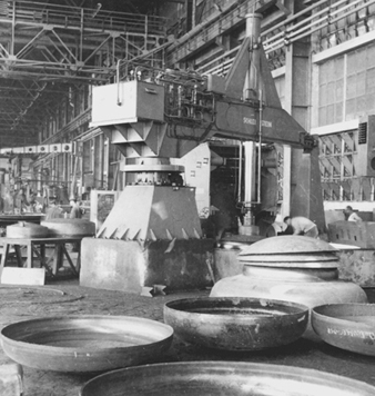
Die lubricants are sprayed or otherwise applied to die faces and blank surfaces before and between hammer or press strokes.
High-strength machine parts such as shafts, ring gears, bolts and vehicle suspension components are common steel forging products. High-strength aircraft components such as wing spars, turbine disks and landing gear are forged from aluminium, titanium or nickel and steel alloys. Approximately 3% of automotive workers are in forging operations or plants.
Working Conditions
Many hazards common in heavy industry are present in stamping and forging operations. These include repetitive strain injuries (RSIs) from repeated handling and processing of parts and operation of machine controls such as palm buttons. Heavy parts place workers at risk for back and shoulder problems as well as upper extremity musculoskeletal disorders. Press operators in automotive stamping plants have rates of RSIs that are comparable to those of assembly plant workers in high-risk jobs. High-impulse vibration and noise are present in most stamping and some forging (e.g., steam or air hammer) operations, causing hearing loss and possible cardiovascular illness; these are among the highest-noise industrial environments (over 100 dBA). As in other forms of automation-driven systems, worker energy loads can be high, depending on the parts handled and machine cycling rates.
Catastrophic injuries resulting from unanticipated machine movements are common in stamping and forging. These can be due to: (1) mechanical failure of machine control systems, such as clutch mechanisms in situations where workers are routinely expected to be within the machine operating envelope (an unacceptable process design); (2) deficiencies in machine design or performance that invite unprogrammed worker interventions such as moving jammed or misaligned parts; or (3) improper, high-risk maintenance procedures performed without adequate lockout of the entire machine network involved, including parts transfer automation and the functions of other connected machines. Most automated machine networks are not configured for quick, efficient and effective lockout or safe trouble-shooting.
Mists from machine lubricating oils generated during normal operation are another generic health hazard in stamping and forging press operations powered by compressed air, potentially putting workers at risk for respiratory, dermatological and digestive diseases.
Health and Safety Problems
Stamping
Stamping operations have high risk of severe laceration due to the required handling of parts with sharp edges. Possibly worse is the handling of the scrap resulting from cut-off perimeters and punched out sections of parts. Scrap is typically collected by gravity-fed chutes and conveyors. Clearing occasional jams is a high-risk activity.
Chemical hazards specific to stamping typically arise from two main sources: drawing compounds (i.e., die lubricants) in actual press operations and welding emissions from assembly of the stamped parts. Drawing compounds (DCs) are required for most stamping. The material is sprayed or rolled onto sheet metal and further mists are generated by the stamping event itself. Like other metalworking fluids, drawing compounds may be straight oils or oil emulsions (soluble oils). Components include petroleum oil fractions, special lubricity agents (e.g., animal and vegetable fatty acid derivatives, chlorinated oils and waxes), alkanolamines, petroleum sulphonates, borates, cellulose-derived thickeners, corrosion inhibitors and biocides. Air concentrations of mist in stamping operations may reach those of typical machining operations, although these levels tend to be lower on average (0.05 to 2.0 mg/m3). However, visible fog and accumulated oil film on building surfaces are often present, and skin contact may be higher due to extensive handling of parts. Exposures most likely to present hazards are chlorinated oils (possible cancer, liver disease, skin disorders), rosin or tall oil fatty acid derivatives (sensitizers), petroleum fractions (digestive cancers) and, possibly, formaldehyde (from biocides) and nitrosamines (from alkanolamines and sodium nitrite, either as DC ingredients or in surface coatings on incoming steel). Elevated digestive cancer has been observed in two automotive stamping plants. Microbiological blooms in systems that apply DCs by rolling it onto sheet metal from an open reservoir can pose risks to workers for respiratory and dermatological problems analogous to those in machining operations.
Welding of stamped parts is often performed in stamping plants, usually without intermediate washing. This produces emissions that include metal fumes and pyrolysis and combustion products from drawing compound and other surface residues. Typical (primarily resistance) welding operations in stamping plants generate total particulate air concentrations in the range 0.05 to 4.0 mg/m3. Metal content (as fumes and oxides) usually makes up less than half of that particulate matter, indicating that up to 2.0 mg/m3 is poorly characterized chemical debris. The result is haze visible in many stamping plant welding areas. The presence of chlorinated derivatives and other organic ingredients raises serious concerns over the composition of welding smoke in these settings and strongly argues for ventilation controls. Application of other materials prior to welding (such as primer, paint and epoxy-like adhesives), some of which are then welded over, adds further concern. Welding production repair activities, usually done manually, often pose higher exposures to these same air contaminants. Excess rates of lung cancer have been observed among welders in an automotive stamping plant.
Forging
Like stamping, forging operations can pose high laceration risks when workers handle forged parts or trim the flash or unwanted edges off parts. High impact forging can also eject fragments, scale or tools, causing injury. In some forging activities, the worker grasps the working piece with tongs during the pressing or impact steps, increasing the risk for musculoskeletal injuries. In forging, unlike stamping, furnaces for heating parts (for forging and annealing) as well as bins of hot forgings are usually nearby. These create potential for high heat stress conditions. Additional factors in heat stress are the worker’s metabolic load during manual handling of materials and, in some cases, heat from combustion products of oil-based die lubricants.
Die lubrication is required in most forging and has the added feature that the lubricant comes in contact with high-temperature parts. This causes immediate pyrolysis and aerosolization not only in the dies but also subsequently from smoking parts in cooling bins. Forging die lubricant ingredients can include graphite slurries, polymeric thickeners, sulphonate emulsifiers, petroleum fractions, sodium nitrate, sodium nitrite, sodium carbonate, sodium silicate, silicone oils and biocides. These are applied as sprays or, in some applications, by swab. Furnaces used for heating metal to be forged are usually fired by oil or gas, or they are induction furnaces. Emissions can result from fuel-fired furnaces with inadequate draft and from non-ventilated induction furnaces when incoming metal stock has surface contaminants, such as oil or corrosion inhibitors, or if, prior to forging, it was lubricated for shearing or sawing (as in the case of bar stock). In the US, total particulate air concentrations in forging operations typically range from 0.1 to 5.0 mg/m3 and vary widely within forging operations due to thermal convection currents. An elevated lung cancer rate was observed among forging and heat treatment workers from two ball-bearing manufacturing plants.
Health and Safety Practices
Few studies have evaluated actual health effects in workers with stamping or forging exposures. Comprehensive characterization of the toxicity potential of most routine operations, including identification and measurement of priority toxic agents, has not been done. Evaluating the long-term health effects of die lubrication technology developed in the 1960s and 1970s has only recently become feasible. As a result, regulation of these exposures defaults to generic dust or total particulate standards such as 5.0 mg/m3 in the US. While probably adequate in some circumstances, this standard is not demonstrably adequate for many stamping and forging applications.
Some reduction in die lubricant mist concentrations is possible with careful management of the application procedure in both stamping and forging. Roll application in stamping is preferred when feasible, and using minimal air pressure in sprays is beneficial. Possible elimination of priority hazardous ingredients should be investigated. Enclosures with negative pressure and mist collectors can be highly effective but may be incompatible with parts handling. Filtering air released from high-pressure air systems in presses would reduce press oil mist (and noise). Skin contact in stamping operations can be reduced with automation and good personal protective wear, providing protection against both laceration and liquid saturation. For stamping plant welding, washing parts prior to welding is highly desirable, and partial enclosures with LEV would reduce smoke levels substantially.
Controls to reduce heat stress in stamping and hot forging include minimizing the amount of manual material handling in high-heat areas, shielding of furnaces to reduce radiation of heat, minimizing the height of furnace doors and slots and using cooling fans. The location of cooling fans should be an integral part of the design of air movement to control mist exposures and heat stress; otherwise, cooling may be obtained only at the expense of higher exposures.
Mechanization of material handling, switching from hammer to press forging when possible and adjusting the work rate to ergonomically practical levels can reduce the number of musculoskeletal injuries.
Noise levels can be reduced through a combination of switching from hammer to press forges when possible, well-designed enclosures and quieting of furnace blowers, air clutches, air leads and parts handling. A hearing conservation programme should be instituted.
PPE needed includes head protection, foot protection, goggles, hearing protectors (around are as with excessive noise), heat- and oil-proof aprons and leggings (with heavy use of oil-based die lubricants) and infrared eye and face protection (around furnaces).
Environmental Health Hazards
The environmental hazards arising from stamping plants, relatively minor compared to those from some other types of plants, include disposal of waste drawing compound and washing solutions and the exhausting of welding smoke without adequate cleaning. Some forging plants historically have caused acute degradation of local air quality with forging smoke and scale dust. However, with appropriate air cleaning capacity, this need not occur. Disposition of stamping scrap and forging scale containing die lubricants is another potential issue.
" DISCLAIMER: The ILO does not take responsibility for content presented on this web portal that is presented in any language other than English, which is the language used for the initial production and peer-review of original content. Certain statistics have not been updated since the production of the 4th edition of the Encyclopaedia (1998)."